
Related Manuals for Lanner NCA-6250 Series


Summary of Contents for Lanner NCA-6250 Series
- Page 1 Network Appliance Platform Hardware Platforms for Network Computing NCA-6250 User Manual Version: 1.0 Date of Release:2024-11-12...
- Page 2 - assumed to be qualified in the servicing of computer equipment, such as professional system integrators, or service personnel and technicians. The latest version of this document can be found on Lanner’s official website, available either through the product page or through the Lanner Download Center page with a login account and password.
-
Page 3: Contact Information
221 新北市汐止區 service@ls-china.com.cn 大同路二段 173 號 7 樓 T: +886-2-8692-6060 F: +886-2-8692-6101 contact@lannerinc.com Canada Lanner Electronics Inc. Lanner Electronics Canada Ltd 47790 Westinghouse Drive 3160A Orlando Drive Fremont, CA 94539 Mississauga, ON T: +1-855-852-6637 L4V 1R5 Canada F: +1-510-979-0689 T: +1 877-813-2132 sales_us@lannerinc.com... -
Page 4: Federal Communication Commission Interference Statement
NCA-6250 User Manual Acknowledgment Intel® and Intel® Celeron® are trademarks of Intel Corporation or its subsidiaries in the U.S. and/or other countries. Microsoft Windows and MS-DOS are registered trademarks of Microsoft Corp. All other product names or trademarks are properties of their respective owners. Federal Communication Commission Interference Statement This equipment has been tested and found to comply with the limits for a Class A digital device, pursuant to Part 15 of FCC Rules. -
Page 5: Safety Guidelines
NCA-6250 User Manual Safety Guidelines Follow these guidelines to ensure general safety: Keep the chassis area clear and dust-free during and after installation. Do not wear loose clothing or jewelry that could get caught in the chassis. Fasten your tie or scarf and roll up your sleeves. -
Page 6: Sécurité De Fonctionnement
The installation of this product must be performed by trained specialists; otherwise, a non-specialist might create the risk of the system’s falling to the ground or other damages. Lanner Electronics Inc. shall not be held liable for any losses resulting from insufficient strength for supporting the system or use of inappropriate installation components. - Page 7 NCA-6250 User Manual Grounding Procedure for This Device Connect the grounding cable to the ground. The protection device for the DC power source must provide 40A current. This protection device must be connected to the power source before DC power. Procédure de mise à...
-
Page 8: Table Of Contents
NCA-6250 User Manual Table of Contents Chapter 1: Product Overview ............10 Package Content ......................... 10 Ordering Information ......................... 10 Optional Accessories ........................11 System Specifications ......................... 12 Front Panel ..........................13 Rear Panel ........................... 14 Chapter 2: Motherboard Information ..........15 Motherboard Layout ........................ - Page 9 NCA-6250 User Manual Chapter 4: Remote Server Management ........62 BMC Main Features ........................62 BMC Firmware Functional Description ..................63 IPMI Commands Support List ..................... 65 Using BMC Web UI ........................67 Chapter 5: BIOS Setup ..............72 Main Page ........................... 73 Advanced Page ...........................
-
Page 10: Chapter 1: Product Overview
NCA-6250 User Manual CHAPTER 1: PRODUCT OVERVIEW The NCA-6250 series unit is a high performance 2U Rack mount network security system utilizing the cutting-edge capabilities of the Intel® Birch stream platform with dual Sierra Forest SP (E-core) / Granite Rapids SP (P-cores) CPU. The system supports difference SKUs up to 8x NCS2 modules or 4x N2S module. -
Page 11: Optional Accessories
NCA-6250 User Manual Optional Accessories Model Description IAC-TPM04B TPM 2.0 Module M.2 NVMe Power Cable For Active Heatsink on PCIe Gen5 M.2 2280 Module VGA Cable VGA Cables Kit Riser Card Kit-1 Riser card kit for center 1x Double-deck FH3/4L PCIe bracket (under RC-62502 150W) for NVIDIA A10 GPU Module Riser Card Kit-2... -
Page 12: System Specifications
NCA-6250 User Manual System Specifications Form Factor 2U 19“ Rackmount 2x Intel® Xeon®6 Scalable Processors Birch Stream (Sierra Forest- Processor Options SP/Granite Rapids-SP/ Clearwater Forest-SP) CPU Socket 2x LGA4710 Platform Chipset ASPEED AST2600 BMC Chip Security Acceleration Intel® QuickAssist Technology BIOS AMI SPI Flash BIOS Technology... -
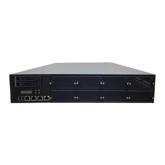
Page 13: Front Panel
NCA-6250 User Manual Front Panel SLOT5 SLOT6 SLOT7 SLOT8 SLOT1 SLOT2 SLOT3 SLOT4 F8 F9 Description HDD/SSD Bays 2x 2.5” U.2 SSD Trays (Default NVMe) (SATA Optional) VGA Port DB15 VGA Semi-Hole (Optional) 16x2 Character LCD, 4x Keypads Reset Button 1x Software Reset Button System Power LED Indicators... -
Page 14: Rear Panel
NCA-6250 User Manual Rear Panel Description 4x Cooling Smart Fans Power Switch 1x Power Button Ground Hole 1x Semi-Shearing Hole for Grounding screw ESD Jack 1x Semi-Shearing Hole for ESD screw Power Supply 2x 1+1 Redundant CRPS Power Supply... -
Page 15: Chapter 2: Motherboard Information
NCA-6250 User Manual CHAPTER 2: MOTHERBOARD INFORMATION Block Diagram The block diagram indicates how data flows among components on the motherboard. Please refer to the following figure for the motherboard layout design. - Page 16 NCA-6250 User Manual...
-
Page 17: Motherboard Layout
NCA-6250 User Manual Motherboard Layout The motherboard layout shows the connectors and jumpers on the board. Refer to the following picture as a reference of the pin assignments and the internal connectors. Name Name Name Name JPCIESL1~4 BAT1 JESPI80P1 JUPDATE1 JPCIESL5 JLCM1 JPLD1... -
Page 18: Internal Jumper & Connectors
Internal Jumper & Connectors Board to Board Connector 1. JPCIESL1~4: PCIe x8 Gen5 Connector, Connect to NIC Module (Lanner NCS2 Module) 2. JPCIESL5: Board to Board Slot, Connect to Rear Expansion for 1xPCIE*16 Card (RC-62502) 3. JPCIESL6: Board to Board slot, Connect to IO Card (IO-62501) 4. - Page 19 NCA-6250 User Manual 14. JSATAPW1~2, JNGFFPW1: SATA 4-Pin Power Connector Description +P12V +P5V Function Connector and Pin Header 15. JFAN1~4: Fan Connector Description +P12V +P12V RPM Sense RPM Sense 16. BAT1: Battery Connector Description +P3V3_BAT +P3V3_BAT 17. JLCM1: LCM Function (Signals share with JCOM1) Description +P5V 18.
- Page 20 NCA-6250 User Manual 19. CON3: CPU Console Description +P3V3_AUX 20. JBMC_UART1: BMC Console Description +P3V3_AUX 21. JRAID_CON1: VROC Key Connector Description PU_VROC_HW_KEY FM_VROC_HW_KEY 22. JIPMB1: VROC Key Connector Description SMB_IPMB_SDA SMB_IPMB_SCL +P5V_AUX 23. JVGA1: VGA Connector Description Description DAC_RO DAC_GO DAC_BO HSYNC_O VSYNC_O...
- Page 21 NCA-6250 User Manual 24. JPWR1: Power Button Cable Connector Description PWRBTN 25. JOPEN1: Case Open Cable Connector Description DE_PSU_BEEP_SW 26. JPSU_ALERT_BEEP1: Alert Cable Connector Description DE_PSU_BEEP_SW 27. BZ1: Buzzer Function 28. JSPI_TPM1: TPM Pin Header Description Description +PVCCFA_EHV_P1V8_AUX SPI_MISO SPI_CLK SPI_MOSI IRQ_TPM SPI_CS...
- Page 22 NCA-6250 User Manual 30. JUSB1: USB2 Pin Header Description Description +P5V USB20_N USB20_P 31. JESPI80P1: Debug Port Pin Header Description Description ESPI_CLK_HDR ESPI_IO1_HDR RST_ESPI_HDR ESPI_IO0_HDR ESPI_CS_HDR +P3V3 ESPI_IO3_HDR ESPI_IO2_HDR +P3V3_AUX 32. JPLD1: FPGA Pin Header, For FPGA Programming Description Description ESPI_CLK_HDR ESPI_IO1_HDR RST_ESPI_HDR...
- Page 23 NCA-6250 User Manual SPI_CPU0_IO1 SPI_CPU0_CLK SPI_CPU0_IO0 35. JGP1: EXT GPIO Function Description Description GPO_B_1 GPI_B_1 GPO_B_2 GPI_B_2 GPO_B_3 GPI_B_3 GPO_B_4 GPI_B_4 36. J1: SMB VR Debug Pin Header Description DE_PSU_BEEP_SW 37. JBIOS_Post1: BIOS POST Pin Header Description FM_BIOS_POST_CMPLT_CPU0_N FM_BIOS_POST_CMPLT_CPU1_N 38. JBMC_SGPIO1: BMC SGPIO Pin Header Description SGPIO_IDV_CLK SGPIO_IDV_DOUT...
- Page 24 NCA-6250 User Manual 40. JBMC_REME1 (2-3) 1-2: Enable Remote Debug 2-3: Disable Remote Debug (Default) Description +P3V3_AUX FM_ASD_EN_DET 41. JBYPS2 (2-3): Bypass Chain Control CPU1 1-2: Force Bypass of CPU1 2-3: Normal Operation (Default) Description FM_CPU1_SKTOCC_N FM_CPU1_SKTOCC_LVT3_N 42. JCDP1 (1-2): MBP_I3C_SEL Strap Control 1-2: MBP Mode (Default) 2-3: I3C MIPI10 mode Description...
- Page 25 NCA-6250 User Manual 45. JPRE_S1 (1-2): PRE-S5 Mode 1-2: Normal S5 Mode (Default) 2-3: PRE-S5 Full for Mode Description PRES5 46. JUPDATE1 (1-2): BMC Force Update 1-2: Normal (Default) 2-3: BMC Force Update Description +P3V3_AUX FM_FORCE_BMC_UPDATE_N 47. JPWRON1 (1-2): Force Power ON 1-2: Disable (Default) 2-3: Enable Description...
- Page 26 NCA-6250 User Manual 50. J12 (1-2): Dual BIOS Select 1-2: Enable Dual BIOS (Default) 2-3: Disable Dual BIOS Description +P1V8_AUX DUAL_BIOS_DIS 51. J13 (1-2): BIOS Boot Up Select 1-2: Force Boot up from BIOS1 (Default) 2-3: Force Boot up from BIOS2 Description +P1V8_AUX BIOS_BOOT_SEL...
- Page 27 NCA-6250 User Manual 54. JCLRPAS1 (1-2): Password Clear Select 1-2: Normal (Default) 2-3: Password Clear Description FM_PASSWORD_CLEAR_N 55. JCMOS1 (1-2): CPU0 CMOS Clear 1-2: Normal (Default) 2-3: Clear RTC Registers Description RST_CPU0_RTCRST_N 56. JESPI4 (1-2): eSPI CSI# Flow 1-2: CS1# to FPGA (Default) 2-3: CS1# to 80 Port Connector Description ESPI_CPU0_CS1_FPGA_N...
-
Page 28: Chapter 3: Hardware Setup
NCA-6250 User Manual CHAPTER 3: HARDWARE SETUP To reduce the risk of personal injury, electric shock, or damage to the system, please remove all power connections to completely shut down the device. Also, please wear ESD protection gloves when conducting the steps in this chapter. -
Page 29: Installing The Cpu
NCA-6250 User Manual Installing the CPU Please note that the system delivered to you includes the heatsink and processor. This processor comes with a rather sophisticated design, therefore, the assembly of which must be handled with exclusive tools and extreme care by professionals. Installing the processor onto the motherboard involves three stages: 1. - Page 30 NCA-6250 User Manual When handling heatsink, always grip it along the axis of the fins of the heatsink to avoid fin damage. Heatsink Fins or soldering of fins might be (2U) damaged by handling heatsink holding along the long side of the heatsink.
- Page 31 NCA-6250 User Manual 2. Place the processor carrier on top of the processor that is in the package tray aligning Pin 1 marks on the processor carrier to Pin 1 of the processor. Note: Make sure that the keying feature tabs of the processor carrier are aligned to the slots in the processor properly.
- Page 32 NCA-6250 User Manual Processor Carrier Assembly to Heatsink 1. If there is TIM (Thermal Interface Material) protective film on the base of heatsink, remove it. 2. Turn the heatsink over and set the Anti-Tilt wires to the locked position (outward position).
- Page 33 NCA-6250 User Manual 5. Press heatsink down firmly to engage carrier latching features to the heatsink at four corners. 6. If carrier latching features do not latch the heatsink properly, engage each latching Click features by pressing the heatsink at the unlatched corner.
- Page 34 NCA-6250 User Manual 3. Lift up the PHM. Turn the PHM over to locate the PIN1 corner on processor carrier and processor. 4. Then turn the PHM right side up. Line up PIN1 corner of the PHM to the bolster plate PIN1 corner.
- Page 35 NCA-6250 User Manual 7. Tighten all nuts on heatsink using a torque driver with a T30 bit to 8 in-lbf ± 10%.
-
Page 36: Installing The System Memory
NCA-6250 User Manual Installing the System Memory The motherboard supports DDR5 registered DIMM memory for heavy-duty operations. Please follow the steps below to install the DIMM memory modules. The primary CPU and the secondary CPU both have 8 DIMM sockets (4 on each side). Secondary Primary CPU Supported Capacities: 8/16/32/64/128 GB... - Page 37 NCA-6250 User Manual Memory Placement: ● Full Population 100% Coverage - Populate all DIMM slots across memory controllers (MC0 through MC7) for maximum memory capacity and optimal performance. - This configuration provides full coverage and maximum bandwidth utilization, ideal for high- performance applications.
- Page 38 NCA-6250 User Manual Memory Module Installation Instructions Please follow the steps below to install the DIMM memory modules. 1. Power off the system. 2. Pull open the DIMM slot latches. 3. Align the notch of the DIMM module with the socket key in the Notch slot.
-
Page 39: Installing Tpm Module (Optional)
NCA-6250 User Manual Installing TPM Module (Optional) The motherboard includes one TPM (Trusted Platform Module) slot, which enhances hardware security by securely storing encryption keys, passwords, and certificates. Follow the steps below to install a TPM module. 1. Power off the system and open the chassis cover. -
Page 40: Installing The M.2 Nvme Storage (Optional)
NCA-6250 User Manual Installing the M.2 NVMe Storage (Optional) NCA-6250 support two M.2 slots for additional NVMe storage expansion. Please follow the steps for installation. 1. Power off the system and open the chassis cover. 2. Locate the two M.2 M-Key slots on the motherboard. - Page 41 NCA-6250 User Manual 5. Press down on the module and secure it using a screw. 6. Repeat steps if installing a second storage module.
-
Page 42: Installing The M.2 Sata Bridge (Optional)
NCA-6250 User Manual Installing the M.2 SATA Bridge (Optional) A SATA Bridge, such as an M.2 3042 PCIe to SATA*4 adapter, is a module that allows the connection of multiple SATA-based solid-state drives (SSDs) to a system using an M.2 slot. 1. - Page 43 NCA-6250 User Manual 6. Then insert the power cables to the module, then route the cables along the designated path (shown in red and orange below) and connect them to the SSD socket.
-
Page 44: Installing The Fh3/4L Gpu Module (Optional)
NCA-6250 User Manual Installing the FH3/4L GPU Module (Optional) The NCA-6250 supports module expansion, including one PCIe x16 FH3/4L double-deck slot for GPU modules like the NVIDIA A10. This expansion requires the optional Riser Card Kit-1. GPU installation is complex and must be handled carefully. Review the instructions in this section to ensure you have the required knowledge and meet all necessary requirements. - Page 45 NCA-6250 User Manual 5. Align the socket key on the bracket to the socket key on the motherboard. Gently insert until it is firmly seated. 6. Then, secure the bracket to the motherboard with four (4) screws. Note The motherboard has one slot that can support either a single PCIe x16 FH3/4L double-deck card or two PCIe x16 FH/HL or HH/HL single-slot cards, but not both configurations simultaneously.
-
Page 46: Installing The Fhhl/Hhhl Gpu Module (Optional)
NCA-6250 User Manual Installing the FHHL/HHHL GPU Module (Optional) The NCA-6250 supports module expansion with options for two PCIe x16 FH/HL or two PCIe x16 HH/HL single slots for GPU modules, such as the NVIDIA A2 or L4. This GPU expansion requires the optional Riser Card Kit-2. - Page 47 NCA-6250 User Manual 5. Align the socket key on the bracket to the socket key on the motherboard. Gently insert until it is firmly seated. 6. Then, secure Bracket A to the motherboard with four (4) screws. 7. Next, pick up PCIe Bracket B. Align the GPU module to the PCIe bracket.
- Page 48 NCA-6250 User Manual 9. Then, secure PCIe Bracket B to PCIe Bracket A with two (2) screws. 10. Lastly, insert P2 and P3 Power Cable (from PCIe Bracket B) to the motherboard. Note The motherboard has one slot that can support either a single PCIe x16 FH3/4L double-deck card or two PCIe x16 FH/HL or HH/HL single-slot cards, but not both configurations simultaneously.
- Page 49 NCA-6250 User Manual Installing One FH/HL or HH/HL GPU Module If only one FHHL or HHHL GPU module is being installed, a GPU Support Adapter Bracket is required for secure mounting. GPU Support Adapter Bracket 1. Power off the system and open the chassis cover.
- Page 50 NCA-6250 User Manual 4. Then, place GPU Support Adapter GPU Support Bracket A at the end side of the GPU Adapter Bracket A Module, and secure with one (1) screw on the bottom side. Bottom Side PCIe Bracket A 6. Next, place GPU Support Adapter GPU Support Adapter Bracket B Bracket B on top of Support Adapter...
-
Page 51: Installing The Disk Drive(S) (Optional)
NCA-6250 User Manual Installing the Disk Drive(s) (Optional) NCA-6250 is built with two 2.5” U.2 NVMe SSD swappable drive bays. Please follow the steps for installation. 1. Power off the system. Locate the 2.5” disk bay on the front panel. 2. - Page 52 NCA-6250 User Manual 5. Place the mounted disk tray back into position in the system. Gently push the tray until it is firmly seated and press the tab lever until it clicks into place.
-
Page 53: Installing The Nic Modules (Optional)
NCA-6250 User Manual Installing the NIC Modules (Optional) NCA-6250 comes with 8x NIC Ethernet module slots for network bandwidth expansion. Please follow the steps for installation. 1. On the front panel, select a NIC module slot. 2. Rotate clockwise and loosen the two lock- screws. - Page 54 NCA-6250 User Manual 4. Insert a NIC module. (The module shown in the image below is for reference only). Align the golden fingers to the PCIe socket on the motherboard carefully while inserting the module. 5. Once the module is firmly seated, rotate counter-clockwise and tighten the two lock-screws.
-
Page 55: Replacing The Cooling Fans
NCA-6250 User Manual Replacing the Cooling Fans Cooling fans may wear down eventually. Please refer to the steps below for replacing cooling fans. 1. Locate the cooling fans on the rear panel. 2. Using a screwdriver, loosen the one (1) lock-screws of the fan you would like to replace. -
Page 56: Replacing The Power Supply Units
NCA-6250 User Manual Replacing the Power Supply Units Please be aware that over time, power supply units can wear down. The NCA-6250 is compatible with either 1200W, 1600W or 2000W PSUs, based on your chosen configuration. Ensure to use power supply units that align with these capacities. -
Page 57: Mounting The System
NCA-6250 User Manual Mounting the System The system offers the option to be rack-mounted using the separately sold Slide Rail Kit and Short Mounting Ear brackets. While this installation method is somewhat complex, the sliding rack-mount rails facilitate easy access to the system and ensure it is securely anchored in the rack. Please proceed with the following steps for installation. - Page 58 NCA-6250 User Manual Assembling the Ear Brackets 1. The supplied mounting kit includes: 2x Standard Ear Brackets For securing 1x pack of screws the brackets on the unit Screws Left Ear Right Ear Ear Brackets 2. Install the ear brackets on both sides of the system using the provided screws, two (2) screws on each side.
- Page 59 NCA-6250 User Manual 4. Repeat and attach the bracket to the other side of the system chassis. Left Bracket Front Rear Right Bracket Installing the Slide Rails Next, you shall install the slide rail assemblies onto the rack. 1. This slide-rails does NOT require screw-fixing.
- Page 60 NCA-6250 User Manual Installing the System into the Rack 1. Extend both inner channels to their maximum length. A click sound will indicate when they are fully stretched and locked into place. Click The inner channel will click once it is fully extended. 2.
- Page 61 NCA-6250 User Manual Removing the System from the Rack 1. To detach the system from the rack, gently pull it towards you while pressing the Release Tab on both sides of the rail brackets. Release Tab...
-
Page 62: Chapter 4: Remote Server Management
CHAPTER 4: REMOTE SERVER MANAGEMENT Overview This section will introduce the features of Lanner’s BMC firmware and how to perform server remote management through it. The BMC firmware implements IPMI 2.0 based on ASPEED service processor. It performs all the BMC management tasks defined by IPMI 2.0. In addition, BMC firmware runs an embedded web-server for full configuration using Web UI, which has a low learning curve. -
Page 63: Bmc Firmware Functional Description
NCA-6250 User Manual BMC Firmware Functional Description System Health Monitoring The BMC implements system sensor monitoring feature. It could monitor voltage, temperature, and current of critical components. System Power Management The BMC implements chassis power and resets functions for system administrators to control and manage the system power behavior. -
Page 64: User Management
NCA-6250 User Manual Serial over LAN (SOL) IPMI 2.0 SOL is implemented to redirect the system serial controller traffic over an IPMI session. System administrators are able to establish a SOL connection with a standard IPMI client, like IPMITOOL, to remotely interact with serial text-based interfaces such as OS command-line and serial redirected BIOS interfaces. -
Page 65: Ipmi Commands Support List
NCA-6250 User Manual IPMI Commands Support List COMMANDS NETFN IPM Device “Global” Commands Get Device ID APP (06h) Cold Reset APP (06h) Warm Reset APP (06h) Get Device GUID APP (06h) BMC Watchdog Timer Commands Reset Watchdog Timer APP (06h) Set Watchdog Timer APP (06h) Get Watchdog Timer... - Page 66 NCA-6250 User Manual Get SEL Entry Storage (0Ah) Delete SEL Entry Storage (0Ah) Clear SEL Storage (0Ah) Get SEL Time Storage (0Ah) Set SEL Time Storage (0Ah) Get SEL Time UTC Offset Storage (0Ah) Set SEL Time UTC Offset Storage (0Ah) LAN Device Commands Set LAN Configuration Parameters Transport (0Ch)
-
Page 67: Using Bmc Web Ui
NCA-6250 User Manual Using BMC Web UI In the address bar of your Internet browser, input the IP address of the remote server to access the BMC interface of that server. Initial access of BMC prompts you to enter the User Name and Password. A screenshot of the login screen is given below: Login Page Username: Enter your username in this field. - Page 68 NCA-6250 User Manual Default User Name and Password Username: admin Password: admin The default username and password are in lower-case characters. When you log in using the default username and password, you will get full administrative rights, and it will ask you to change the default password once you log in.
- Page 69 NCA-6250 User Manual First Time Wizard Page Introduction After the first-time login, you will see first time wizard welcome page as the following picture. Please press the “Next” button and configure your BMC step by step. On the “IPv4”, “IPv6” and “DNS” pages, you could specify the hostname and network settings of BMC. On the “Remote Control”...
- Page 70 NCA-6250 User Manual Web UI Layout Introduction The BMC Web UI consists of various menu items: Menu Bar A screenshot of the menu bar is shown below, please select the page you would like to navigate. Menu Bar Quick Button and Logged-in User The user information and quick buttons are located at the top right of the Web UI.
- Page 71 NCA-6250 User Manual The logged-in user information shows the logged-in user’s username, user privilege, with the quick buttons allowing you to perform the following functions: Refresh: Click the icon to reload the current page. Sign out: Click the icon to log out of the Web UI. Logged-in User and its Privilege Level This option shows the logged-in username and privilege.
-
Page 72: Chapter 5: Bios Setup
NCA-6250 User Manual CHAPTER 5: BIOS SETUP The system has AMI BIOS built-in, with a SETUP utility that allows users to configure required settings or to activate certain system features. Pressing the <Tab> or <Del> key immediately allows you to enter the Setup Utility. -
Page 73: Main Page
NCA-6250 User Manual Main Page Setup Main Page contains BIOS information and project version information. (The screenshots presented in this section are for reference only) Item Description BIOS Vendor: American Megatrends Core Version: AMI Kernel version, CRB code base, X64 Compliancy: UEFI version, PI version BIOS Information BIOS Version: BIOS release version... -
Page 74: Advanced Page
NCA-6250 User Manual Advanced Page Select the Advanced menu tab from the BIOS setup screen to enter the “Advanced” setup screen. Users can select any of the items in the left frame of the screen. -
Page 75: Trusted Computing
NCA-6250 User Manual Trusted Computing Trusted Computing (TPM2.0) Item Option Description Enables or disables BIOS support for security device. By Enabled Security Device Support disabling this function, OS will not show Security Device. Disabled TCG EFI protocol and INT1A interface will not be available. Enabled SHA256 PCR Bank Enables or disables SHA256 PCR Bank. - Page 76 NCA-6250 User Manual Schedules an Operation for the Security Device. None Pending operation NOTE: Your computer will reboot during restart in order to TPM Clear change State of Security Device. Enabled Platform Hierarchy Enables or disables Platform Hierarchy. Disabled Enabled Storage Hierarchy Enables or disables Storage Hierarchy.
-
Page 77: Super Io Configuration
NCA-6250 User Manual Super IO Configuration... -
Page 78: Serial Port 1 Configuration
NCA-6250 User Manual Serial Port 1 Configuration Option Description Enabled Serial Port Enable or Disable Serial Port (COM) Disabled Device Settings IO=3F8h; IRQ = 4 Auto IO=3F8h; IRQ=4; IO=3F8h; IRQ=3,4,5,6,7,9,10,11,12; Select an optimal setting for Super IO Change Settings IO=2F8h; IRQ=3,4,5,6,7,9,10,11,12; Device IO=3E8h;... -
Page 79: Serial Port Console Redirection
NCA-6250 User Manual Serial Port Console Redirection Item Option Description Enabled Console Redirection Console Redirection Enable or Disable. Disabled... -
Page 80: Console Redirection Settings
NCA-6250 User Manual Console Redirection Settings Item Option Description Emulation: VT100 ANSI: Extended ASCII char set. VT100Plus VT100: ASCII char set. Terminal Type VT-UTF8 VT100Plus: Extends VT100 to support color, function keys, etc. ANSI VT-UTF8: Uses UTF8 encoding to map Unicode chars onto 1 or more bytes. - Page 81 NCA-6250 User Manual Flow control can prevent data loss from buffer overflow. When None sending data, if the receiving buffers are full, a 'stop' signal can be Flow Control Hardware sent to stop the data flow. Once the buffers are empty, a 'start' RTS/CTS signal can be sent to re-start the flow.
-
Page 82: Pci Subsystem Settings
NCA-6250 User Manual PCI Subsystem Settings Item Option Description If system has SR-IOV capable PCIe Devices, this option Disabled SR-IOV Support Enables or Disables Single Root IO Virtualization Support. Enabled... -
Page 83: Usb Configuration
NCA-6250 User Manual USB Configuration Item Option Description Enabled Enables Legacy USB support. AUTO option disables legacy Legacy USB support if no USB devices are connected. DISABLE option will Disabled Support keep USB devices available only for EFI applications. Auto Enabled This is a workaround for OSes without XHCI hand-off support. - Page 84 NCA-6250 User Manual Enabled USB Mass Storage Enables or disables USB Mass Storage Driver Support. Driver Support Disabled 1 sec 5 sec USB transfer time- The time-out value for Control, Bulk, and Interrupt transfers. 10 sec 20 sec 1 sec 5 sec Device reset time- USB mass storage device Start Unit command time-out.
-
Page 85: Network Stack Configuration
NCA-6250 User Manual Network Stack Configuration Item Option Description Disabled Network Stack Enables or disables UEFI Network Stack Enabled Disabled Enable/Disable IPv4 PXE boot support. If disabled, IPv4 PXE IPv4 PXE Support Enabled boot support will not be available. IPv4 HTTP Disabled Enable/Disable IPv4 HTTP boot support. -
Page 86: Nvme Configuration
NCA-6250 User Manual NVMe Configuration... - Page 87 NCA-6250 User Manual Control PXE Boot Item Option Description Control PXE Boot from which Lan Control PXE Disable Note: LAN port is set with Intel I210, the setup menu item is Boot from Enable Enable or Disable PXE Boot function via Intel I210 LAN port...
- Page 88 NCA-6250 User Manual Intel VROC...
-
Page 89: Platform
NCA-6250 User Manual Platform Select the Platform menu item from the BIOS setup screen to enter the Platform Setup screen. Users can select any of the items in the left frame of the screen. Item Option Description Power On Restore AC Power Specify what state to go to when power is re-applied after Power Off Loss... -
Page 90: Socket
Socket Select the Socket menu item from the BIOS setup screen to enter the Socket Setup screen. Users can select any of the items in the left frame of the screen. Item Option Description Processor Configuration None Displays and provides option to change the Processor Settings Memory Configuration None Displays and provides option to change the Memory Settings... -
Page 91: Processor Configuration
NCA-6250 User Manual Processor Configuration Item Option Description Disabled Machine Check Enable or Disable the Machine Check Enabled Disabled Hardware Prefetcher MLC Streamer Prefetcher (MSR 1A4h Bit [0]) Enabled Adjacent Cache Disabled MLC Spatial Prefetcher (MSR 1A4h Bit [1]) Prefetcher Enabled Disabled APIC Physical Mode... - Page 92 NCA-6250 User Manual Disabled Enable Intel® TXT Enables Intel(R) TXT Enabled Disabled Enables the Vanderpool Technology, which takes effect after Enabled reboot. Disabled Enable SMX Enables Safer Mode Extensions Enabled...
- Page 93 NCA-6250 User Manual Per-Socket Configuration...
- Page 94 NCA-6250 User Manual CPU Socket 0 Configuration Item Option Description 0: Enable all cores. FFFFFFFFFFF: Disable all cores least one core per Disable Bitmap (Hex) CPU must be enabled. Disabling all cores is an invalid configuration.
- Page 95 NCA-6250 User Manual CPU Socket 1 Configuration Item Option Description 0: Enable all cores. FFFFFFFFFFF: Disable all cores least one core per Disable Bitmap (Hex) CPU must be enabled. Disabling all cores is an invalid configuration.
-
Page 96: Memory Configuration
NCA-6250 User Manual Memory Configuration Item Option Description Auto Maximum Memory Frequency Selections in MT/s. If the "AUTO" 4800 option has been selected, a frequency is chosen automatically Host Memory 5200 based on the minimum tCK given by the SPD. If Enforce POR is Frequency 5600 disabled, user will be able to run at higher frequencies than the... -
Page 97: Iio Configuration
NCA-6250 User Manual IIO Configuration Item Option Description Socket0 Configuration None PCI Express Root Port setting page Socket1 Configuration None PCI Express Root Port setting page Intel VT-d technology setting page Intel VT for None Note: If no understand setting affection, please do not change Directed I/O (VT-d) setting in page Global Configuration... -
Page 98: Socket 0 Configuration
NCA-6250 User Manual Socket 0 Configuration Item Option Description PCI Express 0~5 can adjust root port setting, such as bifurcation, PCI Express 0~5 None VMD… Note: Base on HW design, PCI Express 1 please do not adjust... -
Page 99: Pci Express
NCA-6250 User Manual PCI Express 0 Item Option Description Intel VMD Settings related to VMD Enable or Disable None technology Note: need to collocate with VMD setting of Port A~H Auto x4x4x4x4 x4x4x_x8 x_x8x4x4 x_x8x_x8 x_x_x_x16 x2x2x4x_x8 x4x2x2x_x8 x_x8x2x2x4 x2x2x4x4x4 Selects PCIe port Bifurcation for selected slot(s) x4x2x2x4x4 "Port Format: xGxExCxA"... - Page 100 NCA-6250 User Manual x4x4x2x2x2x2 x2x2x2x2x4x2x2 x2x2x4x2x2x2x2 x4x2x2x2x2x2x2 x2x2x2x2x2x2x2x2 Settings related to PCI Express Port, if not understand setting, Port A~H None please do not adjust...
- Page 101 NCA-6250 User Manual Socket 1 Configuration Item Option Description PCI Express 0~5 can adjust root port setting, such as bifurcation, PCI Express 0~5 None VMD… Note: Base on HW design, PCI Express 1 please do not adjust...
- Page 102 NCA-6250 User Manual PCI Express 0 Item Option Description Intel VMD Settings related to VMD Enable or Disable None technology Note: need to collocate with VMD setting of Port A~H Auto x4x4x4x4 x4x4x_x8 x_x8x4x4 x_x8x_x8 x_x_x_x16 x2x2x4x_x8 x4x2x2x_x8 x_x8x2x2x4 x2x2x4x4x4 Selects PCIe port Bifurcation for selected slot(s): x4x2x2x4x4 "Port Format: xGxExCxA"...
- Page 103 NCA-6250 User Manual x4x4x2x2x2x2 x2x2x2x2x4x2x2 x2x2x4x2x2x2x2 x4x2x2x2x2x2x2 x2x2x2x2x2x2x2x2 Settings related to PCI Express Port, if not understand Port A~H None setting, please do not adjust...
-
Page 104: Global Configuration
NCA-6250 User Manual Global Configuration Item Option Description ASPM Support Disable This option can disable ASPM support for all PCIe root ports. (Global) Per-Port Extended Tag Disable This option can disable 8-bit Tag support in all PCIe root Support Auto ports. -
Page 105: Advanced Power Management Configuration
NCA-6250 User Manual Advanced Power Management Configuration... -
Page 106: Cpu P State Control
NCA-6250 User Manual CPU P State Control Item Option Description Disabled SpeedStep(Pstates) Enables or disables EIST (P-States) Enabled HW_ALL EIST PSD Function Choose HW_ALL/SW_ALL in _PSD return SW_ALL Max Performance Select the performance state that the BIOS will set Boot performance mode before OS hand off. - Page 107 NCA-6250 User Manual Enable/Disable Energy Efficient Turbo. Enable Energy Efficient Turbo Enable: MSR 0x1FC Bit[19] = 0 Disable Disable: MSR 0x1FC Bit[19] = 1. Enable/Disable CPU Flex Ratio Programming Disabled CPU Flex Ratio Override NOTE: Dynamic SST-PP and SST-BF will be disabled Enabled when CPU Flex Ratio Override is enabled.
-
Page 108: Cpu C State Control
NCA-6250 User Manual CPU C State Control Item Option Description Disable Monitor MWAIT Allows Monitor and MWAIT instructions. Enable ACPI C1 Enumeration Enumerate C1/C1e as ACPI C1. Disabled AUTO: Maps to C6S-P as ACPI C2 C6S as ACPI C2 Disable: Don't enumerate any C6S state in ACPI C6S as ACPI C3 C6S as ACPI C2/C3: Enumerate C6S as ACPI ACPI C6x Enumeration... -
Page 109: Server Mgmt
NCA-6250 User Manual Server Mgmt Item Option Description Enabled BMC Support Enable or disables interfaces to communicate with BMC. Disabled Wait For BMC response for specified time out. In PILOTII, BMC Enabled Wait For BMC starts at the same time when BIOS starts during AC power ON. Disabled It takes around 30 seconds to initialize Host to BMC interfaces. - Page 110 NCA-6250 User Manual Do Nothing Configure how the system should respond if the OS Boot OS Wtd Timer Reset Watchdog Timer expires. Not available if OS Boot Watchdog Policy Power Down Timer is disabled. Power Cycle System Event Log Press <Enter> to change the SEL event log configuration. BMC network Configure BMC network parameters.
-
Page 111: System Event Log
NCA-6250 User Manual System Event Log Item Option Description Disabled Change this to enable or disable event logging for SEL Components Enabled error/progress codes during boot. Erase SEL Yes, On next reset Choose options for erasing SEL. Yes, On every reset Do Nothing When SEL is Full Erase Immediately... -
Page 112: Bmc Network Configuration
NCA-6250 User Manual BMC Network Configuration... - Page 113 NCA-6250 User Manual Item Option Description Unspecified Select to configure LAN channel parameters statically or Configuration Static dynamically (by BIOS or BMC). The unspecified option Address source DynamicBmcDhcp will not modify any BMC network parameters during BIOS DynamicBmcNoDhcp phase.
-
Page 114: View System Event Log
NCA-6250 User Manual View System Event Log This option allows you to view the System Event Log Records. -
Page 115: Security Setup
NCA-6250 User Manual Security Setup Select the Security menu item from the BIOS setup screen to enter the Security Setup screen. Users can select any of the items in the left frame of the screen. Item Description Administrator If ONLY the Administrator's password is set, it only limits access to Setup Password and is only asked for when entering Setup. -
Page 116: Secure Boot
NCA-6250 User Manual Secure Boot Item Option Description Secure Boot feature is Active if Secure Boot is Enabled, Platform Disabled Secure Boot Key (PK) is enrolled and the System is in User mode. The mode Enabled change requires platform reset Secure Boot mode options: Standard or Custom. - Page 117 NCA-6250 User Manual Key Management Allows you to provision advanced Secure Boot settings. Item Option Description Disabled Install factory default Secure Boot keys after the Factory Key Provision Enabled platform reset and while the System is in Setup mode Force System to User Mode. Install factory default Restore Factory keys None Secure Boot key databases...
-
Page 118: Boot Menu
NCA-6250 User Manual Boot Menu Select the Boot menu item from the BIOS setup screen to enter the Boot Setup screen. Users can select any of the items in the left frame of the screen. Item Option Description Number of seconds to wait for setup activation key. Setup Prompt Timeout 65535(0xFFFF) means indefinite waiting. -
Page 119: Save And Exit Menu
NCA-6250 User Manual Save and Exit Menu Select the Save and Exit menu item from the BIOS setup screen to enter the Save and Exit Setup screen. Users can select any of the items in the left frame of the screen. ■Discard Changes and Exit Select this option to quit Setup without saving any modifications to the system configuration. - Page 120 NCA-6250 User Manual ■Restore Defaults Restore default values for all setup options. Select “Yes” to load Optimized defaults. Note: The items under Boot Override may not be the same images as above, as it would depend on the actual devices connected on the system.
-
Page 121: Appendix A: Led Indicator Explanations
NCA-6250 User Manual APPENDIX A: LED INDICATOR EXPLANATIONS System Power / Status / HDD Activity COLOR COLOR LED ACTION DESCRIPTION ON LCM ON BOARD Green Green Steady When system power on POWER No power on Green Green Steady control by GPIO Amber Steady control by GPIO... - Page 122 NCA-6250 User Manual RJ-45 LAN LED Indicators 10/100/1G 2.5G/10G Amber Green/ Green Green/ Amber Amber 10M/100M/1GB RJ-45 Define: Speed Amber (Active) Green/Amber (Link) Blinking Amber – Indicates data access 100M Blinking Amber – Indicates data access ON (Green) Blinking Amber – Indicates data access ON (Amber) 2.5G / 10G RJ-45 define: Speed...
-
Page 123: Appendix B: Dual Bios Introduction
To provide increased flexibility and usage protection, Lanner has released the 2nd Gen Dual BIOS function on Lanner appliances. With 2nd Gen Dual BIOS, both the primary BIOS and secondary BIOS can be updated and flashed using the BIOS Tool to run different versions of BIOS ROMS independently for maximum compatibility. - Page 124 Lanner Technical Support. Warning DO NOT power off or reset the system during BIOS updating process. Disclaimer Under no circumstances will Lanner accept responsibility or liability for damages of any kind whatsoever resulting or arising directly or indirectly from a BIOS update.
-
Page 125: Appendix C: Redundant Power Module Behavior
NCA-6250 User Manual APPENDIX C: REDUNDANT POWER MODULE BEHAVIOR Define the Alarm and Mute behavior Power Module Power Module Power Cord Fail Remove Remove Buzzer Alarm Alarm Alarm Change back the Good PSU Module Put back the PSU Module Plug-in the Power cord Mute Press the Mute Button Press the Mute Button... -
Page 126: Appendix D: Fan Sequence
NCA-6250 User Manual APPENDIX D: FAN SEQUENCE Define the sequence of the FAN FAN Sequence The detection is from the left to the right side , from the bottom to the top side Example:... -
Page 127: Appendix E: Smart Power & Reset Button
NCA-6250 User Manual APPENDIX E: SMART POWER & RESET BUTTON Smart Power and Reset Button – Control by CPLD... -
Page 128: Appendix F: Esd/Surge Enhancement
NCA-6250 User Manual APPENDIX F: ESD/SURGE ENHANCEMENT Electrostatic Discharge Contact Air discharge (ESD): IEC-61000-4-2 discharge Level 1 ±2 kV ±2 kV Level 2 ±4 kV ±4 kV 4K Contact Level 3 ±6 kV ±8 kV 8K Air Level 4 (TBD) ±8 kV ±15 kV New Requirement... -
Page 129: Appendix G: Terms And Conditions
NCA-6250 User Manual APPENDIX G: TERMS AND CONDITIONS Warranty Policy 1. All products are under warranty against defects in materials and workmanship for a period of one year from the date of purchase. 2. The buyer will bear the return freight charges for goods returned for repair within the warranty period; whereas the manufacturer will bear the after-service freight charges for goods returned to the user. -
Page 130: Rma Service Request Form
NCA-6250 User Manual RMA Service Request Form When requesting RMA service, please fill out the following form. Without this form enclosed, your RMA cannot be processed.
Need help?
Do you have a question about the NCA-6250 Series and is the answer not in the manual?
Questions and answers