Table of Contents
Advertisement
Quick Links
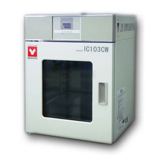
ECONOMY INCUBATOR
IC103C/103CW/403C/403CW/603C/803C
IC113C/113CW/413C/413CW/613C/813C
● Thank you very much for purchasing this Yamato IC
series incubator.
● Please
read
"Warranty" before operating this unit to assure proper
operation. After reading these documents, be sure to
store them securely together with the "Warranty" in a
handy place for future reference.
Warning :
Before operating the unit, be sure to read
carefully and fully understand important
warnings in the operating instructions.
Yamato Scientific America Inc.
Model
second edition
the
"Operating
Instructions"
and
Advertisement
Table of Contents

Related Manuals for Yamato IC103CW


Summary of Contents for Yamato IC103CW
- Page 1 ECONOMY INCUBATOR Model IC103C/103CW/403C/403CW/603C/803C IC113C/113CW/413C/413CW/613C/813C second edition ● Thank you very much for purchasing this Yamato IC series incubator. ● Please read “Operating Instructions” “Warranty” before operating this unit to assure proper operation. After reading these documents, be sure to store them securely together with the “Warranty”...
-
Page 2: Table Of Contents
Table of contents 1. Safety precautions ........................1 Explanation of symbols........................1 List of symbols..........................2 Warning・Cautions..........................3 2. Before operating the unit ......................4 Precautions when installing the unit ....................4 Installation procedures・precautions ....................7 3. Names and functions of parts ....................10 Main body ............................10 Operation panel ..........................15 Explanation of characters ......................16 4. -
Page 3: Safety Precautions
1. Safety precautions Explanation of pictograms About Symbols A variety of symbols are indicated in this operation manual and on products to assure safe operation. Possible results from improper operation or disregard for these warnings are listed below. Be sure to fully understand the descriptions below before proceeding to the text. Indicates a situation which may result in death or serious injury Warning (Note 1) -
Page 4: List Of Symbols
1. Safety precautions List of symbols Warning Danger! Danger! Danger! Danger! Warnings High voltage High temperature Moving part Hazard of explosion Caution Caution for no Caution for water Cautions Electrical shock! Burning! liquid heating! leak! For water only Poisonous material Prohibitions Do not Prohibition... -
Page 5: Warning・Cautions
1. Safety precautions Warning・Cautions Warning Never operate the unit in an atmosphere containing flammable or explosive gas Never operate the unit in an atmosphere containing flammable or explosive gas. Otherwise, an explosion or a fire may result since the unit is not explosion-proof. See section “13. -
Page 6: Before Operating The Unit
2. Before operating the unit Precautions when installing the unit 1. Carefully select an installation site. Take special care not to install the unit at a place described below: ・Uneven surfaces or dirty surfaces ・Where flammable gas or corrosive gas exists ・Where the ambient temperature is 35℃... - Page 7 2. Before operating the unit Precautions when installing the unit 4. Secure sufficient ventilation for the unit. Do not operate the unit when its vent holes on the side and rear panels are covered or blocked. Internal temperature of the unit will rise, degrading the performance, and an accident, a malfunction or a fire may result.
- Page 8 2. Before operating the unit Precautions when installing the unit 7. Be sure to connect the power plug to the dedicated power distribution panel or a wall outlet. Use a power distribution panel or a wall outlet that meets the electrical capacity of the unit. Electrical IC103C/103CW AC115V 1.8A...
-
Page 9: Installation Procedures・Precautions
2. Before operating the unit Installation procedures・precautions Transportation of the product ・Lift and transport the model IC403C/403CW/413C/413CW/603C/613C by at least two people. *Take care for protrusions on the unit. ・Move the model IC803C after push two stoppers up to unlock the casters on the front side of the main unit as shown in Unlock the figure right. - Page 10 2. Before operating the unit Installation procedures・precautions ・Install shelf pegs at heights you want on the right and left shelf posts in the internal chamber of the main body. ・Completely push shelf boards by sliding to the end. *Take care to put each shelf board on correct pairs of right and left shelf pegs. ・Make sure that shelf boards will not fall nor rattle.
- Page 11 2. Before operating the unit Installation procedures・precautions Take special care for samples shown below: ①Samples that contain flammable or explosive components ・The unit is not explosion proof. Never attempt to dry or process materials that contain flammable or explosive components. ②Corrosive samples ・Take care for handling of corrosive samples.
-
Page 12: Names And Functions Of Parts
3. Names and functions of parts Main body Front view of IC103CW/113CW Control panel Door Power switch (SW) Observation Window Handle Caution Plate Rear view of IC103CW/113CW Exhaust hole Power cord... - Page 14 3. Names and functions of parts Main body Front view of IC403C/413C/603C/613C Door Inner door Caution Plate Rating plate Handle Power switch (SW) Control panel Rear view of IC403C/413C/603C/613C Exhaust port Power cord...
- Page 15 3. Names and functions of parts Main body Front view of IC403CW/413CW Door Inner door Observation Window Caution Plate Rating plate Handle Power switch (SW) Control panel Rear view of IC403CW/413CW Exhaust hole Power cord...
- Page 16 3. Names and functions of parts Main body Front view of IC803C/813C Control panel Inner door Door Power switch (SW) Exhaust hole Rating sticker Rating plate Handle Caster wheel with a stopper (For front caster wheels only) Rear view of IC803C/813C Exhaust hole Power cord...
-
Page 17: Operation Panel
3. Names and functions of parts Operation panel MEASURED TEMP. ⑥ ⑤ ℃ ⑦ ④ HEATER SET TEMP. ① ③ TIMER STOP SUBMENU ② Name Operation/action RUN/STOP key Used for starting/stoping operation. ① Used for selecting settings. ▼▲ keys ② TIMER key Key for selecting timer operation settings. -
Page 18: Explanation Of Characters
3. Names and functions of parts Explanation of characters Characters on the controller are explained in this section. Characters Identifier Name Application AStP Auto stop setting Used for setting auto stop operation. AStr Auto start setting Used for setting auto start operation. Displayed when timer operation has Time up ended. -
Page 19: Operating Procedures
4. Operating procedures List of operation modes and functions Operation modes of the unit are as shown below: № Name Description Page Turning the power switch on to enter the operation setting mode. Fixed temperature Proceed to temperature setting that uses ▼▲ keys. P.20 operation Pressing the RUN/STOP key longer to start operation, and... - Page 20 4. Operating procedures List of operation modes and functions Functions of the unit are as shown below: Name Description Page № Calibration offset function compensates any differences between the target temperature in the chamber and the Calibration Offset control temperature of the controller (sensor temperature.) P.27 function The function can compensate to either plus or minus side...
-
Page 21: Operation Mode・Function Setting Keys And Characters
4. Operating procedures Operation mode・function setting keys and characters Key operations and characters in the diagram below are used for operation mode and function settings. -
Page 22: Operating Procedures (Fixed Temperature Operation)
4. Operating procedures Operating procedures (fixed temperature operation) How to start fixed temperature operation 1.Turn the power switch ON. (Turn the power switch to “ON.”) When the power switch is turned ON, the intial values will be displayed for about four seconds, then the initial screen will appear and the current chamber temperature and the previous set temperature are displayed on each of the indicators. -
Page 23: Operating Procedures (Quick Auto Stop Operation)
4. Operating procedures Operating procedures (quick auto stop operation) Used when you want to “stop fixed temperature operation being performed automatically in several hours. Quick auto stop operation is a function to enable auto stop timer setting during operation. Procedures for quick auto 1. - Page 24 4. Operating procedures Operating procedures (quick auto stop operation) When you want to change settings, press the ▼▲ keys on When you want to correct the current screen to enter the setting mode where you can set temperature or set time, change settings.
-
Page 25: Operating Procedures (Auto Stop Operation)
4. Operating procedures Operating procedures (auto stop operation) This mode automatically stops fixed temperature operation after a certain time from its start set with the timer. Procedures for auto stop 1. Setting a stop time ① After confirming the temperature you want is set, operation Press TIMER... - Page 26 4. Operating procedures Operating procedures (auto stop operation) When you want to change settings, press the ▼▲ keys on When you want to correct the current screen to enter the setting mode where you can set temperature or set time, change settings.
-
Page 27: Operating Procedures (Auto Start Operation)
4. Operating procedures Operating procedures (auto start operation) This mode automatically starts fixed value operation after a certain time from its start set with the timer. However, operation does not stop automatically but needs to be stopped manually. Procedures for auto start 1. - Page 28 4. Operating procedures Operating procedures (auto start operation) When you want to change the set temperature during timer counting, When you want to press the ▼▲ keys during that status to switch the set temperature correct set tempera- screen to the set temperature input mode, which blinks to enable ture or set time, or change of the set temperature with the ▼▲...
-
Page 29: Useful Functions (Calibration Offset Function)
4. Operating procedures Useful functions (calibration offset function) Calibration offset function compensates any differences between Using the calibration the target temperature in the chamber and the control offset function temperature of the controller (sensor temperature.) The function can compensate in parallel to either plus or minus side for the whole temperature band of the unit. -
Page 30: Useful Function (Setting Lock Function)
4. Operating procedures Useful function (setting lock function) This function locks the set operation status. Using the lock function The temperature is set at “off” on shipping from the factory. ① Press the TIMER key (SUB MENU key) long to enter the sub menu mode. -
Page 31: Useful Function (Power Outage Compensation Function)
4. Operating procedures Useful function (power outage compensation function) The power outage compensation function returns the main Using the power outage unit operation to the resume status after recovery from compensation function power outage, or keeps the current stop status. The function is set at “on”... -
Page 32: Cautions On Handling
If smoke emerges from the unit or an odd odor is felt, immediately turn the power switch on the main unit off, turn the power supply off and contact your dealer or a Yamato sales office for inspection. Otherwise, a fire or an electrical shock may result. The user shall never attempt to repair the unit to avoid any possible dangers. - Page 33 5. Cautions on handling Caution 1. Do not step on the unit. Do not step on the unit. Otherwise, the unit may trip over or be damaged resulting in a personal injury or a malfunction. 2. Do not put or drop an object on the unit. Do not put or drop an object on the unit.
-
Page 34: Maintenance Procedures
6. Maintenance procedures Daily inspection/maintenance Be sure to perform daily inspection and maintenance to assure reliable operation of the unit. Warning Be sure to pull out the power cord unless necessary before trying to do inspection and ● maintenance works. Start these works after the device has returned to the normal temperature. -
Page 35: When The Unit Is Not To Be Used For A Long Time Or When Disposing
7. When the unit is not to be used for a long time or when disposing When the unit is not to be used for a long time or when disposing Caution Warning When the unit is not going to be used for a long When disposing the unit ●... -
Page 36: Troubleshooting
8. Troubleshooting Safety device and error codes The unit has the self diagnostic function with a controller and a separate safety device. Table below shows possible causes and measures when the safety device is triggered. [Error codes] When a functional or mechanical abnormality occurs, the alarm lamp on the control panel comes on, an error code will be displayed and the alarm buzzer sounds. -
Page 37: When A Malfunction Is Suspected
8. Troubleshooting When a malfunction is suspected If any of the symptoms below occurs Symptom Check If the power cord is connected to the power supply securely. ● Turning the MCB to on will not activate the unit. If power outage is not occurring. ●... -
Page 38: After Sales Service And Warranty
9. After sales service and warranty When requesting a repair When requesting a repair If any trouble occurs, immediately stop operation, turn the power switch off, pull out the power plug and contact your dealer or our sales office. Information necessary for requesting a repair ●... -
Page 39: Specifications
10. Specifications IC103C/103CW IC403C/403CW IC603C IC803C Model IC113C/113CW IC413C/413CW IC613C IC813C Room temperature +5℃~80℃ Operating temperature range (no load at an ambient temperature of 23℃) Temperature control ±0.5℃ (setting: 37℃) precision Temperature ±1℃ (setting: 37℃) distribution precision 0.2 kW 0.3 kW 0.4 kW 0.73 kW Heater... -
Page 40: Wiring Diagram
11. Wiring diagram IC103C/103CW/403C/403CW/603C/803C CN 1 CN 1 AC115V CO N T Symbol Part name Symbol Part name Power Switch Solid State Relay Fuse CONT Control circuit board Terminal block Display circuit board H1, 2 Heater Temp sensor... - Page 41 11. Wiring diagram IC113C/113CW/413C/413CW/613C/813C CN 1 CN 1 AC220V CO N T Symbol Part name Symbol Part name Power Switch Solid State Relay Fuse CONT Control circuit board Terminal block Display circuit board H1, 2 Heater Temp sensor...
-
Page 42: List Of Replacement Parts
12. List of replacement parts Replacement parts Symbol Part name Standard Maker Code No. Power switch C136 SJA07732 AC220V 5A SJA07733 (IC103C/113C/103CW/113CW) AC250V 10A Fuse tube (IC403C/403CW/413C/413CW/60 SJK06251 3C/613C AC250V 15A SJK06492 (IC803C/813C) T0304.01-16 Φ3.2*55*2000 DP K Thermocouple SJA14030 single CONT Control board CN40B-Y... -
Page 43: List Of Dangerous Materials
13. List of dangerous materials Never use an explosive substance a flammable substance or a substance containing them for this device. ① Nitroglycol, glycerine trinitrate, cellulose nitrate and other explosive nitrate esters ② Trinitrobenzen, trinitrotoluene, picric acid and other explosive nitro compounds ③... -
Page 44: Standard Installation Manual
14. Standard installation manual *Install the product according to the following: (Confirm separately for optional items or special specifications) Installation mgr. Judg Model Serial number Date Installation mgr. (company name) ment TOC No. Reference page of the Judg № Item Implementation method operating instruction manual ment... - Page 45 Be sure to use the unit strictly following the handling and operating instructions in this operating instruction. Yamato Scientific Chongqing Co., Ltd. assumes no responsibility for an accident or a malfunction caused by use of this product in any way not specified in this operating instruction.
Need help?
Do you have a question about the IC103CW and is the answer not in the manual?
Questions and answers