Table of Contents
Advertisement
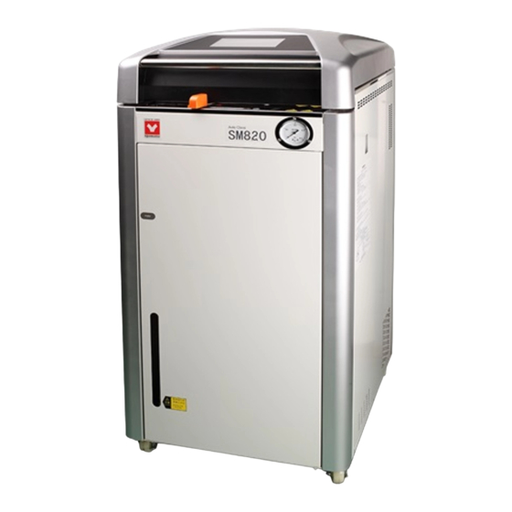
Vertical Pressure Steam Sterilizer
Thank you for purchasing SM series vertical pressure steam steriizer of Yamato
Scientific.
To use this unit properly, read this "Instruction Manual" thoroughly before using
this unit.
Keep this instruction manual around this unit for referring at anytime.
WARNING!:
Carefully read and thoroughly understand the important warning items
described in this manual before using this unit.
SM520/820
SM530/830
First Edition
Yamato Scientific America Inc.
Advertisement
Table of Contents


Need help?
Do you have a question about the SM520 and is the answer not in the manual?
Questions and answers