Table of Contents
Advertisement
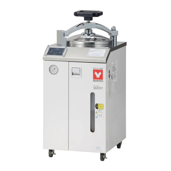
AUTOCLAVE
High Pressure Steam Sterilizer
Models SM201/301/311/501/511
Instruction Manual
● Thank you for choosing SM Series sterilizers from
Yamato Scientific Co., Ltd.
● For proper equipment operation, please read this
instruction manual thoroughly before use. Always
keep equipment documentation safe and close at
hand for convenient future reference.
Warning
Yamato Scientific America, Inc.
First Edition
: Read instruction manual warnings
and
cautions
completely before proceeding.
carefully
and
Printed on recycled paper
Advertisement
Table of Contents
Troubleshooting

Subscribe to Our Youtube Channel
Related Manuals for Yamato SM201


Summary of Contents for Yamato SM201
- Page 1 Models SM201/301/311/501/511 Instruction Manual First Edition ● Thank you for choosing SM Series sterilizers from Yamato Scientific Co., Ltd. ● For proper equipment operation, please read this instruction manual thoroughly before use. Always keep equipment documentation safe and close at hand for convenient future reference.
-
Page 3: Table Of Contents
Troubleshooting Guide ........................34 9. SERVICE & REPAIR ..........................35 10. SPECIFICATIONS ..........................36 11. WIRING DIAGRAM ..........................38 SM201 ............................... 38 SM301/501 ............................38 SM311/511 ............................39 12. LIST OF HAZARDOUS SUBSTANCES .................... 40 13. REPLACEMENT PARTS LIST......................41... -
Page 4: Safety Precautions
1. SAFETY PRECAUTIONS Explanation of Symbols A Word Regarding Symbols Various symbols are provided throughout this text and on equipment to ensure safe operation. Failure to comprehend the operational hazards and risks associated with these symbols may lead to adverse results as explained below. -
Page 5: Symbol Glossary
1. SAFETY PRECAUTIONS Symbol Glossary Warning Danger!: High Danger!: Danger!: Moving Danger!: Blast General Warning Voltage Extremely Hot Parts Hazard Caution Caution: Do Not Caution: Caution: Burn Caution: May General Caution Heat Without Electrical Shock! Hazard! Leak Water! Water! Caution: Water Caution: Toxic Only Chemicals... -
Page 6: Warning & Cautions
1. SAFETY PRECAUTIONS Warning & Cautions Warning Never operate equipment near combustible gases/fumes. Do not install or operate SM series unit near flammable or explosive gases/fumes. Unit is NOT fire or blast resistant. Negligent use could cause a fire/explosion. See “List of Hazardous Substances” (P.40). - Page 7 1. SAFETY PRECAUTIONS Warning & Cautions Equipment under pressure. DO NOT open unit lid until pressure gauge reads “0” (zero) psi. Opening while pressurized will allow high temperature, high pressure steam to abruptly escape chamber, possibly causing serious burns or other personal injury. When opening unit, always confirm pressure gauge reads “0”...
-
Page 8: Pre-Operation Procedures
2. PRE-OPERATION PROCEDURES Installation Procedures Warning 1. Choose an appropriate installation site. Install SM unit in a location with sufficient ● Do not install SM unit: space, and venilation as specified as below. ・ where flammable or corrosive gases/fumes will be generated. ・... - Page 9 Confirm that unit is properly grounded to avoid electric shock and equipment damage. Contact a ・ local dealer, certified electrician, or Yamato Sales office for local electrical requirements. ・ C onnect round terminals securely to facility terminal or to an appropriate connector.
- Page 10 Warning 10. Connect to adequate power source. Be sure unit is connected to a sufficiently Type Power Source Capacity AC115V rated power source (see table to right). SM201 13A or more single-phase AC115V SM301 15A or more single-phase AC220V SM311 9.5A or more...
- Page 11 2. PRE-OPERATION PROCEDURES Installation Procedures 15. Close the drain valve. Be sure drain valve is closed prior to operation. Forgetting to close this valve or leaving it partially open will cause water to leak from chamber, resulting in equipment damage from overheating or fire.
- Page 12 2. PRE-OPERATION PROCEDURES Installation Procedures 17. Install drain bottle. For the safety of equipment and operators, SM series units feature a safety switch, which does not allow the the sterilizer to run without the drain bottle installed. Always be sure the drain bottle is installed before each operation.
- Page 13 Upper Limit add water before level reaches the lower limit. Lower Limit SEE TABLE ON RIGHT FOR CHAMBER Requirement WATER CAPACITIES. USING MORE THAN 1900~2000ml SM201 THE MAXIMUM CAPACITY WILL RESULT 2800~3000ml SM301 IN HOT WATER OVERFLOWING FROM 2800~3000ml SM311 THE DRAIN BOTTLE.
- Page 14 2. PRE-OPERATION PROCEDURES Installation Procedures 22. Close lid. Rotate lid pivot arm to the right until it interlocks CLOSE with stop block and cannot be rotated further. Handle Turn handle clockwise in 1/4-1/2 turns until lid is Stop Block Pivot Arm sealed securely.
-
Page 15: Installation Precautions
2. PRE-OPERATION PROCEDURES Installation Precautions 1. Opening lid. OPEN Before opening unit lid, be sure that the pressure gauge reads “0 psi". Then, proceed to open slowly. If lid is opened while unit is still under pressure, hot steam will abruptly escape chamber, possibly resulting in burns or other serious personal injury, caused by sudden reflexive movements. - Page 16 2. PRE-OPERATION PROCEDURES Installation Precautions 4. Caution: HOT! During and following operation, areas surrounding the lid become very hot. Do not touch these areas. ◆ Areas in gray signify HOT surfaces, in illustration to the right. 5. Chamber lid seal. Any damage to or contaminants on the lid seal/chamber flange (area shown in gray to the right) will allow steam to escape, resulting in pressure loss and substandard...
-
Page 17: Component Names And Functions
3. COMPONENT NAMES AND FUNCTIONS Main Unit Overview 1... -
Page 18: Main Unit Overview 2
3. COMPONENT NAMES AND FUNCTIONS Main Unit Overview 2... -
Page 19: Main Unit Overview 3
3. COMPONENT NAMES AND FUNCTIONS Main Unit Overview 3... -
Page 20: Plumbing System
3. COMPONENT NAMES AND FUNCTIONS Plumbing System Solenoid Exhaust Valve Solenoid Drain Valve Chamber Pressure Gauge Safety Valve Heater 2 Sensor 1 Sensor 2 Heater 1 Drain Bottle Drain Valve Silencer... -
Page 21: Control Panel
3. COMPONENT NAMES AND FUNCTIONS Control Panel ⑤ ⑤ ⑤ ⑤ ⑦ ⑦ ⑦ ⑦ ⑥ ⑥ ⑥ ⑥ ⑬ ⑬ ⑬ ⑬ ⑭ ⑭ ⑭ ⑭ ⑧ ⑧ ⑧ ⑧ ⑪ ⑪ ⑪ ⑪ ⑨ ⑨ ⑨ ⑨ ⑫ ⑫ ⑫ ⑫ ⑩... -
Page 22: Operation Procedure
4. OPERATION PROCEDURE Mode & Function Flow 123° C max for SM201 “MODE” can be pressed at any time during the above procedure to exit settings and return to sandby screen... -
Page 23: Mode Key Overview
4. OPERATION PROCEDURE Mode Key Overview Using the MODE key. The MODE key is used to change settings/modes and to monitor settings during operation. Sterilization temperature, sterilization time, drying temperature and drying time, as well as signal on/off and keypad tone on/off functions are set/selected with the MODE key →Main display begins flashing Turn on main power switch. -
Page 24: Time & Temperature Settings
4. OPERATION PROCEDURE Time & Temperature Settings Setting sterilization mode temp/time ◆ Set the sterilization temp/time. ◆ Simply press “MODE” to cancel settings at any point during setup. ◆ Screen automatically reverts to standby (no settings saved) if keys go unpressed for more than a minute during set up. -
Page 25: Setting Alert Tone
4. OPERATION PROCEDURE Time & Temperature Settings Press “ENTER” again. Drying time can now be set. Enter desired time using ▽△. Press “ENTER”. Drying time setting is finalized. Displays automatically return to standby and flash newly set sterilization temperature and time. -
Page 26: Sterilize
4. OPERATION PROCEDURE Sterilize STERILIZE operation process Confirm the following: Is the drain valve closed? P.8 ① Is the drain filter installed? P.7 ② Is the bottom plate in place? P.7 ③ Is the drain bottle in place? P.9 ④ Does chamber have proper amount of water? P.10 ⑤... - Page 27 4. OPERATION PROCEDURE Sterilize STERILIZE process (continued) Cooling begins when sterilization time ends and heater automatically turns off. →Main display shows chamber temperature. →Sub display flashes →Sterilize process lamp lights. →Sterilize menu lamp lights. To prevent sudden boilups (bumping), the solenoid exhaust valve opens once the chamber temperature falls below the boiling point.
- Page 28 4. OPERATION PROCEDURE Sterilize & Dry STERILIZE & DRY operation process Confirm the following. ① Is the drain valve closed? P.8 ② Is the drain filter installed? P.7 ③ Is the bottom plate in place? P.7 ④ Is the drain bottle in place? P.9 ⑤...
-
Page 29: Sterilize & Dry
4. OPERATION PROCEDURE Sterilize & Dry When chamber temperature reaches temperature setting, the sterilization stage begins. →Main display shows chamber temperature. →Sub display shows remaining sterilization time. →Sterilize process lamp flashes. →Sterilize & Dry menu lamp lights. When sterilization is complete, the solenoid drain valve opens, draining all water from the chamber, and the drying heater turns on. -
Page 30: Other Functions
4. OPERATION PROCEDURE Sterilize & Dry When drying process ends, heater turns off and chamber begins cooling. →Main display shows chamber temperature. →Sub display flashes →End lamp lights. →Sterilize & Dry menu lamp lights. ◇ Press “ENTER” to clear and return to standby screen. - Page 31 4. OPERATION PROCEDURE Other Functions Pausing operation. ◇Press “ENTER”. Operation stops. Steam is purged if pressurized. →Main display shows current chamber temp. →Sub display flashes ◇Press “ENTER” twice to resume operation. →Main display flashes temperature setting. →Sub display flashes time setting. Using the pressure relief button.
-
Page 32: Handling Precautions
If unit begins emitting smoke or abnormal odors for reasons unknown, turn off main power (MCB) immediately, disconnect power cable from power supply, and contact a local dealer or Yamato sales office for assistance. Continuing to operate without addressing abnormalities may cause fire or electric shock, resulting in serious injury or death. Never attempt to disassemble or repair unit. -
Page 33: Maintenance Procedure
Lid seal cleaning & replacement. The lid seal may be wiped clean with a clean damp cloth, and should be examined regularly for cracks or damage. To replace, contact a local dealer Yamato sales office for assistance. Cleaning coil heater. - Page 34 6. MAINTENANCE PROCEDURE Inspection & Maintenance Cleaning silencer SM sterilizers are equipped with a silencer, attached to the end of exhaust hose, to reduce the noise caused by purging air and steam. Remove silencer and clean once a month. A ball valve prevents water from flowing back into chamber.
-
Page 35: Extended Storage & Disposal
Dispose of or recycle this unit in a responsible and environmentally friendly manner. Yamato Scientific America, Inc. strongly recommends disassembling unit, as far as is possible, in order to separate parts and recycle them in contribution to preserving the global environment. -
Page 36: Troubleshooting
8. TROUBLESHOOTING Error Code Guide Self-diagnostics SM series sterilizers feature self-diagnostic circuitry to monitor operation. In the event of a malfunction, a flashing error code appears on the display and an alert sounds. Power to the heater is also disabled. Confirm the error code and turn off the main power switch immediately. -
Page 37: Troubleshooting Guide
Is the drain bottle overfilled? ・ Operation does not start from ・ Is drain bottle in position? stand-by. Loud noise during air purge. ・ Is the silencer installed correctly? ◆ For further technical assistance, contact Yamato Scientific at (800) 292-6286... -
Page 38: Service & Repair
Requests for Repair When a problem occurs, terminate operation immediately, turn off main power switch (MCB) and disconnect power cable. Contact a local dealer or Yamato sales office for assistance. The following information is required for all repairs. ● Model name ●... -
Page 39: Specifications
10. SPECIFICATIONS SM201/301/501 Model SM201 SM301 SM501 System Automatic high pressure steam sterilizer 105℃~123℃ 105℃~128℃ 105℃~128℃ Sterilization Temperature Setting Range 150℃~180℃ Drying Maximum Operational Pressure 0.18MPa (26.1psi) 0.2MPa (29.0psi) 0.2MPa (29.0psi) AC115V 13A AC115V 15A AC115V 15A Power Requirement (50/60Hz) - Page 40 10. SPECIFICATIONS SM311/511 Model SM311 SM511 System Automatic High pressure steam sterilizer Temperature Sterilization 105° C~128° C Setting Range Drying 150° C~180° C Maximum Operational Pressure 0.2MPa (29.0psi) Power Requirement AC220V 9.5A (50/60Hz) Control Unit HiTec IV CR Type Microprocessor Control Sensor 1 (Chamber Temp.) Pt100Ω...
-
Page 41: Wiring Diagram
11. WIRING DIAGRAM SM201 M CB + + AC115V - SW 2 - PLANAR PI O M V2 M V1 SW 1 TI M E-UP O UTPUT ALARM O UTPUT TEM P. O UTPUT SM301/501 M CB SSR-01A + +... -
Page 42: Sm311/511
11. WIRING DIAGRAM SM311/511 M CB + + AC220V - SW 2 - X2-1 PLANAR X2-2 PI O M V2 M V1 SW 1 TI M E-UP O UTPUT ALARM O UTPUT TEM P. O UTPUT ◆ Dashed line indicates optional items Wiring diagram glossary Symbol Description... -
Page 43: List Of Hazardous Substances
12. LIST OF HAZARDOUS SUBSTANCES Never attempt to process explosives, flammables or any items which contain explosives or flammables. ①Nitroglycol, Glycerine trinitrate, Cellulose Nitrate and other explosive nitrate esters ②Trinitrobenzen, Trinitrotoluene, Picric Acid and other explosive nitro compounds ③Acetyl Hydroperoxide, Methyl Ethyl Ketone Peroxide, Benzoyl Peroxide and other organic peroxides ④Metallic Azide, including Sodium Azide, etc. -
Page 44: Replacement Parts List
Solenoid Exhaust Valve 3020010016 AB41-02-7-C4A PT1/4 AC100V CKD (SM201/301/501) Solenoid Exhaust Valve (SM311/511) 3020020008 AB41-02-7-K4A PT1/4 AC200V CKD Solenoid Drain Valve (SM201/301/501) 3020010016 AB41-02-7-C4A PT1/4 AC100V CKD Solenoid Drain Valve (SM311/511) 3020020008 AB41-02-7-K4A PT1/4 AC200V CKD Micro Switch (for drain bottle) - Page 45 Notice ● ● ● ● Instruction manual descriptions and specifications are subject to change without notice. ● ● ● ● Yamato Scientific America will replace flawed instruction manuals (pages missing, pages out of order, etc.) upon request. Instruction Manual Autoclave High Pressure Steam Sterilizer...
Need help?
Do you have a question about the SM201 and is the answer not in the manual?
Questions and answers