Table of Contents
Advertisement
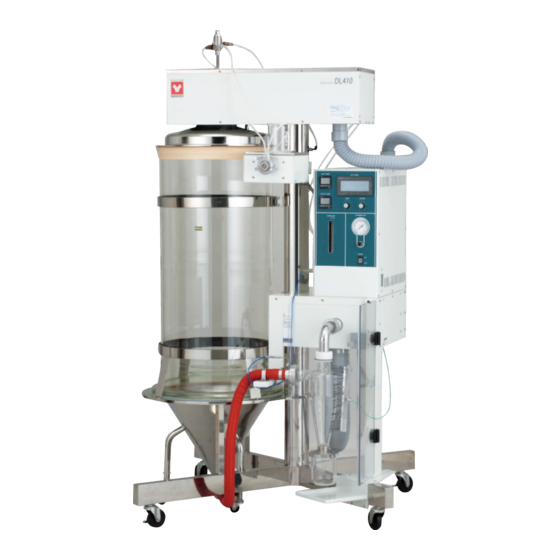
SPRAY DRYER
● Thank you for purchasing "Spray Dryer, DL410" of
Yamato Scientific Co., Ltd.
● To use this unit properly, read this "Instruction Manual"
thoroughly before using this unit.
Keep this instruction manual around this unit for referring
at anytime.
: WARNING!
Carefully read and thoroughly understand the important
warning items described in this manual before using this
unit.
Yamato Scientific America Inc.
DL410
- Version 1.3 -
Advertisement
Table of Contents

Related Manuals for Yamato DL410


Summary of Contents for Yamato DL410
- Page 1 SPRAY DRYER DL410 - Version 1.3 - ● Thank you for purchasing "Spray Dryer, DL410" of Yamato Scientific Co., Ltd. ● To use this unit properly, read this "Instruction Manual" thoroughly before using this unit. Keep this instruction manual around this unit for referring at anytime.
-
Page 2: Table Of Contents
Trouble Shooting........................28 9. After Service and Warranty ......................30 When requesting a repair......................30 10. Specification..........................31 11. Wiring diagram ...........................32 DL410 Wiring diagram........................32 12. System Chart..........................33 System Chart ..........................33 13. Operating principle ........................34 14. List of replaced parts .........................35 15. List of Dangerous Substances....................37... -
Page 3: Safety Precautions
1. Safety precautions Explanation of Symbols About the Symbols A variety of symbols are indicated in this operating instruction and on products for safe operation. Possible results from improper operation ignoring them are as follows. Be sure to fully understand the descriptions below before proceeding to the text. -
Page 4: List Of Symbols
1. Safety precautions List of symbols Warning Danger! Danger! Danger! Danger! General warnings High voltage High temperature Moving part Hazard of explosion Caution Caution for no Caution for water General cautions Electrical shock! Burning! liquid heating! leak! Poisonous For water only material Prohibitions Do not... -
Page 5: Warning・Cautions
Never use an explosive material, a flammable material or a material containing them. Using the said material will result to an explosion or an electrical shock. DL410 supports organic solvents by connecting it to the optional GAS410. Carefully read the operation manual of GAS410 and take special care for handling of organic solvents. - Page 6 1. Safety precautions Warning・Cautions Caution During a thunder storm During a thunderstorm, turn off the power key immediately, then turn off the circuit breaker and the main power. If this procedure is not followed, fire or electrical shock could occur. If an electric failure occurs, •...
-
Page 7: Before Using This Unit
Wiring equipment side is turned "OFF" when connecting power cord Black Voltage Side without fail. Note that the DL410 does not attach the power plug as standard component. Select the appropriate power plug White Voltage Side and terminal matching to the power capacity of the power... - Page 8 5. Do not use explosive or flammable substances Never use explosive substances, flammable substances and substances that include explosive or flammable ingredients in this unit. Explosion or fire may occur. DL410 supports organic solvents by connecting it to the optional GAS410. Carefully read the operation manual of GAS410 and take special care for handling of organic solvents.
- Page 9 This could cause a failure. vibration noise, cause unrespectable trouble or malfunction. DL410 SI NCE 1889 Spray Dryer INL ET TEM P KEY PANEL OUTL ET TEM P PUM P...
-
Page 10: Temperature Output Terminal
2. Before using this unit Temperature output terminal The temperature output signals for the Outlet (outlet temperature) and the Inlet (inlet temperature) are 4-20mA for the measure temperature of 40-320°C. [Current output of 4-20mA: Measured temperature of 40-320°C] Measured temp. 320℃... -
Page 11: Names And Function Of Each Part
3. Names and Function of each part Unit body Upper frame Nozzle (Head) DL410 SI NCE 1889 Spray Dryer Connecting Sample hose carrier Inner Dia.φ50 Control box INLET TEMP KEY PANEL OUTLET TEMP PUMP BLOWER Solvent delivery ATOMIZING AIR DRYING AIR... -
Page 12: Operation Panel
3. Names of parts and their function Operation Panel ⑦ ⑤ INLET TEMP KEY PANEL ④ ③ ⑥ OUTLET TEMP PUMP BLOWER ⑩ ⑧ ATOMIZING AIR DRYING AIR m /min ⑨ ② POWER ① Name Operation/Action ① Push button switch For switching on or switching off the power Connector of outlet temperature For connecting the temperature sensor... -
Page 13: Upper Frame And Control Box
3. Names of parts and their function Upper frame and control box Backside of upper frame (Head) ⑫ ⑪ NOZZLE A CN11 CN23 NOZZLE B TUBE A TUBE A TUBE A TUBE A ③ ④ ⑬ Backside of control box: ⑧... -
Page 14: Operation Procedures
4. Operation procedures Preparations before operation Place the stand on a flat surface, fixed with caster stopper. Disassemble the upper container and firm band which is fixed at the stand and the support, and take out the corrugated carton. Connect the cable from the backside of the upper frame (Head) with the connector on the backside of the control box. - Page 15 4. Operation procedures Preparations before operation Install the outlet temperature sensor on the nipple of the connecting pipe joint. Insert the (20) plug into the connector 「Outlet Temp Sensor」in front of the control box. Install the sample tube on the liquid delivery pump, and then connect it to the nipple of the (21)...
-
Page 16: Operation Method- Setting Of Drying Chamber
4. Operation procedures Operation method- Setting of drying chamber (1) Turn on the leakage protection switch on the Leakage current breaker backside of the control box. (2) Turn on the POWER switch on the operation panel. The Temperature adjuster and keystroke displays. After the power is on, the initial page of the touch panel displays for 4 seconds, and then shift to standby page. -
Page 17: Operation Method- Setting Of Cycles
4. Operation procedures Operation method- Setting of cycles (5) After the CYCLE TIME button is pressed, it will shift to the automatic operation setup page of the NEEDLE KNOCKER. After the Time Setting button is press, the Please input figures within the set range(1~60min), then press ENT to confirm If the ESC key is pressed, it will automatically jumps from the setup page.。... -
Page 18: Operation Method- Spraying Operation
4. Operation procedures Operation Method- Spraying Operation (6) Adjust the wind rate to the lowest limit, press BLOWER button, start the blower. Please use the gears to set the wind rate. Please use the gears to set the wind rate。 During operation, the indicator light of the blower is constantly on. - Page 19 4. Operation procedures Operation Method-Spraying Operation (9) After the inlet and outlet temperature has reached the expected temperature, please set the spraying pressure. Switch the pump FWD to ON, and then Set Spray Pressure & Flow infuse distilled water E. g. When the outlet temperature has reached around 90°C, set the spraying pressure to 0.1MPa.
- Page 20 4. Operation procedures Operation Method-Spaying Operation (11) After the outlet temperature is stabled, please change the sample to actual samples. At this moment, the outlet temperature will be changed, adjust the infuse speed if necessary. ~Finished operation~ (12) After the sample infusion is finished, add Set Spray Pressure &...
-
Page 21: Key Panel Indicator Light Instruction
4. Operation procedures KEY PANEL Indicator light instruction KEY PANEL Indicator light instruction As for the operation inside the KEY PANEL, the indicator light can work as a confirmation to check weather the switch is working or not. Each indicator light is on at the upper right corner of KEY PANEL. Means time setting, used when setting the operation period of the NEEDLE KNOCKER Display the operation period of NEELDE KNOCKER... -
Page 22: Handling Precautions
5. Handling Precautions Warning 1. Substances that cannot be used Never use an explosive, a flammable, or a substance that contains them. Otherwise, an explosion or a fire may result.ADL311S supports organic solvents by connecting it to the optional GAS410. Carefully read the operation manual of GAS410 and take special care for handling of organic solvents. -
Page 23: Maintenance Method
5. Handling Precautions Maintenance method (1) To disassemble the unit; please follow the step contrary to the installation procedure of outlet temperature sensor, connecting tube, and blower. Clean with water or by the other proper method. Disassemble the sample tube on the nozzle. (2)... -
Page 24: Drying Method Under Proper Condition
5. Handling Precautions Drying method under proper condition (1) Different drying sample ask for different drying condition. Spray drying method is not workable for all samples. Normally, this method is not applicable for the substance with thermo plasticity (such as low melting, thermo softening substance: sugar, fat etc.). Therefore, when using this unit for drying these substances, its recovery rate will be significantly lower. -
Page 25: Matters To Consider During Operation
5. Handling Precautions Matters to consider during operation (1) The outlet temperature should be above 100°C otherwise may result in bad performance of the blower. (2) Do not use substance containing flammable organic solvent as the sampling solvent. (3) When the heater is opened do not leave the spray nozzle inlet and the installation part of the product catcher open for long time. -
Page 26: Maintenance Method
6. Maintenance Method Daily Inspection and Maintenance Warning ● Disconnect the power cable from the power source when doing an inspection or maintenance unless needed. ● Perform the daily inspection and maintenance after returning the temperature of this unit to the normal one. - Page 27 6. Maintenance Method Daily Inspection and Maintenance Filter Cleaning ● Clean up the filter in blower periodically. 1) Open the door at the bottom of the front surface of the unit, and disconnect the hose from the blower. 2) Open the front cover by removing the two fastening plates for the cover from the upper surface of the blower, and open the front cover, and take the filter out.
-
Page 28: Long Storage And Disposal
7. Long storage and disposal When the unit is not used for long term / When disposing Caution Warning When the unit is not used for long term… When disposing… ● Turn off the earth leakage breaker and original ● Keep out of reach of children. power source for safety without fail. -
Page 29: When A Trouble Occurs
8. When a trouble occurs Safety unit and error indications The table shows possible causes of activation of the safety unit and solutions. [Error indication] When an abnormality occurs to the inlet temperature controller or the outlet temperature controller, the touch panel at the operation panel displays the error screen. When an abnormality occurred, confirm description of the error and implement appropriate solutions. -
Page 30: Trouble Shooting
8. In the Event of Failure… Trouble Shooting Symptoms Possible causes Countermeasures The POWER would ELB is turned OFF Turn the ELB ON not turn ON. Malfunction of the power supply Check the power supply circuit The wire ire short-circuited. Replace the cord Malfunction of power switch Replace the power switch... - Page 31 Magnetic valve failure for Head Replace the part. lifting Replace the part. In case of an error other than listed above occurred, turn off the power switch and primary power source immediately. Contact the shop where you purchased or nearest Yamato Scientific Service Office.
-
Page 32: After Service And Warranty
9. After Service and Warranty When requesting a repair When requesting a repair If any trouble occurs, immediately stop operation, turn the power switch off, pull out the power plug and contact your dealer, our sales office or our customer service center. Information necessary for requesting a repair ●... -
Page 33: Specification
10. Specification Machine specification Model DL410 Spraying mode Two fluid Nozzle method (Mesh diameter about Φ 0.7) Contact method of Cocurrent flow method of lower spray spray, hot wind Moisture Around 3L/Hr highest Evaporation Temperature PID Digital Temperature adjuster adjuster 2kW+2KW Stainless tube heater... -
Page 34: Wiring Diagram
11. Wiring diagram DL410 Wiring diagram... -
Page 35: System Chart
12. System Chart System Chart GAS N2 GAS IN GAS410 PRESSURE AIR IN ① Mesh tube ⑨ Liquid delivery pump ⑰ Air tank ② Dry air flow meter ⑩ Spray nozzle ⑱ Connecting tube ③ Heater ⑪ Spray air needle valve ⑲... -
Page 36: Operating Principle
13. Operating principle Operating principle 12. Please refer to system diagram。 Use containers to deliver the solvent to the spray nozzle ⑩ through the solvent delivery pump ⑨. The compressed air generated from the compressors goes through the needle valve⑪and adjusted into proper pressure, then deliver to the spray nozzle. -
Page 37: List Of Replaced Parts
14. List of replaced parts Symbol Component Name Specification Manufacturer Code № Drying chamber DL410-30431 KM11062401 Cyclone DL410-30610 2127080165 Product catcher DL410-41251 DL41041251 Spray nozzle type 1 6123SS-12-B1/4 JAUSS SJA08060 Liquid nozzle for PF2850-SS SJA07986 spraying Gas nozzle for PA64-5-SS... - Page 38 (for tube nozzle A) TSP connector 1TSF BS R0150002 (for tube nozzle B) internal thread ball valve SUS304 1/4 SJA24379 (Manual valve) DL410-40540 Suction filter LG00000394 For air intake Remarks: The item with ※ symbol means it is a consumable.
-
Page 39: List Of Dangerous Substances
Never use explosive substances, flammable substances and substances that include explosive or flammable ingredients in this unit. Otherwise explosion or fire may result DL410 supports organic solvents by connecting it to the optional GAS410. Carefully read the operation manual of GAS410 and take special care for handling of organic solvents. - Page 40 Responsibility Please follow the instructions in this document when using this unit. Yamato Scientific has no responsibility for the accidents or breakdown of device if it is used with a failure to comply. Never conduct what this document forbids. Unexpected accidents or breakdown may result in.
Need help?
Do you have a question about the DL410 and is the answer not in the manual?
Questions and answers