Table of Contents
Advertisement
Quick Links
Low Temperature
Constant-Temperature Chamber
Air Jacket System
Instruction Manual
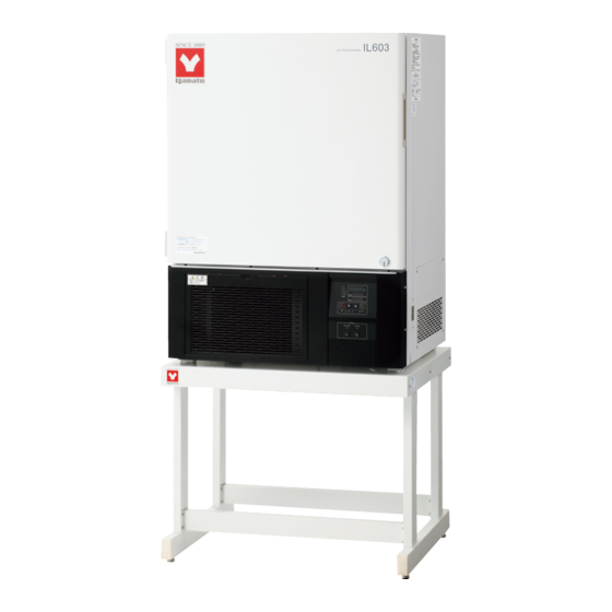
● Thank you very much for purchasing this Yamato
IL603 low temperature constant-temperature chamber.
● Please
"Warranty" before operating this unit to assure proper
operation. After reading these documents, be sure to
store them securely together with the "Warranty" at a
handy place for future reference.
Warning
Yamato Scientific America Inc.
Model IL603
First edition
read
the
"Operating
: Before operating the unit, be sure
to
read
understand important warnings in
the operating instructions.
Santa Clara,CA
Instructions"
carefully
and
and
fully
Printed on recycled paper.
Advertisement
Table of Contents

Subscribe to Our Youtube Channel
Related Manuals for Yamato IL603


Summary of Contents for Yamato IL603
- Page 1 Low Temperature Constant-Temperature Chamber Air Jacket System Model IL603 Instruction Manual First edition ● Thank you very much for purchasing this Yamato IL603 low temperature constant-temperature chamber. ● Please read “Operating Instructions” “Warranty” before operating this unit to assure proper operation.
-
Page 2: Table Of Contents
Contents 1. Safety precautions ..............1 Explanation of pictograms ............. 1 List of symbols ............... 2 Warning・Cautions ..............3 2. Before operating the unit ............4 Precautions when installing the unit ............. 4 Installation procedures/precautions ............8 About defrosting of the freezer ............10 3. -
Page 3: Safety Precautions
1. Safety precautions Explanation of pictograms About pictograms A variety of pictograms are indicated in this operating instruction and on products for safe operation. Possible results from improper operation ignoring them are as follows. Be sure to fully understand the descriptions below before proceeding to the text. -
Page 4: List Of Symbols
1. Safety precautions List of symbols Warning Danger!: High Danger!: High Danger!: Moving Danger!: Hazard General warnings voltage temperature part of explosion Caution Caution for no Caution for water General cautions Electrical shock! Burning! liquid heating! leak! Poisonous For water only material Prohibitions Do not... -
Page 5: Warning・Cautions
1. Safety precautions Warning・Cautions Warning Never operate the unit in an atmosphere containing flammable or explosive gas Never operate the unit in an atmosphere containing flammable or explosive gas. Otherwise, an explosion or a fire may result since the unit is not explosion-proof. See section “13. -
Page 6: Before Operating The Unit
2. Before operating the unit Precautions when installing the unit 1. Carefully select an installation site. Take special care not to install the unit at a place described below: ・ Uneven surfaces or dirty surfaces ・ Where flammable gas or corrosive gas exists ・... - Page 7 2. Before operating the unit Precautions when installing the unit 4. Secure sufficient ventilation for the unit. Do not operate the unit when its side panels and vent holes are blocked. Internal temperature of the unit will rise degrading the performance and an accident, a malfunction or a fire may result.
- Page 8 Use a power distribution panel or a wall outlet that meets the electrical capacity of the unit. Electrical capacity: IL603 115V AC 11.5A * When the unit will not start even when you turn the Electric Leakage Breaker to “ON”, check for low main voltage or if the unit is connected to the same power supply line as other devices and connect it to another line if necessary.
- Page 9 2. Before operating the unit Precautions when installing the unit 9. Be sure to connect the ground wire. ・ Be sure to connect the earth wire (the green core wire of the power cord) to the earth plug or the earth terminal to prevent an electric shock from electric leakage. ・...
-
Page 10: Installation Procedures/Precautions
2. Before operating the unit Installation procedures/precautions (1) Select an installation site. Make sure that the four feet completely sit on a flat surface. (2) Install a drain pan. Prepare a drain pan by yourself or purchase an optional OIL24 drain bottle for defrosting during which water comes out from the drain hose. - Page 11 2. Before operating the unit Installation procedures/precautions (4) Do not put an specimen on the bottom of the internal bath. ・Operating the unit with a specimen directly put on the bottom of the internal bath might degrade its temperature characteristics. This also may cause corrosion, damage or rust of the internal bath.
-
Page 12: About Defrosting Of The Freezer
2. Before operating the unit About defrosting of the freezer If a lot of frost is generated on the evaporator of the freezer, its freezing capacity may be compromised and the set temperature may not be maintained. The unit allows the user to monitor frosting to the evaporator through the frost observation window at the back inside the bath. - Page 13 2. Before operating the unit About defrosting of the freeze Setting a freezing operation mode (continuous, cycle) of the freezer Freezer operation mode function allows the user to set the freezer to continuous operation, cycle operation, or stop. Continuous operation is used when placing priority on the temperature control precision, in which mode the lower the set temperature becomes within the range of 0~30℃...
-
Page 14: Names And Functions Of Parts
3. Names and functions of parts Main unit Magnet packing Door Serial#/rating sticker Inner door Shelf peg/shelf board 3 sets included as standard Observation window (for monitoring frosting on the evaporator External output terminal Temperature output terminal Shelf pillar RS485 com terminal Up to 12 shelf boards accepted External alarm terminal Filter... -
Page 15: Operation Panel
3. Names and functions of parts Operation panel ⑦ ⑧ ⑫ HEATER ALARM ⑨ ⑬ AUTO STOP AUTO START SET TEMP. ⑩ FIXED TEMP. ⑭ ⑪ OVER TEMP. PROTECTOR ④ ① ENTER STOP ⑤ FIXED ② TIMER TEMP. MENU ③ ⑥... - Page 16 3. Names and functions of parts Control panel DEFROST MANUAL CYCLE ③ ④ ① ② Name Operation/Function ① MANUAL DEFROST key Used to activate the manual defrost function. ② CYCLE DEFROST key Used to activate the cycle defrost function. ③ Manual defrost lamp Lights while the manual defrost function is active.
-
Page 17: Characters Of The Controller
3. Names and functions of parts Characters of the Controller The characters controller shows are as follows: Character Identifier Name Purpose Used for setting the fixed temperature Fixed Temperature Setting Mode operation. Temperature Setting Used for setting the temperature. AStP Auto Stop Setting Used for setting the auto stop operation. -
Page 18: Operation Method
4. Operation Method Operation Mode and Function List The operation modes of the unit are as follows. Name Description Page Pressing the FIXED TEMP key enters into the fixed temperature operation setting mode. Fixed Temperature Pressing it again enters into the temperature setting mode. P.23 Operation The "▲▼"... - Page 19 4 to 20 mA. The function to allow communication between the VS3 controller and a personal computer or another unit. An optional RS485-RS232C conversion adapter RS485 Communication is required for external communication. P.38 Function A sample program is uploaded on our website. http://www.yamato-net.co.jp/support/program/index.ht...
- Page 20 The model IL603 has an observation window inside the bath to allow the operator to check how much the evaporator is frosted. The frosting speed will differ depending on the actual conditions.
- Page 21 4. Operation Method Operation Mode and Function List № Name Description There are two freezer operation modes: continuous operation and cycle operation and you can select an operation mode you want by setting the freezer operation mode function. See “Using the freezer operation mode function” on P.33. ・...
-
Page 22: Operation Mode, Function Setting Key, And Characters
4. Operation Method Operation Mode, Function Setting Key, and Characters The operation mode setting and function setting use the key operation and characters show in the following figure. Breaker ON Timer Fixed temp. Function operation setting operation FIXED TIMER TEMP. MENU Overheat preventive Calibration offset... -
Page 23: Setting Of Overheating Prevention Device
4. Operation Method Setting of Overheating Prevention Device The unit has the overheating prevention device (manual reset) that consists of independent temperature measurement circuit, CPU, sensor and output circuit (it shares power source, display, and key input with the controller) in addition to the automatic overheating prevention function (auto reset) in the controller. - Page 24 4. Operation Method Setting of Overheating Prevention Device Temperature setting procedure 1. Turn on the power (turn on the breaker in front) The default value is displayed for about four seconds after turning on the power. The screen then displays the initial HEATER setting.
-
Page 25: Fixed Temperature Operation
4. Operation Method Fixed Temperature Operation In this mode, the unit starts to operate by pressing RUN/STOP key and continues operating at the set temperature until RUN/STOP key is re-pressed, as shown in the figure below. 温度(℃) TEMP SV:温度設定値 SV: Set Temp. 時間(t )... - Page 26 4. Operation Method Fixed Temperature Operation 4. Start operation HEATER ALARM Press the orange RUN/STOP key for about one second. AUTO STOP The unit starts operation and the blinking FIXED TEMP SET TEMP. AUTO START lamp lights on FIXED TEMP. OVER TEMP.
-
Page 27: Quick Auto Stop Operation
4. Operation Method Quick Auto Stop Operation This operation is used to specify the period up to automatic stop, i.e., sets the auto stop timer during operation. Quick auto stop 1. Set the time up to stop during fixed temperature operation procedure operation ①... - Page 28 4. Operation Method Quick Auto Stop Operation To correct or check setting… Changing the setting temperature during operation is possible by pressing the FIXED TEMP key. Press the ENTER key after changing the setting. Changing the setting time during operation is possible by pressing the TIMER key.
-
Page 29: Auto Stop Operation
4. Operation Method Auto Stop Operation In this mode, the unit automatically comes to a stop after the set period passes away from the start of fixed-value operation according to timer setting, as shown in the figure below. 温度(℃) TEMP SV :温度設定値... - Page 30 4. Operation Method Auto Stop Operation Timer function: The maximum setting time is "999 hours and 50 minutes". The time can be set in increments of a minute under 99 hours and 59 minutes. It can be set in increment of ten minutes over 100 hours. The "▼▲"can change the setting time quickly when it is pressed continuously.
-
Page 31: Auto Start Operation
4. Operation Method Auto Start Operation In this mode, the unit automatically starts to operate after the set period passes away from the start of fixed-value operation according to timer setting, as shown in the figure below. However, it does not automatically come to a stop and must be manually deactivated. - Page 32 4. Operation Method Auto Start Operation Timer function: The maximum setting time is "999 hours and 50 minutes". The time can be set in increments of a minute under 99 hours and 59 minutes. It can be set in increment of ten minutes over 100 hours. The "▼▲"can change the setting time quickly when it is pressed continuously.
-
Page 33: Calibration Offset Function
4. Operation Method Calibration Offset Function Calibration Offset Calibration offset is a function which corrects the difference between the temperature in bath and that of controller (sensor Function temperature) if arises. The function parallel corrects the difference either to the plus or minus side within the whole temperature range of unit. -
Page 34: Lock Function
4. Operation Method Lock Function To use lock function This function locks the operation status previously set. This function is set to OFF before shipment. ① Press the SUB MENU key. Select the character" HEATER ALARM "Lock" , which indicates the lock of setting value, AUTO STOP SET TEMP. -
Page 35: Freezer Operation Mode Function
4. Operation Method Freezer operation mode function Using the freezer operation mode This function enables you to set the freezer to continuous function operation or to cycle operation. ① Press the SUB MENU key and select the character HEATER ALARM rEFr which indicates the freezer operation mode AUTO STOP... -
Page 36: Temperature Rise/Fall Characteristics
4. Operation Method Temperature rise/fall characteristics 温度降下上昇時間 Temperature rise/fall time 時間[分] Time [min] (reference data) -
Page 37: Introduction Of Optional Parts
One shelf board can support specimen of 15kg or more. (Withstand load of shelf board:20kg/board) Accessories ■Shelf board : 1 ■Shelf peg: 2 ・Stand(product code:211856) Ready-to-assemble type stand dedicated for IL603.(height:600mm) Accessories ■Stand: 1(ready-to-assemble) ■Philips (+) driver ・Drain bottle (product code:213467) A tank to accept drain water during defrosting externally of the unit. -
Page 38: Temperature Output Terminal
4. Operation Method Temperature Output Terminal Precautions Operate this product according to the procedure described in this Operation Manual. Failure to follow the operation procedure described herein may result in a problem. The guarantee will not apply if you operate the product in the wrong manner. CAUTION! Turn off the breaker before connecting the cables. - Page 39 4. Operation Method Temperature Output Terminal Specification The curent (mA) corresponding to the measured temperature is output. Output temperature range: -5~55℃ Output voltage: 4~20mA Temperature Output (ANALOG) Load impedance: 600Ω or less Resolution:±1℃ Connection: M4 screw terminal block ...
-
Page 40: Rs485 Communication Function
4. Operation Method RS485 Communication Function 1. Settings Relating to Communication 1.1 Communication Settings Before starting communication with the VS3 controller (hereinafter called the "unit"), set communication parameters on the personal computer. Item Communication setting Data length 8 bits Stop bit length 2 bits Parity Disabled... - Page 41 4. Operation Method RS485 Communication Function 2. Data Transmission Method Item Specification Communication standard EIA standard, complying with RS-485 Synchronization method Asynchronous communication method Communication method Half-duplex communication Transmission code ASCII code Baud rate 1200/2400/4800/9600BPS Communication distance Max. 500 m (It depends on the effect of the ambient environment.) Network Multi-drop method (up 1:31 stations) Signal wire...
- Page 42 4. Operation Method RS485 Communication Function 4.2 Message Types ■ Message types include transmission request messages from the host computer and transmission reply messages from this unit. ■ All codes from STY, address, request, identifier to ETX (except BCC) are represented by ASCII codes.
- Page 43 4. Operation Method RS485 Communication Function 4.4 Reply Message Structures 4.4.1 Reply Messages to Read Request Messages ① Start code ② Address □ □ □ □ □ □ □ □ □ □ ④ Identifier ⑤ Numeric data ① ② ⑧ ④...
- Page 44 4. Operation Method RS485 Communication Function 4.5 Description of Codes ■ The following codes from ①STX, ②address to ⑩error type are represented by ASCII codes. ■ For ASCII codes, see "8. List of ASCII Codes." ■ For conversion into ASCII codes, see "5. Communication Examples." ①...
- Page 45 4. Operation Method RS485 Communication Function ⑦ BCC This is the check code for error detection and takes the exclusive OR (EX-OR) of all characters from STX to ETX. When "Enabled" is selected for BBC check among the communication settings for the unit, this code (BCC) will not be included in the reply message. ⑧...
- Page 46 4. Operation Method RS485 Communication Function 5. Communication Examples 5.1 Read communication example Example) Request message: A request for reading PV is transmitted to the unit set at address 02. Reply message from the unit to this request message: The data of PV (00123) is returned. Read request message (transmitted from the host computer) ①...
- Page 47 4. Operation Method RS485 Communication Function 5.2 Write communication example Example) Request message: A request for setting "SV to 135" (writing 135) is transmitted to the unit set at address 03. Reply message from the unit to this request message: Information that the request message has been received is returned.
- Page 48 4. Operation Method RS485 Communication Function 6. Wire Connection Shown below is an example of multi-drop wire connection. VS3 Built-in Device AC adapter ID:01 Cable 2 CN3-3,4 KS-485 RS232C/485 converter VS3 controller Cable 1 ID:02 Cable 3 CN3-3,4 VS3 controller Up to 31 stations can be connected.
- Page 49 4. Operation Method RS485 Communication Function 7. List of Identifiers/Commands <Identifiers and set values> *1: "_" means a space. *2: The setting range depends on other parameters. (See the table shown below.) *3: A parameter with which a W command is valid during each operation (valid during operation in regular mode).
- Page 50 4. Operation Method RS485 Communication Function Other Parameters Name Identifier Command Setting Value 00000:Key lock released Key lock 00001:Key lock 00000:Stop (*3) Operation start/stop 00001:Start Operation type 00000:Fixed temperature operation selected (*3) selection 00000:Time-up (*1) Remaining hour 00001~09950:0 hours and a minute to 999 hours and 50 monitor minutes 00000:First digit = Heater output...
- Page 51 4. Operation Method RS485 Communication Function 8. List of ASCII Codes ASCII code Symbol ASCII code Numeric ASCII code - Numeric (minus) (space) ASCII code Symbol ASCII コード Symbol ASCII コード Symbol (space)
-
Page 52: Cautions On Handling
If smoke is emerges on the unit or an odd odor is felt, immediately turn the ELB on the main unit off, turn the power supply off and contact your dealer, a Yamato sales office or our customer service center for inspection. Otherwise, a fire or an electrical shock may result. The user shall never attempt to repair the unit to avoid any possible dangers. - Page 53 5. Cautions on handling Caution 1. Do not step on the unit. Do not step on the unit. Otherwise, the unit may trip over or be damaged resulting a personal injury or a malfunction. 2. Do not put or drop an object on the unit. Do not put or drop an object on the unit.
-
Page 54: Maintenance Procedures
6. Maintenance procedures Daily inspection/maintenance Be sure to perform daily inspection and maintenance to assure reliable operation of the unit. Warning ● Be sure to pull out the power cord unless necessary before trying to do inspection and maintenance works. ●... - Page 55 ※Be sure to check the operation of the ELB and the overheat preventive unit before continuous operation for an extended time or unmanned operation during nighttime. ◆If you have questions, immediately contact your dealer, one of Yamato sales offices or our customer service center.
-
Page 56: When The Unit Is Not To Be Used For A Long Time Or When Disposing
7. When the unit is not to be used for a long time or when disposing When the unit is not to be used for a long time or when disposing Caution Warning When the unit is not going to be used for a long When disposing the unit ●The Unit employs substitutive CFC. -
Page 57: Troubleshooting
8. Troubleshooting Safety device and error codes The unit has the self diagnostic function with a controller and a separate safety device. Table below shows possible causes and measures when the safety device is triggered. [Error codes] When a functional or mechanical abnormality occurs, the alarm lamp will illuminate on the control panel, an error code will be displayed on the control panel and the alarm busser will sound. -
Page 58: When A Malfunction Is Suspected
8. Troubleshooting When a malfunction is suspected If any of the symptoms below occurs Symptom Check ● Turning the ELB to on will not If the power cord is connected to the power supply securely. ● activate the unit. If power outage is occurring.. ●... -
Page 59: After Sales Service And Warranty
9. After sales service and warranty When requesting a repair When requesting a repair If any trouble occurs, immediately stop operation, turn the ELB off, pull out the power plug and contact your dealer, our sales office or our customer service center. Information necessary for requesting a repair ●... -
Page 60: Specifications
10. Specifications Product name Low temperature constant-temperature chamber Model IL603 System Natural convection with air jacket Operating temp. 0℃~50℃ range Set temp. range -5℃~55℃ ±1.0℃ JIS temperature fluctuation ±0.3℃ former JTM(Freezer (Freezer operates continuously at 37℃) Temp. adjustment operates continuously at 37℃)... -
Page 61: Wiring Diagram
Terminal block for wiring Electric Leakage Breaker(AC100V/15A/30mA) AC input Heater control relay Door heater 54W Heater inside unit (800w) SSR driving Symbol Name output Electric Leakage Breaker(AC100V/15A/30mA) Current detection (AC250V/20A) Terminal block (AC250V/20A) CT sensor input Terminal block (AC250V/20A) (Display board VS-3/4) Heater (inside unit)(800w) Heater (door)(54w) SSR (for heater control 25A) -
Page 62: Replacement Parts List
12. Replacement parts list Code № Part name Specifications Maker Silicone plug (for cable port) H436 4008-09 Aram Yamato Filter (condenser suction assembly) IL60340500 IL603-40500 Scientific... -
Page 63: List Of Dangerous Materials
13. List of dangerous materials Never use an explosive substance a flammable substance or a substance containing them for this device. ①Nitroglycol, glycerine trinitrate, cellulose nitrate and other explosive nitrate esters ②Trinitrobenzen, trinitrotoluene, picric acid and other explosive nitro compounds ③Acetyl hydroperoxide, methyl ethyl ketone peroxide, benzoyl peroxide and other organic peroxides ④Sodium azide and other metal azide... -
Page 64: Standard Installation Manual
14. Standard installation manual *Install the product according to the following: (Confirm separately for optional items or special specifications) Installation mgr.(company Model Serial number Date Installation mgr. Judgment name) TOC No. Reference page of the Judgme № Item Implementation method operating instruction manual Specifications Check for number of accessories on... - Page 65 Be sure to use the unit strictly following the handling and operating instructions in this operating instruction. Yamato Scientific Co., Ltd. assumes no responsibility for an accident or a malfunction caused by use of this product in any way not specified in this operating instruction.
Need help?
Do you have a question about the IL603 and is the answer not in the manual?
Questions and answers