Table of Contents
Advertisement
Quick Links
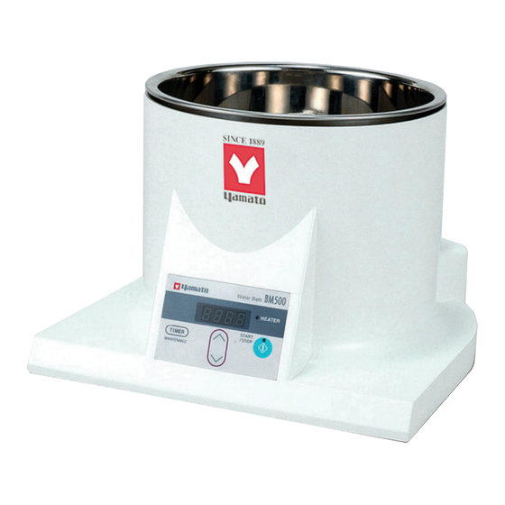
Water Bath
BM500/510
Oil Bath
BO400/410
Instruction Manual
- First Edition -
Thank you for choosing BM/BO Series
Baths from Yamato Scientific Co., Ltd.
For proper equipment operation, please
read this instruction manual thoroughly
before use. Always keep equipment
documentation safe and close at hand for
convenient future reference.
WARNING:
Read
instruction
cautions carefully and completely before
proceeding.
Yamato Scientific America Inc.
Santa Clara,CA
manual
warnings
and
Printed on recycled paper
Advertisement
Table of Contents
Troubleshooting

Subscribe to Our Youtube Channel
Related Manuals for Yamato BM510


Summary of Contents for Yamato BM510
- Page 1 BO400/410 Instruction Manual - First Edition - Thank you for choosing BM/BO Series Baths from Yamato Scientific Co., Ltd. For proper equipment operation, please read this instruction manual thoroughly before use. Always keep equipment documentation safe and close at hand for convenient future reference.
-
Page 3: Table Of Contents
Contents 1. SAFETY PRECAUTIONS ..............1 Explanation of Safety Symbols ..................1 Symbol Glossary ......................2 Warnings & Cautions ....................3 2. PRE-OPERATION PROCEDURES ............. 5 Installation Precautions & Preparations ................ 5 Prior Confirmation ......................9 3. -
Page 4: Safety Precautions
1. SAFETY PRECAUTIONS Explanation of Safety Symbols A Word Regarding Symbols Various symbols are provided throughout this text and on equipment to ensure safe operation. Failure to comprehend the operational hazards and risks associated with these symbols may lead to adverse results as explained below. -
Page 5: Symbol Glossary
1. SAFETY PRECAUTIONS Symbol Glossary Warning General Danger!: Danger!: Danger!: Danger!: Warning High Voltage Extremely Hot Moving Parts Blast Hazard Caution Caution: Caution: Do Not Caution: Burn Caution: May General Caution Electrical Shock Heat Without Hazard! Leak Water! Hazard! Water! Caution: Water Caution: Toxic Only... -
Page 6: Warnings & Cautions
1. SAFETY PRECAUTIONS Warnings & Cautions WARNING! Never operate equipment near combustible gases/fumes. Do not install or operate BM/BO series units near flammable or explosive gases/fumes. Unit is NOT fire or blast resistant. Negligent use could cause a fire/explosion. See “List of Hazardous Substances” (P.40). - Page 7 1. SAFETY PRECAUTIONS Warnings & Cautions CAUTION! DO NOT operate equipment during thunderstorm. In the event of a thunderstorm, terminate operation and turn off main power switch immediately. A direct lightning strike may cause damage to equipment, or result in fire or electric shock. Power Outages Operation is stopped when power failures occur.
-
Page 8: Pre-Operation Procedures
Use an outlet with a dedicated ground terminal for the larger capacity single-phase 100V to 120V BM500 and B0400 models. Use an outlet with a dedicated ground terminal for the single-phase 200V to 240V BM510 and B0410 models. - Page 9 2. PRE-OPERATION PROCEDURES Installation Precautions & Preparations WARNING! 3. Install in a location free of flammables and explosives. Never install near flammables or explosives. This unit is NOT fire or blast resistant. Simply switching the main power switch “ON” or “OFF” can produce a spark, which could be relayed during operation, causing a fire or explosion when near flammable or explosive fluids, chemicals or gases/fumes.
- Page 10 Use a dedicated power supply that matches electrical capacity of unit. Electrical capacity: BM500/BO400: 100 to 120V AC, 12.5A BM510/BO410: 200 to 240V AC (single phase), 6.5A NOTE) In the unlikely event that unit does not run after turning power ON, inspect whether power supply voltage of the main power is lower than specified, or whether other device(s) are sharing the same supply or line.
- Page 11 Failure to do so may result in fire or electric shock. Contact a local dealer or Yamato sales office for information about replacing power cable if it is damaged. Always connect power cable to appropriate facility outlet or terminal.
-
Page 12: Prior Confirmation
2. PRE-OPERATION PROCEDURES Prior Confirmation BM500/510 water bath operation precautions: Exercise caution in regard to the following. ① Connect unit to a power outlet having sufficient capacity. ② Do not move unit while in operation. ③ Avoid touching hot surface areas or bath fluid during operation. ④... - Page 13 2. PRE-OPERATION PROCEDURES Prior Confirmation Fluid medium for BO400/BO410 oil baths Maximum operating temperature for BO400/410 model oil baths is 180°C. Use heat-resistant dimethyl silicon oil for open system heat transfer only, and Kinematic viscosity of 50mm /s (cSt) or less. Recommended: TSF458-50 silicon oil for operating temperatures to 200°C, by Toshiba Silicon Co.
- Page 14 2. PRE-OPERATION PROCEDURES Prior Confirmation Bath container water/oil supply precautions. The bath container installed in main unit is removable for easy filling and draining. Use caution in regard to the following when adding water or oil. BM series water bath ...
-
Page 15: Component Names & Functions
3. COMPONENT NAMES & FUNCTIONS Main Unit Overview Front view Removable Bath Container Main Unit (heat-resistant ABS resin) Control Panel Rear view Power switch Power Cable Receptacle Interface for operating bath in combination with rotary evaporator model RE600/800. (Connection cable is supplied with rotary evaporator units) -
Page 16: Control Panel
3. COMPONENT NAMES & FUNCTIONS Control Panel ① ② ③ ⑦ ⑥ ⑧ ⑤ ④ Interface for operating bath in combination with rotary evaporator model RE600/800. (Connection cable is supplied with rotary evaporator units) LEAK LEAK VR600/800 Vacuum controller Name Markings Function ①... -
Page 17: Display Characters
3. COMPONENT NAMES & FUNCTIONS Display Characters Display characters used in BM/BO unit control panels are defined in the table below: Character Identifier Meaning Function/Description Timer selection menu: Selection/standby display for quick auto stop/auto AStP Auto Stop stop operation modes Selection/standby display for auto start operation AStr Auto Start... -
Page 18: Operation Procedures
4. OPERATION PROCEDURES Operation Modes & Functions BM/BO series operation modes are outlined in the table below: Name Description Page Set desired temperature with △ ▽ . Constant Temp Mode Press and hold START/STOP to start operation. Press START/STOP again to stop operation. - Page 19 4. OPERATION PROCEDURES Operation Modes & Functions BM/BO maintenance functions are outlined in the table below. To enter the maintenance menu, press and hold TIMER for four seconds. Name Description Page Keypad Lock This function prevents changes to temperature and other setting by disabling the keypad during operation.
-
Page 20: Mode & Function Flow
4. OPERATION PROCEDURES Mode & Function Flow Press & hold 4 seconds for maintenance menu Turn power ON Initial screen displayed for 4 seconds Auto Start Mode Quick Auto Stop Mode Auto Stop Mode Constant temp operation TIMER TIMER TIMER Current temp displayed AStP displayed... -
Page 21: Constant Temperature Mode
4. OPERATION PROCEDURES Constant Temperature Mode Constant Temperature mode is a general use, continuous operation mode (started/stopped manually). 1. Turn ON main power switch. Constant temperature When power switch is turned ON, display shows initial values operation procedures for about four seconds before entering standby, which shows current bath temperature in display. -
Page 22: Quick Auto Stop Mode
4. OPERATION PROCEDURES Quick Auto Stop Mode Quick Auto Stop mode adds auto stop timer function to running constant temperature mode. 1. Turn ON main power switch. Quick auto stop When power switch is turned ON, display will show initial values operation procedures for about four seconds before entering standby, which shows current bath temperature in display. - Page 23 4. OPERATION PROCEDURES Quick Auto Stop Mode 6. Stop operation Press and hold START/STOP. Operation stops. The operation and HEATER lamps turn off. Display reverts to standby (current temp). Correcting or viewing settings. Use △▽ at any time to correct or view settings. Press either △...
-
Page 24: Auto Stop Mode
4. OPERATION PROCEDURES Auto Stop Mode Auto Stop mode allows an automatic stop time to be set in advance of operation. 1. Turn ON main power switch. Auto stop When power switch is turned ON, display shows initial values operation procedures for about four seconds before entering standby, which shows current bath temperature in display. - Page 25 4. OPERATION PROCEDURES Auto Stop Mode Correcting or viewing settings. Use △▽ at any time to correct or view settings. Press either △ or ▽once to view temperature setting. Display will automatically revert to temperature reading after 4 seconds. To change the setting, continue operating △▽ until desired temperature is entered.
-
Page 26: Auto Start Mode
4. OPERATION PROCEDURES Auto Start Mode Auto Start mode allows an automatic start time to be set in advance of operation. 1. Turn ON main power switch. Auto start When power switch is turned ON, display shows initial values operation procedures for about four seconds before entering standby, which shows current bath temperature in display. - Page 27 4. OPERATION PROCEDURES Auto Start Mode 5. Stop operation Press and hold START/STOP. Operation stops. Operation and HEATER lamps go out. Display reverts to standby (current temp). Correcting or viewing settings. Use △▽ at any time to correct or view settings. Press either △...
-
Page 28: Overheat Prevention Settings
4. OPERATION PROCEDURES Overheat Prevention Settings BM/BO series units feature a built-in safety device to automatically prevent overheating, plus a thermal fuse for redundancy. How overheating prevention devices work: The main overheat prevention device is set to activate at temperature setting plus 40°C, at which point power is cut and Error 6 is displayed. -
Page 29: Keypad Lock Function
4. OPERATION PROCEDURES Keypad Lock Function Using keypad lock function This function locks the keypad, preventing unwanted interruptions or setting changes during unit operation. Use the TIMER key to set or cancel this function. ① Press and hold TIMER for about four seconds. Select [LocK] to enter menu. -
Page 30: Calibration Offset Function
4. OPERATION PROCEDURES Calibration Offset Function Set Calibration Offset The offset function works to correct discrepancies found between the bath temperature reading, as seen on the display and actual bath temperature, as taken manually, by matching temperature setting to the actual temperature. -
Page 31: Power Failure Recovery
4. OPERATION PROCEDURES Power Failure Recovery This function is to select recovery options, following a power failure. auto return or stop, Press and hold TIMER for about four seconds, then press it repeatedly until [Pon] is shown. Select [on] or [oFF] using △▽. On: continues operation when power is restored. -
Page 32: Handling Precautions
If unit begins emitting smoke or abnormal odors for reasons unknown, turn off main power switch immediately, disconnect power cable from power supply, and contact a local dealer or Yamato sales office for assistance. Continuing to operate without addressing abnormalities may cause fire or electric shock, resulting in serious injury or death. - Page 33 5. HANDLING PRECATIONS CAUTION! 4. Overnight and extended storage. Whenever unit is not in operation, stored overnight or put in storage, always turn off main power switch and disconnect power cable. 5. Use proper bath fluids. Using purified or distilled water in BM model water bath is recommended to prevent mineral deposit accumulation.
-
Page 34: Maintenance Procedures
Deformity, discoloration or other cosmetic damage may result. Wipe contaminants, excess fluids and oil from bath container with a clean, dry cloth. Clean heater and sensor with care. For further assistance, contact a local dealer or the nearest Yamato sales office. -
Page 35: Storage & Disposal
Dispose of or recycle this unit in a responsible and environmentally friendly manner. Yamato Scientific Co., Ltd. strongly recommends disassembling unit, as far as is possible, in order to separate parts and recycle them in contribution to preserving the global environment. -
Page 36: Troubleshooting
8. TROUBLESHOOTING Error Codes Possible error messages are outlined below. Power output to heater is stopped and users are notified of abnormalities by a corresponding error code on the display. Make note of the code, turn off power and call for service, if necessary. Error Code Cause/Solution Temperature sensor faulty or severed from... -
Page 37: Troubleshooting Guide
8. TROUBLESHOOTING Troubleshooting Guide Symptom Check Check to make sure power cable is securely inserted into the receptacle on back of unit Unit does power on. Check to see whether power failure is in progress. Check whether water/oil level is low. ... -
Page 38: Service & Repair
Requests for Repair When a problem occurs, terminate operation immediately, turn off main power switch and disconnect power cable. Contact a local dealer or Yamato sales office for assistance. The following information is required for all repairs. ● Model name ●... -
Page 39: Specifications
10. SPECIFICATIONS Product Name Water Bath Oil Bath Model BM500 BM510 BO400 BO410 Approx. 4 liters (water/oil added to approx. 30mm from upper lip of bath Bath capacity container) Effective bath capacity Approx. 4 liters Bath container material SUS316 Temperature control Room temp.+5°C~90°C... -
Page 40: Wiring Diagram
11. WIRING DIAGRAM BM500/510 Symbol Part name Circuit protector Terminal block Heater Thermal fuse Solid state relay PLANAR Control board K-thermocouple Display board Bath signal connector Symbol Part name Circuit protector Terminal block Heater Thermal fuse Solid state relay PLANAR Control board K-thermocouple Display board Bath signal connector... - Page 41 11. WIRING DIAGRAM BO400/410 Symbol Part name Circuit protector Terminal block Heater Thermal fuse Solid state relay PLANAR Control board K-thermocouple Display board Bath signal connector Symbol Part name Circuit protector Terminal block Heater Thermal fuse Solid state relay PLANAR Control board K-thermocouple Display board Bath signal connector...
-
Page 42: Replacement Parts
128°C G4A50128C Sakaguchi Dennetsu Heater LT00028682 120V 1440W Yamato Scientific Circuit breaker LT00037124 3120-F521-P7T1-W01J-15A Power cable LT00034726 Yamato Scientific BM510 only Part Name Code No. Specification Manufacturer Thermal fuse LT00036306 128°C G4A50128C Sakaguchi Dennetsu Heater LT00028683 240V 1440W Yamato Scientific... -
Page 43: List Of Hazardous Substances
13. LIST OF HAZARDOUS SUBSTANCES Never attempt to process explosives, flammables or any items which contain explosives or flammables. EXPLOSIVE Ethylene glycol dinitrate (nitro glycol), Glycerin trinitrate (nitroglycerine), Cellulose nitrate (nitrocellulose), and other explosive nitrate esters Trinitrobenzene, Trinitrotoluene, Trinitrophenol (picric acid), and other explosive EXPLOSIVE: nitro compounds Acetyl hidroperoxide (peracetic acid), Methyl ethyl ketone peroxide, Benzyl... -
Page 44: Setup Checklist
14. SETUP CHECKLIST * Set unit up according to the following: (Confirm optional items or special specifications separately) Installed by Installation approved Assessed Model Serial number Date (company or personnel name) Assessed № Item Procedure Instruction manual reference Specifications Confirm actual items against list of 10. - Page 45 Note ◆ Instruction manual descriptions and specifications are subject to change without notice. ◆ Yamato Scientific Co., Ltd. will replace flawed instruction manuals (pages missing, pages out of order, etc.) upon request. Instruction Manual Water Bath...
Need help?
Do you have a question about the BM510 and is the answer not in the manual?
Questions and answers