Table of Contents
Advertisement
Quick Links
Rotary Evaporator
RE201
Instruction Manual
First Edition
Thank you for choosing RE series rotary
evaporators from Yamato Scientific Co., Ltd.
For proper equipment operation, please read
this instruction manual thoroughly before
use. Always keep equipment documentation
safe and close at hand for convenient future
reference.
Warning
Read instruction manual warnings and
cautions carefully and completely before
proceeding.
Yamato Scientific America Inc.
Santa Clara,CA
:
Printed on recycled paper
Advertisement
Table of Contents

Related Manuals for Yamato RE201


Summary of Contents for Yamato RE201
- Page 1 RE201 Instruction Manual First Edition Thank you for choosing RE series rotary evaporators from Yamato Scientific Co., Ltd. For proper equipment operation, please read this instruction manual thoroughly before use. Always keep equipment documentation safe and close at hand for convenient future reference.
-
Page 3: Table Of Contents
5. TROUBLESHOOTING ................14 Troubleshooting Guide ......................14 Symptom ..........................14 6. SERVICE & REPAIR ................... 15 7. SPECIFICATIONS ..................16 8. WIRING DIAGRAM ..................17 RE201 ........................... 17 9. REPLACEMENT PARTS TABLE ..............18 10. LIST OF HAZARDOUS SUBSTANCES ............ 19... -
Page 4: Safety Precautions
1. SAFETY PRECAUTIONS Explanation of Safety Symbols A Word Regarding Symbols Various symbols are provided throughout this text and on equipment to ensure safe operation. Failure to comprehend the operational hazards and risks associated with these symbols may lead to adverse results as explained below. -
Page 5: Symbol Glossary
1. SAFETY PRECAUTIONS Symbol Glossary Warning Danger!: High Danger!: Danger!: Danger!: General Warning Voltage Extremely Hot Moving Parts Blast Hazard Caution Caution: Caution: Do Not Caution: May Caution: Burn General Caution Electrical Shock Heat Without Hazard! Leak Water! Hazard! Water! Caution: Water Caution: Toxic Only... -
Page 6: Warnings & Cautions
When using a hydraulic rotary vacuum pump or Yamato Scientific’s Handy Aspirator to decompress the evaporation system, additional use of a cold trap (Yamato model CA301 or CA800) is strongly recommended to protect vacuum pump from harmful substances and extend pump life. -
Page 7: Component Names & Functions
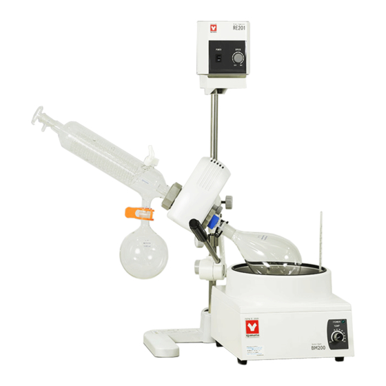
2. COMPONENT NAMES & FUNCTIONS Main Unit Overview RE201 (type A) Power Switch Control Dial Motor Assembly Stopcock Flask Removal Tool Flask Clamp Sample Feed Inlet Evaporation Flask Cooling Condenser (type A) Flask Clamp Receiving Flask Steam Duct Retainer Stand... -
Page 8: Assembly & Setup
3. ASSEMBLY & SETUP Stand I. Assemble stand.(Arm jack is combination option) Motor Support Clamp Support Rod O-Ring Lock Collar Holding Screws Lift Arm Lift Arm Handle Lock Unlock Stand Base Be sure the arrow on the lift arm assembly is pointing up. . -
Page 9: Motor & Control Units
3. ASSEMBLY & SETUP Motor & Control Units II. Install motor assembly (RE201) 1. Install motor by inserting the protruding bearing rod into the motor support clamp, making sure that the flat surface of the rod faces the holding screw. Tighten holding screw securely. -
Page 10: Steam Duct
3. ASSEMBLY & SETUP Steam Duct IV. Install steam duct. 1. Before installing the steam duct, make sure that the required O-rings are in place, inside the duct opening. If not, set them in their correct place on the glass steam duct as in figure 1 below. 2. -
Page 11: Cooling Condenser
3. ASSEMBLY & SETUP Cooling Condenser V. Condenser retainer ring, coil ring and vacuum seal placement. 2. Place the condenser retainer ring, then the coil 1. Remove the condenser retainer ring, coil ring and vacuum seal, if they have not already been removed ring over the condenser mouth flange and place from the left side (side tilted upward) of the motor. -
Page 12: Flasks
3. ASSEMBLY & SETUP Flasks IX. Install evaporation and receiving flasks. ● Evaporation Flask ● Receiving Flask 1. Rotate blue flask removal tool upward toward the 1. Place receiving end of cooling condenser or motor assembly. applicable glass component all the way into flask and 2. -
Page 13: Height Adjustment
3. ASSEMBLY & SETUP Height Adjustment XI. Adjust height (RE201). 1. Loosen lock collar holding screw. 2. Turn lift arm handle counter-clockwise to loosen; move up or down to desired height (See images 1 & 2 below). 3. When desired position is determined, turn the lever clockwise and tighten securely (See image 3 below). -
Page 14: Hose Connections
3. ASSEMBLY & SETUP Hose Connections XII. Connect hoses. Coolant Hoses 1. Remove plastic hose joints from threaded glass hose receptacles. 2. Moisten hose openings with water for easy attachment. Do not use any type of lubricating oil. 3. Push hose ends over plastic joint ends (id=9mm). 4. -
Page 15: Power
3. ASSEMBLY & SETUP Power XIII. Connect power cable. 1. Connect motor power cable to the receptacle on back of main unit. 2. Connect the power cable to 115V AC power source. Always use a grounded outlet. XIV. Setup water bath. Position water bath in front of main unit or stand. -
Page 16: Operation Procedures
4. OPERATION PROCEDURES 1. Cooling Condenser ● Condenser type A and B: Circulate water or alcohol through the cooling condenser, using Yamato Scientific CF model cooling circulators or other applicable device. ● Condenser type C Fill with dry ice or alcohol. -
Page 17: Troubleshooting
● Glass components not securely ● Reconnect components securely connected ● Vacuum hose or joint is leaking ● Apply vacuum grease to joints ●Check, reconnect hoses and/or joints If problem(s) persist, contact a local Yamato dealer or sales office for assistance. -
Page 18: Service & Repair
Requests for Repair When a problem occurs, terminate operation immediately, turn off power switch and disconnect power cable. Contact a local dealer or Yamato sales office for assistance. The following information is required for all repairs. ● Model name ● Serial Number ●... -
Page 19: Specifications
7. SPECIFICATIONS Type RE200 Rotation Speed *1 20-180rpm Drive system Worm gear Glass joints 24/40 Steam Duct, S35/20 Receiving Flask Height adjustment mechanism Lift arm Motor 25W High Torque Sparkless Induction Glass sets Type A, Type B, Type C Safety device Overcurrent protection (fuse) 16.54×11.42×33.03 (inches) Exterior dimensions... -
Page 20: Wiring Diagram
8. WIRING DIAGRAM RE201 Symbol Component Power Plug Power Switch Speed Control Pack Motor Tachogenerator Motor Condenser Set Rotation Speed Resistor Drive Socket Drive Cable Fuse (2A) -
Page 21: Replacement Parts Table
4210020010 Steam duct (wear item) O Ring 4210020012 Flask Removal Tool (wear item) Vacuum Seal RE500-40091 All types (wear item) Φ5.2×20 AC125V 2A Fuse 2100010012 RE201 Power Switch 2010010016 RE201 Speed Control Pack 1090000004 RE201 Motor 2140000022 RE201 Motor Condenser... -
Page 22: List Of Hazardous Substances
10. LIST OF HAZARDOUS SUBSTANCES Never attempt to process explosives, flammables or any items which contain explosives or flammables. ①Nitroglycol, Glycerine trinitrate, Cellulose Nitrate and other explosive nitrate esters ②Trinitrobenzen, Trinitrotoluene, Picric Acid and other explosive nitro compounds ③Acetyl Hydroperoxide, Methyl Ethyl Ketone Peroxide, Benzoyl Peroxide and other organic peroxides ④Metallic Azide, including Sodium Azide, etc. - Page 23 Always operate equipment in strict compliance to the handling and operation procedures set forth by this instruction manual. Yamato Scientific Co., Ltd. assumes no responsibility for malfunction, damage, injury or death resulting from negligent equipment use. Never attempt to disassemble, repair or perform any procedure on RE200/500 units which are not expressly mandated by this manual.
Need help?
Do you have a question about the RE201 and is the answer not in the manual?
Questions and answers