
Related Manuals for E+E Elektronik HTS801


Summary of Contents for E+E Elektronik HTS801
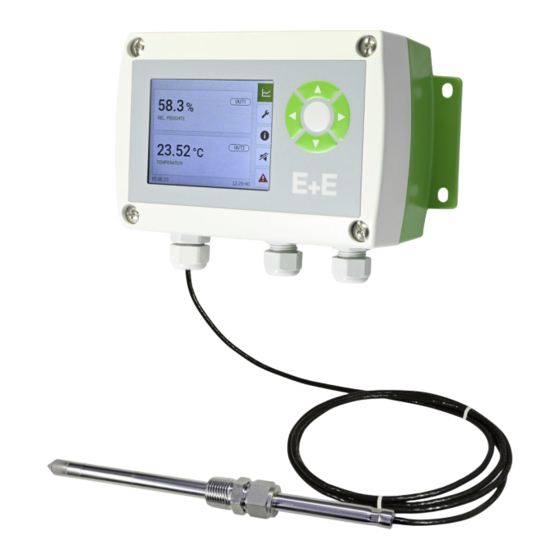
- Page 1 User Manual HTS801 Humidity and Temperature Sensor for High Humidity and Chemically Polluted Conditions...
-
Page 2: Table Of Contents
Ethernet Module - Modbus TCP (Option J4) ....................20 Dimensions ...............................22 Mounting and Installation ..........................23 Sensor Enclosure ............................23 General Information for Mounting HTS801 Sensing Probes ..............24 Remote Sensing Probe Type T5 .......................25 Remote Sensing Probe Type T7 .......................25 4.4.1. Installation at normal pressure......................... 25 4.4.2. - Page 3 User Manual HTS801 Setup and Configuration ..........................38 PCS10 Product Configuration Software ....................38 6.1.1. General ................................38 6.1.2. Simulation Mode .............................. 39 6.1.3. Analogue outputs ............................39 RS485 Digital Interface ..........................39 6.2.1. Modbus RTU Setup ............................39 6.2.2. Modbus Register Map ............................. 41 6.2.3.
-
Page 4: General Information
The user manual may not be used for the purposes of competition without the written consent of E+E Elektronik Ges.m.b.H. and may not be forwarded to third parties. Copies may be made for internal purposes. All information, technical data and diagrams included in these instructions are based on the information available at the time of writing. -
Page 5: Safety Instructions
T sensing element is exposed to an appropriate heating strategy. The use of the HTS801 in any other way than described in this manual bears a safety risk for people and the entire measurement installation and is therefore not allowed. -
Page 6: Mounting, Start-Up And Operation
Failing to follow the instructions in this user manual may lead to measurement inaccuracy and device failures. ▪. The HTS801 may only be operated under the conditions described in this user manual and within the specification included in chapter 9 Technical Data. ▪. -
Page 7: Environmental Aspects
Environmental Aspects PLEASE NOTE Products from E+E Elektronik Ges.m.b.H. are developed and manufactured in compliance with all relevant environmental protection requirements. Please observe local regulations for the disposal of the device. For disposal, the individual components of the device must be separated according to local recycling regulations. -
Page 8: Product Description
Ethernet-PoE (Modbus TCP) interface and on the alarm (relay) outputs. The configuration and the RH and T adjustment of the HTS801 can be performed with the free PCS10 Product Configuration Software. An optional 3.5” colour display with push-buttons is available for configuration and visualisation. -
Page 9: Configuration Interface
HTS801 modular polycarbonate enclosure inside view Configuration Interface The HTS801 is ready to use and does not require any configuration by the user. The factory setup of HTS801 corresponds to the type number ordered. Please refer to the datasheet at www.epluse.com/hts801. If needed, the user can change the factory setup with the ▪. -
Page 10: Operation And Heating Modes
With the ARC function foreign molecules can be evaporated from the sensing element by brief and intensive heating. All HTS801 types support the ARC function. PLEASE NOTE Before a recalibration is done after an ARC cycle, reconditioning of the sensing element is recommended. - Page 11 User Manual HTS801 The ARC parameters can be configured via PCS10 or display and push-buttons: Heating duration: Defines the time in which the monolithic measurement cell is intensively heated. A heating time of at least 20 minutes (20 min = factory setting) is recommended if chemical pollution has occurred.
-
Page 12: Condensation Guard (Cg) Against Temporary Condensation
User Manual HTS801 3.4.3. Condensation Guard (CG) against Temporary Condensation Temporary condensation on the sensing element in highly humid environments is eliminated when a specified RH set point (factory setting: acc. to order code) is reached. By intensive heating of the sensing element for 10 seconds occurring dew is evaporated. -
Page 13: High Humidity Guard
The dual heating system of the HTS801 prevents both: condensation on the RH sensing element and on the probe body by a regulated heating strategy. This leads to very short response time and fast recovery after condensing conditions. - Page 14 User Manual HTS801 CONFIGURATION HINT Display alarms can be configured via display and push-buttons only. Configuration is to be done in the “Display settings” menu. The.HTS801.display.also.includes.a.data.logger.with.a.storage.capacity.of.20 000.values.per.measurand.or. calculated quantity. During the first 5 seconds after display start-up, the data logger and the configuration menu are initialized.
-
Page 15: Rapidx Smart Probe (Option Pc7)
3.5.2. rapidX Smart Probe (Option PC7) The HTS801 with PC7 option features the intelligent pluggable rapidX probe. The rapidX smart probe enables a plug-and-play probe exchange during operation without any configuration, adjustment or calibration. The sensing element data of the rapidX smart probe is determined in the E+E RH factory calibration systems. Upon connection to the HTS801, the probe automatically uploads its specific parameters to the HTS801 electronics. -
Page 16: Arc Module (Option Am1)
For Type T17 only the RH probe is exchangeable. The T probe is fixed. 3.5.3. ARC Module (Option AM1) The additional circuit board located in the lower part of the HTS801 enclosure offers the possibiliy to start the ARC heating function with external signal. Fig. 14... -
Page 17: Alarm Module (Option Am2)
User Manual HTS801 3.5.4. Alarm Module (Option AM2) The module offers two freely configurable relay outputs for alarm or control purposes. Various operation modes are available including switch hysteresis, switch window and error indication. The error modes can be configured independently from each other. The measurands at the outputs as well as switching points, hysteresis and the normal.state.(standard./.inverted).can.be.set.via.PCS10.Product.Configuration.Software.or.using.the.push-... - Page 18 User Manual HTS801 RH [%] Switching point 2 Hysteresis 2 Switching point 1 Hysteresis 1 open Terminal 1-2 / 4-5 Normal state: Standard closed open Terminal 2-3 / 5-6 Normal state: Standard closed Fig. 18 Example window mode on both alarm outputs using normal state standard Additionally, detected errors are signaled at the alarm output.
-
Page 19: Integrated Power Supply 100 - 240 V Ac (Option Am3)
User Manual HTS801 WARNING The metal enclosure must be grounded during operation. National regulations for installation must be observed! Switch Load 250.V.AC./.6.A Max. switch load 28.V.DC./.6.A Min. switch load 12.V./.100.mA Tab. 1 Maximum and minimum switch loads WARNING No overcurrent and short circuit protection. Both relays shall be connected to either high oder low voltage. -
Page 20: Rs485 Module - Modbus Rtu (Option J3)
User Manual HTS801 3.5.6. RS485 Module - Modbus RTU (Option J3) Up to 32 HTS801 sensors with Modbus RTU interface can be connected in an RS485 bus system (1 unit load). Slave n Slave 2 (max. 32) Slave 1 Slave 3 Modbus RTU Master Fig. 22... - Page 21 ▪. HTTP-Webserver: Port 80 For a quick communication check, enter the desired IP address in a web browser and connect with the HTS801 Ethernet module’s Webserver. Fig. 23 E+E net web interface screenshots Alternatively, send an ICMP echo request (“ping”) to check correct communication settings.
-
Page 22: Dimensions
User Manual HTS801 NOTICE Supported.Ethernet.standard:.802.3i/u/x.and.af. IPv6 is not supported. Dimensions Values.in.mm / inch Enclosure Polycarbonate Stainless steel 180 (7.09) 218 (8.58) 166 (6.54) 200 (7.87) 73 (2.87) 71 (2.80) 153 (6.02) 186 (7.32) 5.1 (0.20) 5.1 (0.20) Type T5 Probe Type T7 Probe Up to 180 °C (356 °F) -
Page 23: Mounting And Installation
User Manual HTS801 Type T17 Probe Type T28 Probe Pressure-tight up to 20 bar (300 psi) For meteorological applications with optional cut-in fitting code “cable length” code “cable length” code “probe length” 93 (3.66) (1.54) 1/2".ISO.or.1/2".NPT 53 (2.09) code “cable length” code “cable length”... -
Page 24: General Information For Mounting Hts801 Sensing Probes
User Manual HTS801 DIN Rail Mounting of the Polycarbonate Enclosure ▪. Mount the two DIN rail brackets onto the back section. (HA010203, to be ordered separately, see chapter 8.Spare.Parts / Accessories) ▪. Snap in the enclosure onto the DIN rail. Fig. 27 DIN rail installation General Information for Mounting HTS801 Sensing Probes PLEASE NOTE For accurate measurement it is of paramount importance to avoid T gradients along the probe. In case of large T difference between the front and the back of the probe, it is highly recommended to insert the probe completely into the process. -
Page 25: Remote Sensing Probe Type T5
Probe into separation wall the probe shall be avoided Probe into separation wall Hanging probe Fig. 28 Mounting the remote probe of HTS801-T5 The stainless steel mounting flange is not appropriate for pressure-tight mounting. For pressure-tight requirements use HTS801-T10. Remote Sensing Probe Type T7 4.4.1. -
Page 26: Pressure-Tight Installation
WARNING General safety instructions for pressure-tight installation The installation, commissioning and operation of the HTS801-T7 may be performed by qualified staff only. Special attention shall be paid to the correct installation of the probe into the process. In case of inappropriate installation there is the risk for the probe to be suddenly expulsed due to the pressure in the process. -
Page 27: Remote Sensing Probe Type T9
WARNING General safety instructions for pressure-tight installation The installation, commissioning and operation of the HTS801-T9 may be performed by qualified staff only. Special attention shall be paid to the correct installation of the probe into the process. In case of inappropriate installation there is the risk for the probe to be suddenly expulsed due to the pressure in the process. - Page 28 User Manual HTS801 CAUTION Safety instructions for pressure-tight feedthrough: Do not assemble the probe and tighten the feedthrough if the plant is under pressure. The plant must not be vented by releasing the nut (A). Use appropriate seal on conical probe threads. Never rotate the screw connection body (B) but hold the screw connection body (B) securely and turn the nut (A).
-
Page 29: Remote Sensing Probe Type T10
For direct probe installation shut-off valves shall be placed on both sides of the probe insert (see Fig. 30 Installation of the HTS801-T10 probe directly into the process). This allows the sensor probe to be easily removed for maintenance and calibration. -
Page 30: Installation Of The Probe With Ball Valve Set
User Manual HTS801 4.6.2. Installation of the Probe with Ball Valve Set The ball valve set allows for installation and removal of the probe without process interruption. For mounting into a duct, the ball valve shall be installed perpendicular to the flow direction. NOTICE The two metal sealing rings (see Fig. 31 Installation of the probe by utilizing the ball valve set) shall be replaced every time prior to re-installing the probe. -
Page 31: Remote Sensing Probes Type T17
User Manual HTS801 Removing the probe Hold firmly the probe to avoid it being suddenly expulsed when releasing the lock. Do not bend damage the probe cable. Loosen slowly the lock nut with a spanner (spanner width 24) only till the probe is pushed out by the overpressure in the process. -
Page 32: Pressure-Tight Installation
5 Electrical Connection NOTICE The electrical installation of the HTS801 shall be performed by qualified personnel only. Observe all applicable national and international requirements for the installation of electrical devices as well as for power supply according to EN 61140, class III (EU) and class 2 supply (North America). -
Page 33: Electrical Connection And Wiring Overview
User Manual HTS801 OUT 1 OUT 2 Electrical Connection and Wiring Overview 2x M16x1.5 GND RS485 EE310/EE360 - Electrical connection for stainless steel housin Option J4 Option Polycarbonate Enclosure Stainless Steel Enclosure RS485 A (=D+) Pin Assignment RS485 B (=D-) Standard Standard Option E4 Cable Standard... - Page 34 OUT 1 n.c. (PE) n.c. n.c. RS485 B phase Analogue output Powe User Manual HTS801 (=D-) Analogue output (L1) Power supply 100 - 240 V AC for s Plug for stainless steel enclosure Modbus RTU Modbus RTU Plug Power supply 100 - 240 V AC...
- Page 35 Option E12 Option E5 GND RS485 (=D-) GND RS485 (shielded) (shielded) Power s n.c. Power supply + Modbus RTU RS485 B User Manual HTS801 Modbus RTU analogue output n.c. RS485 A (=D-) n.c. RS485 A (=D+) Power su Modbus RTU (=D+)
-
Page 36: With Cable Glands
100 - 240 V AC (option AM3) and installation is not carried out correctly, there is the danger of a touch voltage. The HTS801’s stainless steel enclosure must therefore be grounded during operation. For the contact scheme in standard and inverted operation mode, please refer to Tab. 4 in chapter 5.1 Electrical Connection and Wiring Overview. -
Page 37: Integrated Power Supply 100 - 240 V Ac (Option Am3)
100 - 240 V AC (option AM3) and installation is not carried out correctly, there is the danger of a touch voltage. ectrical connection for stainless steel housing (HS2) The HTS801’s stainless steel enclosure must therefore be grounded during operation. GND RS485 (shielded) -
Page 38: Setup And Configuration
6 Setup and Configuration The HTS801 is ready to use and does not require any configuration by the user. The factory setup of HTS801 corresponds to the type number ordered. Please refer to the data sheet at www.epluse.com/hts801. If needed, the user can change the factory setup. -
Page 39: Simulation Mode
The desired RH and T values have to entered. The duration for which the values are valid has to be specified in seconds. Please also refer to chapter 6.3 Modbus RTU Example. The Simulation Mode is available for all HTS801 models. 6.1.3. - Page 40 For highest accuracy of RH related calculated parameters, the user can set the working pressure at the operating point using the “process pressure” register or PCS10. The HTS801 features a simulation mode which supports easy commissioning and enables testing of customer data acquisition and modbus communication.
-
Page 41: Modbus Register Map
Specific humidity g/kg 1247 Specific humidity gr/lb 1249 1) Register number starts from 1 2) Register address starts from 0 Tab. 8 HTS801 FLOAT32 measured data registers Humidity and Temperature Sensor for High Humidity and Chemically Polluted Conditions | 41... -
Page 42: Freely Configurable Custom Modbus Map
2) Register address starts from 0 3) Examples: For scale 100, the reading of 2550 means a value of 25.5. For scale 50, the reading of 2550 means a value of 51. Tab. 9 HTS801 FLOAT32 and INT16 measured data registers 6.2.3. Freely Configurable Custom Modbus Map It.is.possible.to.map.measured.value/status.registers.arbitrarily.in.a.block.with.up.to.20.registers.provided.for. -
Page 43: Device Status Indication
User Manual HTS801 Registers ..with these ... map to registers ..mirrored from assigned measurands ... source registers Meas. Unit Type Function code 0x10 Function code 0x03/0x04 6001 0x1770 FLOAT32 3001 0xBB8 1021 0x3FC FLOAT32 3002 0xBB9 1022 0x3FD 6002 0x1771 °C... -
Page 44: Module Status Indication
User Manual HTS801 6.2.5. Module Status Indication If a critical error occurs, all Modbus values are set to NaN (according to IEEE754 for data type FLOAT32) or to 0x8000 (INT16). It is possible to read out the module status information via Modbus register 610 (0x261). Status indicarion is bit-coded. -
Page 45: Modbus Rtu Example
User Manual HTS801 Modbus RTU Example The HTS801’s Modbus address is 230 [0xE6]. Please refer to ▪. MODBUS APPLICATION PROTOCOL SPECIFICATION V1.1b3, chapter 6: www.modbus.org/docs/Modbus_Application_Protocol_V1_1b3.pdf ▪. E+E Application Note Modbus AN0103 (available at www.epluse.com/hts801) Read the temperature (FLOAT32) T = 25.6787014007568359375 °C from register address 0x3EA: Master (e.g. PLC) HTS801 Request [Hex]: Modbus Function Starting Starting Qty. -
Page 46: Maintenance And Service
User Manual HTS801 7 Maintenance and Service Self Diagnosis and Error Messages 7.1.1. Error Messages on the Display Error Description Error Code (Display) Error Category Recommended Action Voltage out short circuit - output 1 only* Check the wiring of the outputs Current loop open - output 1 only... -
Page 47: Cleaning The Sensing Head And Filter Cap Replacement
The filter cap shall be replaced once in a while with an E+E original one. A polluted filter cap causes longer response time of the device. ▪. If needed, the sensing head can be cleaned. For cleaning instructions please see www.epluse.com/hts801. Automatic ReCovery (ARC) When capacitive humidity sensors are exposed to chemical pollution (e.g. detergent residue), the presence of foreign molecules can distort the measurement reading. - Page 48 User Manual HTS801 Menu Customer Reference value value adjustment Offset Current measured value Reference Rel. humidity Reference value value value low 2 point adjustment Reference value Current measured Temperature high value Calibration status Reset to factory calibration Fig. 44 Customer adjustment menu...
-
Page 49: Rh.and.t.adjustment.and.calibration.for.types.t5 / T9 / T10
RH and T Adjustment and Calibration for Type T7 The HTS801 with probe type T7 has a dual heating system in a single probe design to prevent both: condensation on the RH sensing element and on the probe body through a regulated heating strategy. This results in a very short response time and allows accurate measurement of the dew point temperature Td. -
Page 50: Fuse Replacement For Integrated Power Supply 100 - 240 V Ac (Option Am3)
Radiation shield for RH probe HA010502 Radiation shield for T probe HA010506 Bracket for DIN rail mounting HA010203 Wall Mounting Clip Ø12 mm (0.47”) HA010211 Ethernet module for retrofitting, polycarbonate enclosure only HA010606 Immersion well, stainless steel Ø6x135 mm (0.25 x 5.4") 1/2" ISO HA400202 1/2" NPT HA400212 1) For polycarbonate enclosure only. Two pieces are necessary for each HTS801 Humidity and Temperature Sensor for High Humidity and Chemically Polluted Conditions | 50... -
Page 51: Technical Data
User Manual HTS801 Ordering Guide HTS801 Probe (rapidX Smart Probe, PC7 option only) Description Feature Code HTS801P- Type Remote probe up to 180 °C (356 °F) Remote probe, pressure-tight up to 20 bar (300 psi) and 180 °C (356 °F) RH remote probe, pressure-tight up to 20 bar (300 psi) and 180 °C (356 °F) - Page 52 1) Deviating from 23 °C (68 °F), defined at 12 mA or 5 V, respectively 2) Appropriate for outdoor use, wet location, degree of pollution 2, overvoltage category II, altitude up to 3 000 m (9 843 ft) Digital Digital interface RS485 (HTS801 = 1 unit load) Protocol Modbus RTU Factory settings 9 600.Baud,.parity.even,.1.stop.bit,.Modbus.address.230...
- Page 53 As designated laboratory (NMI) responsible for maintaining the National Standard for humidity and temperature in Austria, E+E Elektronik represents the highest instance in humidity and temperature calibration. Humidity and Temperature Sensor for High Humidity and Chemically Polluted Conditions | 53...
-
Page 54: Conformity
User Manual HTS801 10 Conformity 10.1 Declarations of Conformity E+E Elektronik Ges.m.b.H. hereby declares that the product complies with the respective regulations listed below: European directives and standards. UK statutory instruments and designated standards. Please refer to the product page at www.epluse.com/hts801... -
Page 55: Appendix: Display Menu Structure
User Manual HTS801 11 Appendix: Display Menu Structure 11.1 Overview Menu Configuration.of.the.data.logger/graph.-.sampling.rate.|.graphs Data logging Display settings Display layout - measurands | brightness | display alarm | orientation Output.configuration.-.mode.|.measurands.|.scaling.|.error.indication Analog output Heating mode settings ARC.and.CG.configuration.-.activation.|.deactivation.|.parameters Relay.configuration.-.mode.|.set.points.|.state Alarm output* Adjustment.-.. 1 .and.2.point.humidity/temperature.adjustment.|. Customer adjustment reset to factory adjustment | calibration status Configuration.of.Modbus.RTU.data.transmission... - Page 56 User Manual HTS801 Menu Measurand 1 Display settings Temperature [°C] Temperature [°F] Measurand 2 Rel. humidity [%] Layout Vap. p. pressure [mbar] Vap. p. pressure [psi] Measurand 3 Dew point [°C] Dew point [°F] Wet bulb temp. [°C] Measurand 4 Wet bulb temp.
- Page 57 User Manual HTS801 Menu Heating mode settings Start ARC now Cancel ARC trigger At power on Cyclic Automatic ReCovery (ARC) Minutes Heating duration Seconds ARC parameters Minutes Recovery duration Seconds RH setpoint Condensation Guard Condensation Lock time (CG) Guard Fig. 51...
- Page 58 User Manual HTS801 Menu Device settings German English Language Chinese (simplified) French Date Date settings dd.mm.yy Date format mm.dd.yy yyyy-mm-dd Time Time settings hh:mm:ss Date and time Time format hh:mm Daylight saving Central europe time UTC date Date settings UTC settings...
-
Page 59: Optional Menus
Hysteresis Standard Normal state Inverted Standard Error indication Normal state Inverted * Menu only available with connected alarm module during HTS801 start-up Fig. 55 Alarm output Humidity and Temperature Sensor for High Humidity and Chemically Polluted Conditions | 59... - Page 60 User Manual HTS801 Menu Modbus settings 1200 2400 4800 Baudrate 9600 19200 38400 57600 76800 None Parity Even Stop bits Step incrementally through the range Address 1...247 Fig. 56 Modbus settings Menu IP settings Type Shows the status of the DHCP setting...
- Page 61 User Manual HTS801 Humidity and Temperature Sensor for High Humidity and Chemically Polluted Conditions | 61...
- Page 62 User Manual HTS801 Humidity and Temperature Sensor for High Humidity and Chemically Polluted Conditions | 62...
- Page 63 User Manual HTS801 Humidity and Temperature Sensor for High Humidity and Chemically Polluted Conditions | 63...
- Page 64 T +91 990 440 5400 info.in@epluse.com E+E Elektronik Italia S.R.L. T +39 02 2707 86 36 info.it@epluse.com E+E Elektronik Korea Ltd. T +82 31 732 6050 info.kr@epluse.com E+E Elektronik Corporation T +1 847 490 0520 info.us@epluse.com Version v1.0 | 08-2023 | 195246 © Copyright E+E Elektronik Ges.m.b.H. | Modification rights reserved.
Need help?
Do you have a question about the HTS801 and is the answer not in the manual?
Questions and answers