
Related Manuals for E+E Elektronik EE771


Summary of Contents for E+E Elektronik EE771
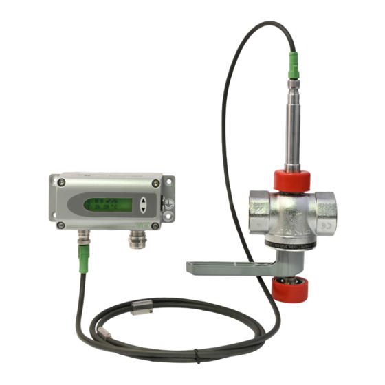
- Page 1 User Manual EE771 Flow Sensor for Compressed Air and Gases DN15 (1/2") - DN50 (2")
-
Page 2: Table Of Contents
User Manual EE771 Content General Information ............................4 Explanation of Warning Notices and Symbols .................... 4 Safety Instructions ............................. 5 1.2.1. General Safety Instructions ..........................5 1.2.2. Intended Use ..............................5 1.2.3. Mounting, Start-up and Operation ........................5 Environmental Aspects..........................6 Scope of Supply .............................. - Page 3 User Manual EE771 Configuration Software ............................32 10.1 Introduction ...............................32 10.2 Installation ..............................32 10.3 User Interface ............................34 10.4 Menu Toolbar ............................35 10.4.1. File .................................. 35 10.4.2. Transmitter ..............................35 10.4.3. Extras ................................35 10.5 Input Screen .............................35 10.5.1. Output 1, Output 2 ............................35 10.5.2.
-
Page 4: General Information
All rights reserved by E+E Elektronik Ges.m.b.H. No part of this document may be reproduced, published or publicly displayed in any form or by any means, nor may its contents be modified, translated, adapted, sold or disclosed to a third party without prior written permission of E+E Elektronik Ges.m.b.H. -
Page 5: Safety Instructions
Mounting, electrical installation, putting in operation and maintenance should only be done by qualified personnel. ▪ The use of the flow sensor EE771 in any other way than described in this manual bears a safety risk for people and the entire measurement installation and is therefore not allowed. ▪... -
Page 6: Environmental Aspects
Environmental Aspects PLEASE NOTE Products from E+E Elektronik Ges.m.b.H. are developed and manufactured in compliance with all relevant environmental protection requirements. Please observe local regulations for the disposal of the device. For disposal, the individual components of the device must be separated according to local recycling regulations. -
Page 7: Product Description
3 Product Description General The EE771 flow sensor operates on the thermal mass flow measurement principle and is suitable for measuring the flow of compressed air and gases in pipelines. Gases can be e.g. air, nitrogen, argon, CO2 or other non- corrosive and non-flammable gases. -
Page 8: Dimensions
User Manual EE771 Dimensions Values in mm (inch) EE771 compact Type T19, T20 Type T19, T20 115 (4.53) : 5.43 23.75 °C Cable gland M16x1.5 EE771 compact Type T19: flow direction right to left Type T20: flow direction left to right : 5.43... -
Page 9: Display
3) Phasing out, mixed deliveries are possible in the transition phase. Tab. 2 Dimensions Display EE771 is available with an optional 2-line liquid crystal display and soft keys. Please find details on capabilities and operation in chapter 6.3 Display / Indicator with Keypad (Optional). Flow Sensor for Compressed Air and Gases | 9... -
Page 10: Mounting And Installation
4.1.1. Process Pressure Due to its measurement principle, the thermal mass flow sensor EE771 is largely independent of the process pressure and is factory calibrated at a pressure of 7 bar (100 psi). In order to achieve the highest measurement accuracy, the slight dependence on process pressure can be compensated for in two ways: ▪... -
Page 11: Installation Position
User Manual EE771 Installation Position Make sure that the arrow on the tip of the sensing probe is pointing in the direction of the flow. Type Mounting Compact Remote Vertical Horizontal, sensor upwards Horizontal, sensor downwards Horizontal mounting, sensor across ++ ... -
Page 12: Required Length Of Straight Pipe
User Manual EE771 Required Length of Straight Pipe The flow sensor should be installed as far as possible from disturbances of the flow. The causes for disturbance of the flow are for instance reducers, elbows, T-pieces, valves, gate valves, etc. The specified measurement accuracy can be achieved only when the following straight inlet and outlet pipe lengths are installed: ▪... -
Page 13: Assembly Of The Measurement Ball Valve
User Manual EE771 Assembly of the Measurement Ball Valve NOTICE ▪ All connections must be made with appropriate sealing material on the threads. ▪ The sealing material should not change the area of the inner cross section of the pipe. It must be ensured that the connections are leak-free after installation. -
Page 14: Shut Off The Measurement Ball Valve
User Manual EE771 4.4.2. Shut Off the Measurement Ball Valve The measurement ball valve assembly allows for the installation and removal of the flow sensor within seconds, with only a very short interruption of the flow. CLOSED OPEN Fig. 4... - Page 15 User Manual EE771 WARNING Working with a pressurised piping system may cause safety risks for people and the entire measurement installation. Make sure that the measurement ball valve is shut off. Remove the transport protection cap of the head of the sensing probe.
-
Page 16: Electrical Connection
User Manual EE771 5 Electrical Connection NOTICE The power supply must be switched off before the electrical connection is made. If not observed, the electronics can be damaged as a result. Only a qualified electrical engineer may install the device. -
Page 17: Relay And Pulse Output, Internal Switching
User Manual EE771 5.1.1. Relay and Pulse Output, Internal Switching OUT x-1 OUT x-2 The relay switch and pulse outputs are potential free. 5.1.2. Connection with Optional Plug for Power Supply and Outputs (Order Code E4) Assignment OUT 2-2 OUT 1-2... -
Page 18: Setup And Configuration
Plug in the USB cable which connects the sensor to the PC. PLEASE NOTE Install the configuration software that is included in the scope of supply. The configuration software can also be downloaded from our website www.epluse.com/ee771. USB cable Blind screw cap Fig. -
Page 19: Display / Indicator With Keypad (Optional)
User Manual EE771 D isplay / Indicator with Keypad (Optional) An optional 2-line display is available for the flow sensor EE771. The display is integrated into the enclosure cover and has two softkeys for controlling the display. Line 1 Push-button - UP Maximal : 1.3 m Push-button - DOWN : 323.8 m... -
Page 20: Indication Of The Min / Max Values
User Manual EE771 6.3.3. Indication of the MIN / MAX Values Keep the DOWN key pressed for >3 seconds to indicate the MIN value. Keep the UP key pressed for >3 seconds to indicate the MAX value. For the MAX value press the push-button UP for >3 s Maximal : 1.3 m For the MIN value press the push-button DOWN for >3 s : 323.8 m T : 27.97 °C After that the several different measurement values can be indicated using the UP or DOWN keys. Keep the UP or DOWN key pressed for >3 seconds to exit the MIN / MAX mode. Rel : 1 Rel : 1 : 1.5 m... -
Page 21: Bus Output (Optional)
User Manual EE771 Bus Output (Optional) 6.4.1. M-Bus (Meter-Bus) The M-Bus (Meter Bus) is a field Bus for recording consumption data. Transmission is carried out serially on a reverse polarity protected 2-wire line. The flow sensor as an M-Bus slave requires a separate supply voltage. No specific topology (line or star) is prescribed for the cabling. -
Page 22: Modbus Rtu Register Map
The measured data is saved as 32 bit floating point values (data type FLOAT32). Depending on the measurement unit selected, measurements are saved in SI or US/GB units. The measurement unit can be changed using the configuration software. For resetting the MIN / MAX values, write 0 to the corresponding write register. For Modbus protocol setting please see Application Note AN0103 available at www.epluse.com/ee771. Flow Sensor for Compressed Air and Gases | 22... -
Page 23: Data Transmission
Write register: function code 0x06 Reset MIN/MAX value standardized flow Reset MIN/MAX value standardized volume flow Reset MIN/MAX value temperature Reset MIN/MAX value mass flow Reset MIN/MAX value pressure 1) Register number starts from 1. 2) Register address starts from 0. Tab. 6 EE771 write registers for value resetting 6.4.3. Data Transmission Factory settings Selectable values M-Bus Modbus RTU M-Bus Modbus RTU Baud rate 2 400... -
Page 24: Device Address
User Manual EE771 6.4.4. Device Address The DIP switches on the electronics board can be used to set the device address directly on-board or to switch to software configuration. 1 - ON 1 - ON 0 - OFF 0 - OFF The flow sensors are factory-set to address 1. -
Page 25: Cleaning The Sensing Element Of The Flow Sensor
User Manual EE771 Shut-off the measurement valve with the shut-off function (see chapter 4.4 Assembly of the Measurement Ball Valve). Turn off the power supply, remove the cover and disconnect the power wires from the screw terminal. Loosen the retainer nut and pull the sensor probe from the measurement section. -
Page 26: Replacement Parts / Accessories
User Manual EE771 8 Replacement Parts / Accessories Order Code Replacement Sensor Description Feature Code PE771- Type Compact ri-le, flow direction right to left Compact le-ri, flow direction left to right Remote probe Measuring range Low - 0...100 m/s (328.1 ft/s) HV31 HV31 High - 0...200 m/s (656.2 ft/s) HV33 HV33 Measurement valve for pipe... -
Page 27: Order Code Miscellaneous
User Manual EE771 PE771-T3HV31N25 Feature Code Description Type Remote probe Measuring range HV31 Low - 0...100 m/s (328.1 ft/s) Measurement valve for pipe DN25 diameter Electrical connection No code Cable gland and screw terminals Fig. 15 Replacement sensor, remote probe Order Code Miscellaneous Description Code... -
Page 28: Technical Data
User Manual EE771 9 Technical Data Measurands Volume Flow (V'n) Standard conditions Factory setting according to DIN 1343 pn = 1 013.25 mbar (14.7 psi), Tn= 0 °C (32 °F) Measuring range Standardized volume flow in Medium Pipe-diameter HV31 HV33 DN15 (1/2") 0.32...63 m /h (0.19...37.1 SCFM) 0.32...126 m /h (0.19...74.1 SCFM) DN20 (3/4") 0.57...113 m /h (0.34...66.5 SCFM) - Page 29 User Manual EE771 Digital (optional) Digital interface RS485 (EE771 = 1 unit load) Protocol Modbus RTU Factory settings 9 600 Baud, parity even, 1 stop bit, Modbus address 1 Supported Baud rates 9 600, 19 200, 38 400 and 57 600 Measured data types FLOAT32 Protocol M-Bus Factory settings 2 400 Baud, parity even, 1 stop bit, M-Bus address 1 Supported Baud rates 600, 1 200, 2 400, 4 800 and 9 600 1) Find more details about communication setting in chapter 6.4 Bus Output (Optional) and the Modbus Application Note at www.epluse.com/ee771.
- Page 30 User Manual EE771 Factory Setting of Outputs – SI Units Analogue output From Unit [0 - 10 V / 0 (4) - 20 mA] Low (HV31) High (HV32) Standardized volume flow DN15 DN20 DN25 DN32 DN40 DN50 1 400 Mass flow...
- Page 31 User Manual EE771 Factory Setting of Outputs – US Units Analogue output From Unit [0 - 10 V / 0 (4) - 20 mA] Low (HV31) High (HV32) Standardized volume flow DN15 SCFM DN20 SCFM DN25 SCFM DN32 SCFM DN40...
-
Page 32: Configuration Software
.NET Framework 3.5 SP1 can be installed using Windows Update. 10.2 Installation In order to set up a smooth installation of the configuration software of the EE771, admin authorization for the personal computer is required. ▪... - Page 33 User Manual EE771 If the EE771 configuration software and the USB driver are installed correctly, and the EE771 is connected to the personal computer via the USB interface, a connection “Silicon Labs C210x USB to UART Bridge” should have been created in the device manager.
-
Page 34: User Interface
User Manual EE771 Select the COM-port number as shown in the device manager. PLEASE NOTE These settings are done only once and at the first start of the configuration software. The settings are stored for future use. 10.3 User Interface... -
Page 35: Menu Toolbar
User Manual EE771 10.4 Menu Toolbar 10.4.1. File Menu Item Description Delete status message Deletes the status messages. Exit Closes the configuration software. 10.4.2. Transmitter PLEASE NOTE The term “Transmitter” is used synonymously with “Sensor” in this user manual. Menu... - Page 36 User Manual EE771 Measurand Here it is determined which measurand will be represented at the particular output. Units Choice of the engineering units of the selected measurand in either SI- (m/s; °C; m /h) or US-units (SFPM; °F; SCFM). PLEASE NOTE The setting “Units” on the tabs for Output 1 and Output 2 are in sync with each other. If the units are changed on one of the output tabs, automatically the units on the other output tab are changed accordingly.
- Page 37 User Manual EE771 Menu Description The hysteresis of the set point is entered as a percentage of the measuring range. [Measuring range] = high measuring value - low measuring value e.g. hysteresis Set point = 500 m /h and reset point is 450 m Hysteresis = 50 m /h = 0.5 % of measuring range...
- Page 38 User Manual EE771 Window set point 1 set point 2 Data 80 m /h = set point 2 NO (activate to close) 100 m /h = set point 1 NC (activate to open) 99 m /h = set point 1 - hysteresis 79 m /h = set point 2 - hysteresis Output Mode – Pulse If output 2 is configured for pulse, the measurand can only be consumption. The duration of the pulse and the pulse value (significance level of the pulse) can be freely configured under “Pulse”.
-
Page 39: Minimum Flow Shutdown
User Manual EE771 10.5.2. Minimum Flow Shutdown The minimum flow shutdown is switched on and off using the “active” checkbox. If the output signal is ≤ than the set “Shutdown value”, the flow sensor issues 0 on the analogue output. 10.5.3. Display If an optional display is installed, at the tab Display the following items can be entered: Drop-down input field “Display-Mode”... - Page 40 User Manual EE771 Menu Item Description Adjustment The measurand to be adjusted is selected The actual measurement value of the Measuring value transmitter is indicated. The update- interval can be set. The measurement value of the standard Reference value is entered.
-
Page 41: Measuring Values Overview
User Manual EE771 Possibility Lower adjustment point Upper adjustment point 0 ... <40 % of m.r. 60...100 % of m.r. 40 ... <50 % of m.r. 100 % of m.r. 0 % of m.r. 50 - <60 % of m.r. -
Page 42: Setting Up Process Parameters
User Manual EE771 Reset of the MIN / MAX Values The MIN / MAX values of each measurand, as stored in the flow sensor (transmitter), can be reset by checking the appropriate checkbox and subsequently clicking the “Clear MIN / MAX” button. Reset of the Consumption Meter (Totalizer) The reading of the consumption meter can be reset by clicking the “Reset meter” button. 10.5.6. Setting up Process Parameters In the tab “Process Parameters” the Process gas (medium) can be changed and the pressure compensation can be set. -
Page 43: External Pressure Sensor For Pressure Compensation
User Manual EE771 Pressure Compensation The flow sensor is factory-adjusted to 7 bar (abs). At an operating pressure other than 7 bar (abs), the error can be corrected via the pressure coefficient of +0.5% of the measured value per bar by entering the actual system pressure. -
Page 44: Conformity
User Manual EE771 11 Conformity 11.1 Declarations of Conformity E+E Elektronik Ges.m.b.H. hereby declares that the product complies with the respective regulations listed below: European directives and standards UK statutory instruments and designated standards Please refer to the product page at www.epluse.com/ee771 for the Declarations of Conformity. - Page 45 User Manual EE771 Flow Sensor for Compressed Air and Gases | 45...
- Page 46 User Manual EE771 Flow Sensor for Compressed Air and Gases | 46...
- Page 47 User Manual EE771 Flow Sensor for Compressed Air and Gases | 47...
- Page 48 T +39 02 2707 86 36 info.it@epluse.com E+E Elektronik Korea Ltd. T +82 31 732 6050 info.kr@epluse.com E+E Elektronik Corporation T +1 847 490 0520 info.us@epluse.com BA_EE771 | Version v4.6 | 02-2024 | 193296 © Copyright E+E Elektronik Ges.m.b.H. | All rights reserved.
Need help?
Do you have a question about the EE771 and is the answer not in the manual?
Questions and answers