
Subscribe to Our Youtube Channel
Related Manuals for E+E Elektronik EE75


Summary of Contents for E+E Elektronik EE75
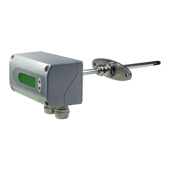
- Page 1 User Manual EE75 Highly Accurate Air / Gas Velocity Sensor for Industrial Applications...
-
Page 2: Table Of Contents
User Manual EE75 Content General Information ............................4 Explanation of Warning Notices and Symbols .................... 4 Safety Instructions ............................. 5 1.2.1 General Safety Instructions ..........................5 1.2.2 Intended Use ..............................5 1.2.3 Mounting, Start-up and Operation ........................5 Environmental Aspects..........................6 ESD Protection ............................ - Page 3 10.2 Installation ..............................21 10.2.1 Installing the USB-Interface ..........................21 10.3 Menu Items ...............................23 10.3.1 File .................................. 23 10.3.2 Help ................................. 23 10.4 EE75 Configurator ............................23 10.4.1 Start ................................23 10.4.2 Analogue ................................. 24 10.4.3 Display ................................24 10.4.4 Response Time ............................... 25 10.4.5 Cross Section ..............................
-
Page 4: General Information
All rights reserved by E+E Elektronik Ges.m.b.H. No part of this document may be reproduced, published or publicly displayed in any form or by any means, nor may its contents be modified, translated, adapted, sold or disclosed to a third party without prior written permission of E+E Elektronik Ges.m.b.H. -
Page 5: Safety Instructions
Failing to follow the instructions in this user manual may lead to measurement inaccuracy and device failures. ▪ The EE75 may only be operated under the conditions described in this user manual and within the specification included in chapter 9 Technical Data. -
Page 6: Environmental Aspects
Environmental Aspects PLEASE NOTE Products from E+E Elektronik Ges.m.b.H. are developed and manufactured in compliance with relevant environmental protection requirements. Please observe local regulations for the disposal of the device. For disposal, the individual components of the device must be separated according to local recycling regulations. -
Page 7: Product Description
▪ Type T26 with remote probe, pressure-tight to 10 bar (145psi) The IP65 / NEMA 4 rated metal enclosure facilitates easy installation and maintenance. The v and T measured data is available on two current or voltage analogue outputs. In addition to v and T values the EE75 calculates the volume flow V' in m /min or ft /min. -
Page 8: Mounting And Installation
User Manual EE75 Type T2 Duct mount Code “probe length” 12 (0.5) Type T3 Remote probe Code “probe cable length” Code “probe length” 12 (0.5) Type T26 Remote probe, pressure-tight up to 10 bar (145 psi) Code “probe cable length”... -
Page 9: Mounting Type T2 (Duct Mounting)
User Manual EE75 2. The dimensions of the mounting holes are as shown in the adjacent drawing. 3. The bottom part of the enclosure is fitted using 4 screws (not included). Max. screw diameter 4.5 mm (0.18”), for example 4.2 x 38 mm (0.17 x 1.5”) - DIN 7983H screws. -
Page 10: Mounting Type T3 (Remote Probe)
User Manual EE75 Mounting Type T3 (Remote Probe) 4.3.1 Installing the enclosure Refer to chapter 4.1 Installing the Enclosure 4.3.2 Installing the probe Refer to chapter 4.2.2 Mounting with a Flange Selected probe length (0.5) Fig. 5 Mounting flange Mounting Type T26 (Remote Probe, Pressure-tight up to 10 bar / 145 psi) 4.4.1... -
Page 11: Flow Direction
User Manual EE75 Procedure 1. Install the probe with the shut-off valves closed. Clamping ring 2. Insert the sensor probe into the process. Lock nut 3. To ensure the probe is installed securely, the lock 1/2" ISO nut must be tightened to a specified torque of... -
Page 12: Electrical Connection
User Manual EE75 Flow direction type T2 (duct mounting) Flow direction type T3 and T26 (remote probe) To be able to read off the orientation of the remote sensor head beyond the measuring line, a mark has been punched at the end of the sensing probe. This corresponds with:... -
Page 13: Connection Diagram With Optional Connections
User Manual EE75 Connection Diagram with Optional Connections Assignment OUT1 M12 Plug for supply OUT2 GND (Supply) analogue outputs GND (OUT) Front view on device Assignment M12 Socket for USB interface Vbus Not assigned Front view on device PLEASE NOTE Cable connection to the plugs should be as indicated by the numbers above. -
Page 14: Jumpers For Setting The Output Signal
EE75-TxA6 (for current output, e.g. 4 - 20 mA) EE75-TxA3 (for voltage output, e.g. 0 - 10 V) Jumpers for Setting the Velocity Response Time The EE75 allows users to set the velocity response time: Setting the velocity response time using jumpers Jumper position (refer to chapter 5.1... - Page 15 User Manual EE75 4. MIN/MAX Function The MIN / MAX function can be used to record the lowest and highest values measured for each measurand since the last reset or the last interruption of the power supply. Highest measured value: MAX 1. Select the required measurand (UP / DOWN button) 2. To display the maximum value, press the UP button and hold it down for approx. 5 s.
-
Page 16: Velocity And Temperature Calibration
Fig. 11 Incorrect installation 1-point or 2-point Calibration The EE75 sensor can be calibrated in 2 different ways 1-point v/T calibration Quick and easy option for obtaining accurate measuring results at a specific working point. 1-point calibration should only be used for very limited working ranges. -
Page 17: General Information On 2-Point V/T Calibration
▪ The high calibration point should be in the upper third of the measuring range. Calibration / adjustment must be performed using the V/T-CAL HIGH function. Example EE75 T3***HV23 - measuring range = 0 ... 2 m/s (0...400 ft/min). Low calibration point (V-CAL LOW) should be around 0.4 m/s (0...0.7). High calibration point (V-CAL HIGH) should be around 1.8 m/s (1.4...2). -
Page 18: Calibration Procedure Using Buttons On The Display Module (Optional)
User Manual EE75 6.3.1 Calibration Procedure Using Buttons on the Display Module (Optional) 1. Insert the sensor head in the temperature reference system. 2. Allow it to stabilise (min. 15 minutes). The greater the difference in temperature between the measuring probe and the reference system, the longer the required stabilisation time. -
Page 19: Maintenance
= measured value Dependency of inflow angle (α) <3 % for α <20° of inflow direction <3 % Response time t , typ. <1.5...40 s (Factory setting: 2 s, configurable via EE75 Configuration Software) Temperature (T) Measuring range -40...+120 °C Accuracy ±0.5 °C (±0.9 °F) in air at 25 °C (77 °F) at air flows ≥0.45 m/s (886 ft/min) Temperature dependency of electronics, typ. - Page 20 EN 61326-2-3 Industrial Environment FCC Part15 Class B ICES-003 Class B Configuration und adjustment EE75 Configuration Software and USB interface cable included in the scope of supply Conformity Highly Accurate Air / Gas Velocity Sensor for Industrial Applications | 20...
-
Page 21: Configuration Software
Replace and secure the upper module of the enclosure. Connect EE75 to the supply voltage (V You can now connect the EE75 to your chosen USB Port on your PC (max. transmission distance 3 m). The driver software will be installed automatically. - Page 22 See Start / Settings / Control Panel / System / Hardware / Device Manager The configuration software can now be opened by double-clicking the EE75 icon on your desktop. Specify the selected USB Port (for details, see Configuration Software, chapter 10.3.1 File) Pressing the “Read”...
-
Page 23: Menu Items
User Manual EE75 10.3 Menu Items 10.3.1 File Sub-Item Description Load Settings Opens the saved sensor configuration settings from an archive file on the PC. Save Settings Saves the displayed configuration settings in an archive file on the PC. Select COM Port Selects the USB interface used on your PC. -
Page 24: Analogue
User Manual EE75 10.4.2 Analogue The “Analog” tab allows free configuration and scaling of the two analogue outputs. Selection Fields Description The drop-down input field is used either to select a ▪ standardised output signal (0-5 V, 0-10 V, 0-20 mA, 4-20 mA) -
Page 25: Response Time
(jumper position). 10.4.5 Cross Section The EE75 allows volumetric flow to be displayed in [m³/min] or [ft³/min.] (refer to chapter 5.4 Display Module with Buttons (Optional) - Measurands). The volume is calculated based on the flow velocity measured and the cross section. Consequently, the cross sectional area of the duct must be entered in [m²] or [ft²]. -
Page 26: Probe Cable
This virtually rules out additional measuring errors due to the modified cable length. Example You order an EE75 T3***K5 (5m / 16.4ft cable length) and then cut the cable with 3m (9.8ft). The new cable length of 2m (6.6ft) should be entered and uploaded using the “Write” function. -
Page 27: Media Correction
“high calibration point” (CAL HIGH). Example EE75 T3***HV23: Measuring range = 0...2 m/s (0...400 ft/min) -> centre of measuring range = 1 m/s (200 ft/min) ▪ 0.5 m/s (100 ft/min) -> calibration point lies below 1 m/s (200 ft/min) -> CAL LOW ▪ 1.6 m/s (300 ft/min) ->... - Page 28 4. Clicking on the “Velocity calibration” button opens the menu window shown below. 5. Enter the velocity displayed by the reference system in the “Reference value” input field. 6. Clicking “Save” adjusts the EE75 measuring value with the reference value. 7. In the case of 1-point calibration, the process is now complete.
-
Page 29: Measuring Values
User Manual EE75 10.4.10 Measuring Values The configuration software allows the EE75 measuring values to be queried periodically on the “Measuring Values” index card. If the “Activate automatic Query” function is activated, all measuring values are downloaded according to the specified interval and displayed in the desingated fields. -
Page 30: Conformity
User Manual EE75 11 Conformity 11.1 Declarations of Conformity E+E Elektronik Ges.m.b.H. hereby declares that the product complies with the respective regulations listed below: European directives and standards. UK statutory instruments and designated standards. Please refer to the product page at www.epluse.com/ee75 for the Declarations of Conformity. - Page 31 User Manual EE75 Highly Accurate Air / Gas Velocity Sensor for Industrial Applications | 31...
- Page 32 T +39 02 2707 86 36 info.it@epluse.com E+E Elektronik Korea Ltd. T +82 31 732 6050 info.kr@epluse.com E+E Elektronik Corporation T +1 847 490 0520 info.us@epluse.com BA_EE75 | Version v15 | 07-2024 | 192310 © Copyright E+E Elektronik Ges.m.b.H. | All rights reserved.
Need help?
Do you have a question about the EE75 and is the answer not in the manual?
Questions and answers