Advertisement
Quick Links
advanced FLOW engineering
Instruction Manual
Make: Hyundai
Model: Avante Sport
Make: Hyundai
Model: Elantra
Make: Hyundai
Model: Elantra GT
Make: Hyundai
Model: i30
Make: Hyundai
Model: Kona
Make: Hyundai
Model: Veloster
Make: KIA
Model: Forte GT
Make: KIA
Model: K3 GT
P/N: 77-47001
®
Year: 2017-2019
Year: 2017-2020
Year: 2018-2020
Year: 2017-2020
Year: 2018-2020
Year: 2013-2020
Year: 2019-2020
Year: 2019-2020
Engine: L4-1.6L Turbo
Engine: L4-1.6L Turbo
Engine: L4-1.6L Turbo
Engine: L4-1.6L Turbo
Engine: L4-1.6L Turbo
Engine: L4-1.6L Turbo
Engine: L4-1.6L Turbo
Engine: L4-1.6L Turbo
Advertisement

Subscribe to Our Youtube Channel
Related Manuals for aFe Power 77-47001


Summary of Contents for aFe Power 77-47001
- Page 1 ® advanced FLOW engineering Instruction Manual P/N: 77-47001 Make: Hyundai Model: Avante Sport Year: 2017-2019 Engine: L4-1.6L Turbo Make: Hyundai Model: Elantra Year: 2017-2020 Engine: L4-1.6L Turbo Make: Hyundai Model: Elantra GT Year: 2018-2020 Engine: L4-1.6L Turbo Make: Hyundai Model: i30 Year: 2017-2020 Engine: L4-1.6L Turbo...
- Page 2 05-60167 Attention: aFe POWER strongly recommends upgrading the factory spark plugs to high performance spark plugs to maintain a stronger, more consistent spark and prevent any damage to your engine. During our testing we used HKS M45XL spark plugs and recommend those spark plugs or equivalent.
- Page 3 aFepower.com Page 3...
- Page 4 ® REMOVAL Figure A Refer to Figure A for Step 1. Step 1: Before installing your aFe module, you will have to place your vehicles ECU in sleep mode. In order to do this you will need to do the following: - If the engine is cold, open the hood, close the doors lock the car and wait 30 seconds.
- Page 5 REMOVAL Figure B Refer to Figure B for Steps 2-3. Step 2: Remove the (2) push clips securing the air scoop and loosen the clamp securing the intake tube to the airbox. Step 3: Remove the (3) 10mm bolts securing the airbox, then pull the airbox out of the vehicle. Page 5...
- Page 6 ® REMOVAL FUEL PRESSURE Figure C Refer to Figures C for Step 4. Step 4: Locate the MAP and T-MAP sensors. The MAP sensor is on the intake manifold. The T-MAP sensor is on the charge pipe, before the throttle body. Page 6...
- Page 7 INSTALL Figure D Refer to Figure D for Steps 5-6. Step 5: Locate then disconnect the MAP sensor connector by pressing down on the locking tab of the connector and sliding it out of the sensor. Step 6: Locate the MAP sensor jumper harness on the aFe module. The harness will be labeled “MAP”. Plug the female connector of the module into the factory MAP sensor, then the male connector of the module to the female connector of the engine harness.
- Page 8 ® INSTALL Figure E Refer to Figure E for Step 7. Step 7: Check with the pictures to make sure the connectors are correctly connected. Note: Make sure connections are fully engaged. Usually, connectors make a snapping sound when fully engaged. Page 8...
- Page 9 INSTALL Figure F Refer to Figure F for Steps 8-9. Step 8: Locate and disconnect the TMAP sensor connector, by pressing down on the locking tab of the connector, and sliding it out of the sensor. Step 9: Locate the TMAP sensor jumper harness on the aFe module. The harness will be labeled “TMAP.” Plug the female connector of the module into the factory T-MAP sensor, then the male connector of the module to the female connector of the engine harness.
- Page 10 ® INSTALL Figure G Refer to Figure G for Step 10. Step 10: Check with the pictures to make sure the connectors are correctly connected. Note: Make sure connections are fully engaged. Usually, connectors make a snapping sound when fully engaged. Page 10...
- Page 11 INSTALL Figure H Refer to Figure G for Steps 11-12. Step 11: Carefully route the switch cable behind steering wheel cover. Step 12: Mount the Switch on an open, flat surface Page 11...
- Page 12 ® INSTALL Figure I Refer to Figure I for Step 13. Step 13: Remove the (4) 10mm bolts securing the TCU under the dash, and gently lower the TCU to gain access to the firewall grommet. Do not unplug the TCU. Note: This step is specific to the vehicles equipped with an automatic transmission, wiring of the switch cable will vary for manual transmission vehicles.
- Page 13 INSTALL Figure J Refer to Figure J for Step 14. Step 14: Route the switch cable through firewall and into the engine bay. Follow the hood latch cable through the grommet into the firewall. Plug the end of the cable to the module harness. Then reinstall the TCU.
- Page 14 ® INSTALL Figure K Refer to Figure K for Steps 15-16. Step 15: Mount the module in a safe location, such as on top of the battery, using the supplied Velcro strip. Then, secure the wires and module away from any extreme heat and moving parts, with the provided ties.
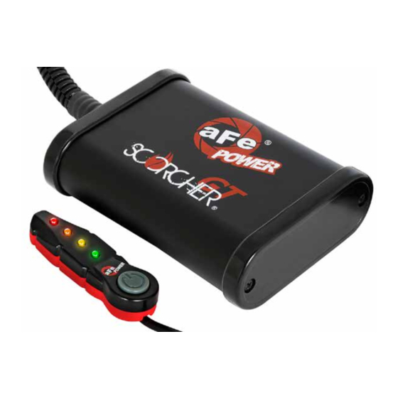
- Page 15 • Orange LED: Sport+ (91 Octane or Higher is recommended) • Red LED: Race (93 Octane or Higher is recommended) Use the grey button to select the desired setting. Power adjustments can be done at any moment. Thank you for choosing aFe POWER! Page 15...
- Page 16 ® advanced FLOW engineering, inc. 252 Granite Street Corona, CA 92879 TEL: 951.493.7100 TECH: 951.493.7185 P/N: 06-81084...
Need help?
Do you have a question about the 77-47001 and is the answer not in the manual?
Questions and answers