Advertisement
Quick Links
®
advanced FLOW engineering
Instruction Manual
P/N: 77-43025
Make: Ford Model: F-150 EcoBoost Year: 2017-2019 Engine: V6-3.5L (tt)
Make: Ford Model: F-150 EcoBoost Year: 2018-2019 Engine: V6-2.7L (tt)
Make: Ford Model: Expedition
Year: 2018-2019 Engine: V6-3.5L (tt)
Advertisement

Related Manuals for aFe Power 77-43025


Summary of Contents for aFe Power 77-43025
- Page 1 ® advanced FLOW engineering Instruction Manual P/N: 77-43025 Make: Ford Model: F-150 EcoBoost Year: 2017-2019 Engine: V6-3.5L (tt) Make: Ford Model: F-150 EcoBoost Year: 2018-2019 Engine: V6-2.7L (tt) Make: Ford Model: Expedition Year: 2018-2019 Engine: V6-3.5L (tt)
- Page 2 ® • Please read the entire instruction manual before proceeding. • Ensure all components listed are present. • If you are missing any of the components, call customer support at 951-493-7100. • Ensure you have all necessary tools before proceeding. •...
- Page 3 aFepower.com Page 3...
- Page 4 Refer to Figure A for Step 1. Step 1: Before installing the aFe Power Module you must place your vehicle’s ECU in sleep mode. In order to place your vehicles ECU in sleep mode you will need to do the following:...
- Page 5 REMOVAL Figure B Refer to Figure B for Steps 2-3. Step 2: Remove engine cover to gain access to the MAP sensor. Step 3: Locate the MAP 1 and TMAP 2 sensor. The MAP sensor is located on the back of the intake manifold towards the firewall.
- Page 6 ® REMOVAL Figure C Refer to Figure C for Steps 4-5. Step 4: Locate and disconnect the MAP sensor, by sliding back the gray locking tab, then press down on the tab and slide the connector out of the sensor Step 5: Locate the MAP sensor jumper harness on the aFe module.
- Page 7 INSTALL Figure D Refer to Figures D for Steps 6-7. Step 6: Disconnect the TMAP sensor, by sliding back the gray locking tab, then press down on the tab and slide the connector out of the sensor. Step 7: Locate the TMAP sensor jumper harness on the aFe module. This is the longer harness. Plug the male connector of the module to the stock TMAP sensor, then the female connector of the module male connector of the engine harness.
- Page 8 ® INSTALL Figure E Refer to Figure E for Steps 8-9. Step 8: Carefully route the switch cable behind steering wheel cover. Route the cable on the back of the switch to exit toward the top or bottom. Step 9: Mount the Switch on an open, flat surface. Page 8...
- Page 9 INSTALL Figure F Refer to Figure F for Step 10. Step 10: Route the switch cable through firewall and into the engine bay. Follow the main harness through the grommet into the firewall. Plug the end of the cable to the module. Page 9 aFepower.com...
- Page 10 ® INSTALL Figure G Refer to Figure G for Steps 10-11. Step 11: Mount the module in a safe location, using the supplied Velcro strip. Then, secure the wires and module away from any extreme heat and moving parts, with the provided ties. Make sure all connections are secured and fully engaged.
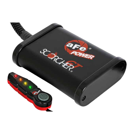
- Page 11 • Green LED: Stock • Yellow LED: Sport • Orange LED: Sport+ • Red LED: Race Use the grey button to select the desired setting. Power adjustments can be done at any moment. Thank you for choosing aFe POWER! Page 11 aFepower.com...
- Page 12 ® Page left blank intentionally Page 12...
- Page 13 Page left blank intentionally Page 13 aFepower.com...
- Page 14 ® Cat-Back Dual Exhaust Exhaust Y-Pipe OE Replacement Air Filter Cold Air Intake System System P/N: 48-43012 (Street) P/N: 51-22972-B (PDS) P/N: 49-43070-B (Blk Tip) P/N: 30-10162 (P5R) 48-43011 (Race) 54-22972-B (P5R) 49-43070-P (Pol Tip) 31-10162 (PDS) Oil Filter Rear Differential Cover Oil Cap Cat-Back Exhaust System P/N: 44-LF025...
-
Page 15: Warranty
Warranty General Terms: • aFe warrants their products to be free from manufacturer’s defects due to workmanship and material. • This warranty applies only to the original purchaser of the product and is non-transferrable. • Proof of purchase of the aFe product is required for all warranty claims. •... - Page 16 ® advanced FLOW engineering, inc. 252 Granite Street Corona, CA 92879 TEL: 951.493.7100 TECH: 951.493.7134 E-Mail:Tech@aFepower.com P/N: 06-80892...
Need help?
Do you have a question about the 77-43025 and is the answer not in the manual?
Questions and answers