
Subscribe to Our Youtube Channel
Related Manuals for aFe Power advanced FLOW engineering


Summary of Contents for aFe Power advanced FLOW engineering
- Page 1 ® advanced FLOW engineering Instruction Manual P/N: 77-43018 Make: Ford Model: F-150 Year: 2011-2014 Engine: V6-3.5L (tt) EcoBoost...
- Page 2 ® • Please read the entire instruction manual before proceeding. • Ensure all components listed are present. • If you are missing any of the components, call customer support at 951-493-7100. • Ensure you have all necessary tools before proceeding. •...
- Page 3 aFepower.com Page 3...
- Page 4 Refer to Figure A for Step 1. Step 1: Before installing the aFe POWER Module you must place your vehicles ECU in sleep mode. In order to place your vehicles ECU in sleep mode you will need to do the following: -If the engine is cold, open the hood, close the doors, lock the car and wait 30 seconds.
- Page 5 REMOVAL TMAP Figure B Refer to Figure B for Steps 2-3. Step 2: Remove engine cover to gain access to the MAP sensor. Step 3: Locate the MAP and TMAP sensor. The MAP sensor is located on the back of the intake manifold towards the firewall.
- Page 6 ® INSTALL Figure C Refer to Figures C for Steps 4-5. Step 4: Locate and disconnect the MAP sensor connector, by pressing down on the locking tab of the connector, and sliding it out of the sensor. Step 5: Locate the MAP sensor jumper harness on the aFe module. This is the shorter harness. Plug the female connector of the module to the stock MAP sensor, then take the male connector of the module and connect to the female connector of the engine harness.
- Page 7 INSTALL Figure D Refer to Figure D for Step 6. Step 6: Check with the pictures to make sure the connectors are correctly connected. Note: Make sure connections are fully engaged. Usually, connectors make a snapping sound when fully engaged. aFepower.com Page 7...
- Page 8 ® INSTALL Figure E Refer to Figure E for Steps 7-8. Step 7: Locate and disconnect the TMAP sensor connector, by pressing down on the locking tab of the connector, and sliding it out of the sensor. Step 8: Locate the TMAP sensor jumper harness on the aFe module. This is the longer harness. Plug the female connector of the module into the stock TMAP sensor, then the male connector of the module into female connector of the engine harness.
- Page 9 INSTALL Figure F Refer to Figure F for Step 9. Step 9: Check with the pictures to make sure the connectors are correctly connected. Note: Make sure connections are fully engaged. Usually, connectors make a snapping sound when fully engaged. Page 9...
- Page 10 ® INSTALL Figure G Refer to Figure G for Steps 10-11. Step 10: Carefully route the switch cable behind steering wheel cover. Step 11: Mount the Switch on an open, flat surface. Page 10...
- Page 11 INSTALL Figure H Refer to Figure H for Step 12. Step 12: Route the switch cable through firewall and into the engine bay. Follow the main harness through the grommet into the firewall. Plug the end of the cable to the module harness. Page 11...
- Page 12 ® INSTALL Figure I Refer to Figure I for Steps 13-14. Step 13: Mount the module in a safe location, such as the recessed area on the inner fender, using the supplied Velcro strip. Then, secure the wires and module away from any extreme heat and moving parts, with the provided ties.
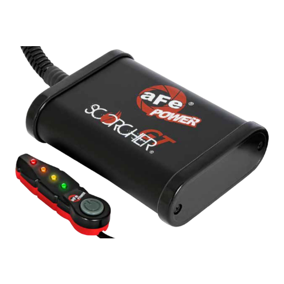
- Page 13 • Green LED: Stock • Yellow LED: Sport • Orange LED: Sport+ • Red LED: Race Use the grey button to select the desired setting. Power adjustments can be done at any moment. Thank you for choosing aFe POWER! Page 13...
- Page 14 ® OE Replacement Air Filter Air Intake System Side-Exit Exhaust System Cat-Back Exhaust System P/N: 30-10162 (P5R) P/N: 51-12182 (PDS) 2011 Only! P/N: 49-43078-B (Blk. Tips) P/N: 49-43067-B (Blk. Tip) 49-43078-P (Pol. Tips) 49-43067-P (Pol. Tip) 31-10162 (PDS) 54-12182 (P5R) 2011 Only! 51-12192 (PDS) ‘12-’14 Only! 54-12192 (P5R) ‘12-’14 Only! Sway-A-Way Front...
-
Page 15: Warranty
1 year No other warranty expressed or implied applies nor is any person or advanced FLOW engineering authorized to assume any other warranty. Some States do not allow the exclusion or limitation of incidental or consequential damages or do not allow limitations on how long an implied warranty lasts, so the above limitations or exclusions may not apply to you. - Page 16 ® advanced FLOW engineering, inc. 252 Granite Street Corona, CA 92879 TEL: 951.493.7100 TECH: 951.493.7134 E-Mail:Tech@aFepower.com P/N: 06-81073...
Need help?
Do you have a question about the advanced FLOW engineering and is the answer not in the manual?
Questions and answers