Advertisement
Quick Links
®
advanced FLOW engineering
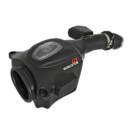
Momentum GT Cold Air Intake System
Instruction Manual
P/N: 51-76006 / 54-76006 / 75-76006
Make: Toyota Model: Land Cruiser (LC200/J200) Year: 2008-2019 Engine: V8-5.7L
Make: Toyota Model: Land Cruiser (LC200/J200) Year: 2012-2019 Engine: V8-4.6L
Make: Lexus Model: LX 570
Year: 2012-2019 Engine: V8-5.7L
Advertisement

Related Manuals for aFe Power Momentum GT


Summary of Contents for aFe Power Momentum GT
- Page 1 ® advanced FLOW engineering Momentum GT Cold Air Intake System Instruction Manual P/N: 51-76006 / 54-76006 / 75-76006 Make: Toyota Model: Land Cruiser (LC200/J200) Year: 2008-2019 Engine: V8-5.7L Make: Toyota Model: Land Cruiser (LC200/J200) Year: 2012-2019 Engine: V8-4.6L Make: Lexus Model: LX 570...
- Page 2 ® • Please read the entire instruction manual before proceeding. • Ensure all components listed are present. • If you are missing any of the components, call technical support at 951-493-7100 or e-mail tech@afepower.com. • Ensure you have all necessary tools before proceeding. •...
- Page 3 A1/A2/A3 aFepower.com Page 3...
- Page 4 ® REMOVAL Figure A Refer to Figure A for Step 1 Step 1: Lexus Only: Remove the 7 clips 1 holding down the side cover 2 by pushing down on the center of the clip to disengage them. Remove the side cover 2 . Page 4...
- Page 5 REMOVAL Figure B Refer to Figure B for Step 2 Step 2: Disconnect the MAF sensor 3 . Using a flat blade screwdriver, unclip the wire loom 4 from the air box. aFepower.com Page 5...
- Page 6 ® REMOVAL Figure C Refer to Figure C for Step 3 Step 3: Using a 10mm nut driver, loosen the clamp 5 at the air box. Unsnap the 4 clips 6 holding down the air box lid. Remove the lid and the air filter. Page 6...
- Page 7 REMOVAL Figure D Refer to Figure D for Step 4 Step 4: Using a 10mm nut driver, remove the 3 screws 7 holding the lower section of the air box. Remove the air box. aFepower.com Page 7...
- Page 8 ® REMOVAL Figure E Refer to Figure E for Step 5 Step 5: Using a 10mm nut driver, remove the 2 screws 8 and the air inlet 9 . Page 8...
- Page 9 REMOVAL Figure F Refer to Figure F for Step 6 Step 6: Remove the engine cover 10 by pulling up and then out. Set the engine cover aside. Page 9 aFepower.com...
- Page 10 ® REMOVAL Figure G Refer to Figure G for Step 7 Step 7: Remove the vacuum hose 11 and breather hose 12 from the intake tube. Page 10...
- Page 11 REMOVAL Figure H Refer to Figure H for Step 8 Step 8: Using a 10mm nut driver, loosen the clamp 13 at the throttle body and remove the intake tube. aFepower.com Page 11...
- Page 12 ® INSTALL Figure I Refer to Figure I for Step 9 Step 9: Remove the 3 screws with metal inserts and bushing 14 from lower section of the air box and install them into the aFe intake housing. Page 12...
- Page 13 INSTALL Figure J Refer to Figure J for Step 10 Step 10: Install the trim seal 15 on the inlet opening of the aFe housing. aFepower.com Page 13...
- Page 14 ® INSTALL Figure K Refer to Figure K for Step 11 Step 11: Install the aFe housing into the vehicle. Tighten the three mounting screws 16 with a 10mm socket and driver. Page 14...
- Page 15 INSTALL Figure L Refer to Figure L for Step 12 Step 12: Slide the aFe filter and clamp into the aFe housing and push it in until it locks into place. Do not tighten clamp at this time. aFepower.com Page 15...
- Page 16 ® INSTALL Figure M Refer to Figure M for Step 13 Step 13: Using a Phillips screw driver, remove the mass air flow sensor 17 from the upper half of the air box and install it on the aFe intake tube using the two supplied M4 screws and a Torx 20 driver. Page 16...
- Page 17 INSTALL Figure N Refer to Figure N for Step 14 Step 14: Using a 7/16" wrench, install the supplied brass fitting 18 into the aFe intake tube. aFepower.com Page 17...
- Page 18 ® INSTALL Figure O Refer to Figure O for Step 15 Step 15: Install the supplied silicone coupler 19 and clamp 20 onto the throttle body, snug but do not tighten the clamp. Place the T-bolt clamp 21 on the coupler, do not tighten at this time. Page 18...
- Page 19 INSTALL Figure P Refer to Figure P for Step 16 Step 16: Install the aFe intake tube into the coupler first and then into the filter. Tighten all the clamps. aFepower.com Page 19...
- Page 20 ® INSTALL Figure Q Refer to Figure Q for Step 17 Step 17: Connect the vacuum hose 22 and the breather hose 23 . Page 20...
- Page 21 INSTALL Figure R Refer to Figure R for Step 18 Step 18: Connect the MAF sensor 24 . aFepower.com Page 21...
- Page 22 ® INSTALL Figure S Refer to Figure S for Step 19 Step 19: Use the provided plug 25 to close additional air inlet if you want to completely seal the air box. Best performance gain is obtained by having more air flow (no plug). Page 22...
- Page 23 INSTALL Figure T Refer to Figure T for Step 20 Step 20: Install the engine cover. aFepower.com Page 23...
- Page 24 Refer to Figure U for Step 21 Step 21: Lexus Only: Install the side cover with all 7 clips. Thank you for Your installation is now complete. choosing aFe Power! NOTE: Check all bolts, clamps, and connectors after 100-200 miles. Page 24...
- Page 25 Page left blank intentionally Page 25...
- Page 26 ® Pro DRY S Air Filter Pro 10R Air Filter Pro-GUARD 7 Air Filter Pro DRY S Restore Kit P/N: 21-91092 P/N: 20-91092 P/N: 72-91092 P/N: 90-59999 aFe Motorsport T-Shirt Pre-Filter Blue Squeeze Restore Kit Gold Squeeze Restore Kit P/N: 40-30441-B (S) P/N: 28-10283 P/N: 90-50501 P/N: 90-50500...
-
Page 27: Warranty
Warranty General Terms: • aFe warrants their products to be free from manufacturer’s defects due to workmanship and material. • This warranty applies only to the original purchaser of the product and is non-transferrable. • Proof of purchase of the aFe product is required for all warranty claims. •... - Page 28 ® advanced FLOW engineering, inc. 252 Granite Street Corona, CA 92879 TEL: 951.493.7100 • TECH: 951.493.7134 E-Mail:Tech@aFepower.com P/N: 06-80896...
Need help?
Do you have a question about the Momentum GT and is the answer not in the manual?
Questions and answers