
Related Manuals for aFe Power 77-83028


Summary of Contents for aFe Power 77-83028
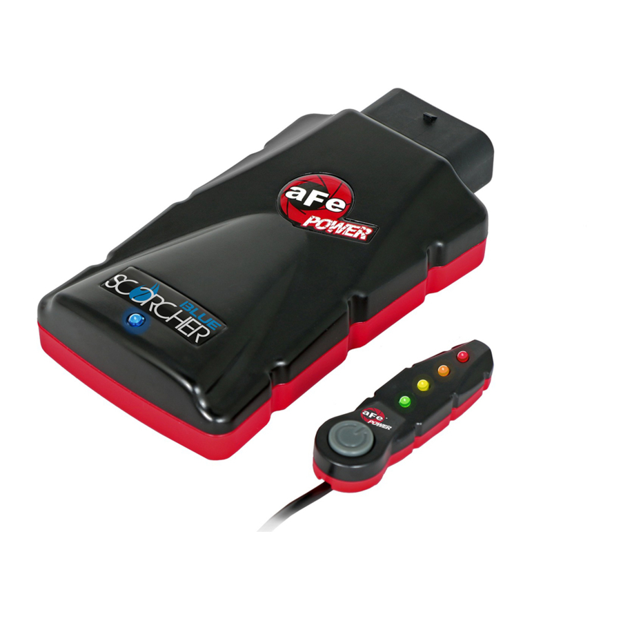
- Page 1 ® advanced FLOW engineering Instruction Manual P/N: 77-83028 Make: Ford Model: F-150 Year: 2018-2020 Engine: V6-3.0L (td) Power Stroke...
- Page 2 DISCLAIMER OF WARRANTY AND LIMITATION OF LIABILITY: Advanced FLOW Engineering, Inc (also known as aFe or aFe POWER) and its successors, distributors, jobbers, and dealers (hereafter “SELLER”) shall in no way be responsible for the product’s improper use and service.
- Page 3 Label Qty. Description Part Number Module R77-83028 LED Switch 05-70013 Bypass Plug 05-70017 Harness AFE-10-242 Velcro (2 Inches) 05-01244 Cable Ties 05-60167 Double Sided Tape 07-90001 aFepower.com Page 3...
- Page 4 Refer to Figure A for Step 1. Step 1: Before installing the aFe POWER Module you must place your vehicle’s ECU in sleep mode. In order to place your vehicles ECU in sleep mode you will need to do the following:...
- Page 5 REMOVAL FUEL PRESSURE Figure B Refer to Figure B for Steps 2-4. Step 2: Remove the engine cover and insulation foam to gain access to the MAP and Fuel Pressure sensors. Step 3: Locate the MAP sensor, it is on top of the intake manifold. Step 4: Locate the Fuel Pressure sensor, it is at the end of the fuel rail, to the left of the MAP sensor.
- Page 6 Step 6: Locate the section of the aFe POWER harness labeled “MAP.” Plug the female connector of the aFe POWER harness to the MAP sensor, then take the male connector of the aFe POWER harness and connect to the female connector of the engine harness.
- Page 7 INSTALL Figure D Refer to Figure D for Step 7. Step 7: Check with the picture to make sure the connectors are correctly connected. Make sure connections are fully engaged and not reversed. Usually, connectors make a snapping sound when fully engaged. aFepower.com Page 7...
- Page 8 Step 9: Locate the section of the aFe POWER harness labeled “Fuel”.” Plug the female connector of the aFe POWER harness into the fuel pressure sensor, then take the male connector of the module and connect to the female connector of the engine harness.
- Page 9 INSTALL Figure F Refer to Figure F for Step 10. Step 10: Check with the picture to make sure the connectors are correctly connected. Make sure connections are fully engaged and not reversed. Usually, connectors make a snapping sound when fully engaged. Page 9 aFepower.com...
- Page 10 13mm nut and placing the terminal and then reinstalling the nut. Step 12: Connect the red power terminal cable on the aFe POWER module to the positive battery post by removing the 10mm nut and placing the terminal and then reinstalling the nut.
- Page 11 INSTALL Figure H Refer to Figure H for Steps 13-14. Step 13: Secure the SCORCHER BLUE module on top of the battery, or any other desired location using the Velcro provided. The module must be located within reach of the LED switch cable if you are planning to use the switch.
- Page 12 ® INSTALL Figure I Refer to Figure I for Steps 15-16. Step 15: Select the desired location of the LED switch and route the cable through the top or bottom of the switch. Step 16: Use the provided double sided tape to secure the LED switch in the desired location. Page 12...
- Page 13 INSTALL Figure J Refer to Figure J Steps 17-18. Step 17: Carefully route the switch cable behind steering wheel cover or cabin trim cover. Step 18: Route the switch cable through firewall and into the engine bay. Follow the main harness through the grommet into the firewall.
- Page 14 ® INSTALL Figure K Refer to Figure K for Steps 19-21. Step 19: Plug the end of the switch cable to the harness inside the engine compartment. Step 20: Secure the wires away from any extreme heat and moving parts with the provided ties. Make sure all connections are secured and fully engaged.
- Page 15 Figure L Refer to Figure L. (Picture is for reference) The blue LED light will start flashing once the module is connected to the truck and the ECU on. The blue LED will become solid if the module gets connected through Bluetooth to a device. Page 15 aFepower.com...
- Page 16 ® Figure S Refer to Figure S (LED Switch). When turning on the vehicle, each LED will flash and it will stop at its last setting. The LED on the switch represents the different level of power. • Green LED: Stock •...
- Page 17 Figure T Refer to Figure T (app connection - iOS). For iOS device, download the app from the apps store. Make sure the Bluetooth is activated on your device. Open the app and it will automatically connect through Bluetooth to the SCORCHER BLUE module when the vehicle and module are on.
- Page 18 ® Figure U Refer to Figure U (app connection- Android). For Android device, download the app from the play store. For the first connection, go to the Bluetooth settings of your device, turn on Bluetooth and scan for available devices. Select “aFe SCOR” and pair with device.
- Page 19 Refer to Figure V (Custom Tuning). The aFe POWER SCORCHER BLUE app offers the capability to custom tune the different modes. Go to the menu on the top right corner and select “Tune”. Select the mode you would like to custom tune and adjust the sliders at low, medium and high load.
- Page 20 If you select a new mode it will reset and you can start again. If you need to stop the test at any point, hit the cancel button and leave the screen. Use the aFe POWER SCORCHER BLUE app responsibly. Always drive safely and obey traffic laws. aFe POWER is not responsible for any accidents, injuries, or property damage that may occur during its use.
- Page 21 Once the bypass plug is connected the vehicle will run in factory settings. Make sure the plug is fully engaged when connected to the harness. Thank you for choosing aFe POWER! The vehicle needs to be in sleep mode when the module gets disconnected and the bypass plug connected.
- Page 22 ® OE Replacement Air Filter Momentum HD Air Intake Intercooler Tubes Intercooler w/ Tubes P/N: 46-20364-B P/N: 30-10162 (P5R) P/N: 50-70023T (P10R) P/N: 46-20362-B 31-10162 (PDS) 50-70023D (PDS) Rebel Series DPF-Back Sprint Booster V3 DPF-Back Exhaust System Rear Differential Cover Exhaust P/N: 77-13001 P/N: 49-43106-B (Blk.
-
Page 23: Warranty
Warranty General Terms: • aFe warrants their products to be free from manufacturer’s defects due to workmanship and material. • This warranty applies only to the original purchaser of the product and is non-transferrable. • Proof of purchase of the aFe product is required for all warranty claims. •... - Page 24 ® advanced FLOW engineering, inc. 252 Granite Street Corona, CA 92879 TEL: 951.493.7100 • TECH: 951.493.7185 E-Mail:Tech@aFepower.com P/N: 06-81214...
Need help?
Do you have a question about the 77-83028 and is the answer not in the manual?
Questions and answers