Advertisement
Quick Links
advanced FLOW engineering
Instruction Manual
Make: Ford
Make: Ford
Make: Ford
Make: Lincoln
P/N: 77-43023
Model: F-150 Raptor
Model: F-150 Limited
Model: Expedition Platinum
Model: Navigator
Year: 2017-2020
Engine: V6-3.5L (tt) EcoBoost
Year: 2019-2020
Engine: V6-3.5L (tt) EcoBoost
Year: 2018-2020
Engine: V6-3.5L (tt) EcoBoost
Year: 2018-2020
Engine: V6-3.5L (tt) EcoBoost
Advertisement

Subscribe to Our Youtube Channel
Related Manuals for aFe Power 77-43023


Summary of Contents for aFe Power 77-43023
- Page 1 FLOW engineering Instruction Manual P/N: 77-43023 Make: Ford Model: F-150 Raptor Year: 2017-2020 Engine: V6-3.5L (tt) EcoBoost Make: Ford Model: F-150 Limited Year: 2019-2020 Engine: V6-3.5L (tt) EcoBoost Make: Ford Model: Expedition Platinum Year: 2018-2020 Engine: V6-3.5L (tt) EcoBoost...
- Page 2 • Please read the entire instruction manual before proceeding. • Ensure all components listed are present. • If you are missing any of the components, call customer support at 951-493-7100. • Ensure you have all necessary tools before proceeding. • Do not attempt to work on your vehicle when the engine is hot. •...
- Page 3 aFepower.com Page 3...
- Page 4 REMOVAL Figure A Refer to Figure A for Step 1. Step 1: Before installing your aFe module, you will have to place your vehicles ECU in sleep mode. In order to do this you will need to do the following: - If the engine is cold, open the hood, close the doors lock the car and wait 30 seconds.
- Page 5 REMOVAL Figure B Refer to Figure B for Steps 2-3. Step 2: Remove engine cover to gain access to the MAP sensor. Step 3: Locate the MAP and TMAP sensor. The MAP sensor is located on the back of the intake manifold towards the firewall.
- Page 6 INSTALL Figure C Refer to Figures C for Steps 4-5. Step 4: Locate and disconnect the MAP sensor. Step 5: Locate the MAP sensor jumper harness on the aFe module. This is the shorter harness. Plug the male connector of the module to the stock MAP sensor, then take the female connector of the module and connect to the male connector of the engine harness.
- Page 7 INSTALL Figure D Refer to Figure D for Steps 6-7. Step 6: Disconnect the MAP sensor. Step 7: Locate the TMAP sensor jumper harness on the aFe module. This is the longer harness. Plug the male connector of the module to the stock TMAP sensor, then the female connector of the module male connector of the engine harness.
- Page 8 INSTALL Figure E Refer to Figure E for Steps 8-9. Step 8: Carefully route the switch cable behind steering wheel cover. Step 9: Mount the Switch on an open, flat surface. Page 8...
- Page 9 INSTALL Figure F Refer to Figure F for Step 10. Step 10: Route the switch cable through firewall and into the engine bay. Follow the main harness through the grommet into the firewall. Plug the end of the cable to the module. Page 9 aFepower.com...
- Page 10 INSTALL Figure G Refer to Figure G for Steps 11-12. Step 11: Mount the module in a safe location, using the supplied Velcro strip. Then, secure the wires and module away from any extreme heat and moving parts, with the provided ties. Make sure all connections are secured and fully engaged.
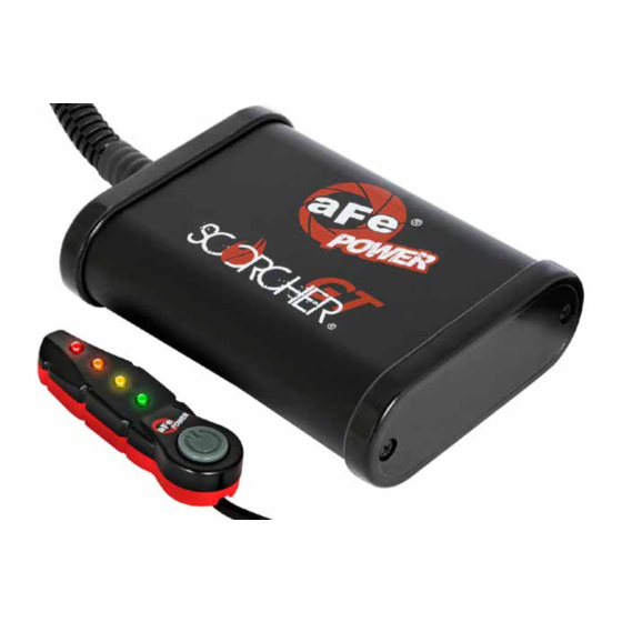
- Page 11 • Green LED: Stock • Yellow LED: Sport • Orange LED: Sport+ • Red LED: Race Use the grey button to select the desired setting. Power adjustments can be done at any moment. Thank you for choosing aFe POWER! Page 11 aFepower.com...
- Page 12 Page left blank intentionally Page 12...
- Page 13 Page left blank intentionally Page 13 aFepower.com...
- Page 14 Cat-Back Exhaust System Rear Differential Cover OE Replacement Air Filter Air Intake System P/N: 49-43045-B (Blk Tip) P/N: 30-10162 (P5R) P/N: 51-73115 (PDS) P/N: 46-70152-WL (w/ Oil) 49-43045-P (Pol Tip) 31-10162 (PDS) 54-73115 (P5R) 46-70152 (Blk) 46-70150 (RAW) Cat-Back Side-Exit Sprint Booster V3 Intercooler w/ Tubes Turbo Downpipes...
-
Page 15: Warranty
Warranty General Terms: • aFe warrants their products to be free from manufacturer’s defects due to workmanship and material. • This warranty applies only to the original purchaser of the product and is non-transferrable. • Proof of purchase of the aFe product is required for all warranty claims. •... - Page 16 advanced FLOW engineering, inc. 252 Granite Street Corona, CA 92879 TEL: 951.493.7100 TECH: 951.493.7134 E-Mail:Tech@aFepower.com P/N: 06-80919...
- Page 17 ® advanced FLOW engineering Instruction Manual P/N: 51-73115 / 54-73115 / 75-73115 Make: Ford Model: F-150 Raptor Year: 2017-2020 Engine: V6-3.5L (tt) EcoBoost Make: Ford Model: F-150 Year: 2017-2020 Engine: V6-3.5L (tt) EcoBoost Make: Ford Model: F-150 Year: 2018-2020 Engine: V6-2.7L (tt) EcoBoost...
- Page 18 ® • Please read the entire instruction manual before proceeding. • Ensure all components listed are present. • If you are missing any of the components, call customer support at 951-493-7185. • Ensure you have all necessary tools before proceeding. •...
- Page 19 A1/A2/A3 aFepower.com Page 3...
- Page 20 ® REMOVAL Figure A Refer to Figure A for Steps 1-2 Step 1: Unplug temp sensor harness 1 from the back side of the intake tube. Unclip the coolant line from the intake tube. Step 2: Loosen the clamps 2 on the intake tubes. Unclip the top of the air box 3 and remove the tube, air filter and top of the air box from the vehicle.
- Page 21 REMOVAL Refer to Figure B for Steps 3-5 Step 3: Unclip the wire from the back of the air box. Step 4: Remove the wastegate accuator from the housing. Step 5: Remove the screw 4 and the two plastic rivets 5 securing the housing, then pull the factory air box out of the truck.
- Page 22 ® REMOVAL Vent insert installation: Figure C Refer to Figure C for Step 6 (These procedures should be done with the inlet tubes installed on the engine. It is shown off the vehicle for better illustration.) Step 6: Locate the o.e. plastic tube feeding the driver’s side turbo inlet. Page 6...
- Page 23 REMOVAL Figure D Refer to Figure I for Step 7 Step 7: Locate the valve cover vent tube that feeds into driver’s side turbo inlet. It is not necessary to remove the engine cover. aFepower.com Page 7...
- Page 24 ® REMOVAL Figure E Refer to Figure E for Step 8 Step 8: Note the release clip on the vent tube connectors. Apply pressure against the exposed tail and pull vent fitting off of the turbo inlet tube. It is not necessary to disconnect at the valve cover end.
- Page 25 INSTALL Figure F Refer to Figure F for Step 9 Step 9: Insert vent fitting with slash cut facing turbo inlet. It should not be a loose fit. It is direction dependent and must not rotate once installed. aFepower.com Page 9...
- Page 26 ® INSTALL INSTALL Figure G Refer to Figure G for Steps 10-11 Step 10: Reconnect the vent fitting. It will snap over without having to release the plastic clip. Pull up slightly to confirm installation. Step 11: Installation is complete. Any codes can be cleared with a code reader or by disconnecting the battery.
- Page 27 INSTALL Figure H Refer to Figure H for Steps 12-13 Step 12: Transfer the grommet 6 from the factory air box to the aFe air box. Step 13: Install the furnished seal trim 7 on the top edge of the aFe housing. Optional: Drill two small holes in the top of the housing for the wastegate accutator wire harness to clip into.
- Page 28 ® INSTALL Figure I Refer to Figure I for Steps 14-17 Step 14: Install the aFe housing into the truck by pushing it into the factory mounting grommets. Step 15: Re-install the factory screw 9 removed in Step 5, inside the aFe housing. Step 16: Secure the housing with the two furnished plastic rivets 10 .
- Page 29 INSTALL Figure J Refer to Figure J for Step 18 Step 18: Slide aFe filter inside the housing and push it in until it locks. aFepower.com Page 13...
- Page 30 ® INSTALL Figure K Refer to Figure K for Steps 19-21 Step 19: Install grommet into hole in aFe tube then push the aluminum fitting in it. Step 20: Install couplings and clamps onto tube ends. Do not tighten clamps yet. Step 21: Transfer the temperature sensor from the factory intake tube to the new aFe intake tube.
- Page 31 INSTALL Optional Figure L Refer to Figure L for Steps 22-24 Step 22: Install the aFe tube in the truck by sliding the couplings over the factory tube then the tube end into aFe filter. Step 23: Align tube correctly then tighten all clamps. Step 24: Reconnect the temp sensor harness.
- Page 32 ® INSTALL Figure M Refer to Figure M for Step 25 Step 25: Make sure all clamps and screws are tight. Remove plastic film from aFe window. Your installation is now complete. NOTE: Check all bolts, clamps, and connectors after 200 miles. Page 16...
- Page 33 Page left blank intentionally Page 17...
- Page 34 49-43045-P (Pol. Tips) 49-43091-P (Pol. Tips) 46-70152 (Black) 46-70150 (RAW) Intercooler Cold-Side Tube SCORCHER GT Module P/N: 46-20299-B P/N: 77-43023 To purchase any of the items above, view airflow charts, dyno graphs, photos, and video; please go to aFepower.com. Page 18...
- Page 35 Warranty General Terms: • aFe warrants their products to be free from manufacturer’s defects due to workmanship and material. • This warranty applies only to the original purchaser of the product and is nontransferable. • Proof of purchase of the aFe product is required for all warranty claims. •...
- Page 36 ® advanced FLOW engineering, inc. 252 Granite Street Corona, CA 92879 TEL: 951.493.7100 • TECH: 951.493.7185 E-Mail:Tech@aFepower.com P/N: 06-80953...
Need help?
Do you have a question about the 77-43023 and is the answer not in the manual?
Questions and answers