
Subscribe to Our Youtube Channel
Related Manuals for aFe Power SCORCHER 77-44008


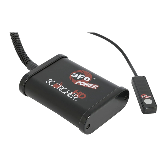
Summary of Contents for aFe Power SCORCHER 77-44008
- Page 1 advanced FLOW engineering Instruction Manual P/N: 77-44008 SCORCHER HD Module Make: GM Model: Silverado HD/Sierra HD Year: 2015-2016 Engine: V8-6.6L (td)
- Page 2 • Please read the entire instruction manual before proceeding. • Ensure all components listed are present. • If you are missing any of the components, call customer support at 951-493-7100. • Ensure you have all necessary tools before proceeding. • Do not attempt to work on your vehicle when the engine is hot. •...
- Page 3 aFepower.com Page 3...
- Page 4 REMOVAL Figure A Refer to Figure A for Steps 1-2. Step 1: Locate the MAP sensor 1 . The MAP sensor is next to the intake manifold Step 2: Locate the fuel pressure sensor 2 . It is accessible between the firewall and boost tube. Page 4...
- Page 5 INSTALL Figure B Refer to Figure B for Steps 3-4. Step 3: Disconnect the MAP sensor. Step 4: Locate the MAP sensor jumper harness on the aFe module. This is the longer harness with a red cable on both connectors. Plug the male connector of the module to the female connector of the engine harness, then the female connector of the module to the stock map sensor of the engine.
- Page 6 INSTALL Figure C Refer to Figures C for Steps 5-6. Step 5: Locate and disconnect the fuel pressure sensor, on the driver’s side of the engine . Step 6: Locate the fuel pressure sensor jumper harness on the aFe module. This is the shorter harness with a grey cable on both connectors.
- Page 7 INSTALL Figure D Refer to Figure D for Step 7. Step 7: Carefully detach the cover below the steering wheel to allow the switch and cable through 3 . Mount the Switch on an open, flat surface 4 . Route the switch harness and re-attach cover below steering wheel.
- Page 8 INSTALL Figure E Refer to Figure E for Step 8. Step 8: Route the switch cable through firewall and into the engine bay. Follow the main harness through the grommet into the firewall. Plug the end of the cable to the module. Page 8...
- Page 9 INSTALL Page left blank intentionally Figure F Refer to Figure F for Step 9. Step 9: Mount the module in a safe location, using the supplied Velcro strip. Then, secure the wires and module away from any extreme heat and moving parts, with the provided ties. Make sure all connections are secured and fully engaged.
- Page 10 Use the grey button to select the desired setting. Power adjustments can be done at any moment. Thank you for choosing aFe POWER! NOTE: Place enclosed CARB EO sticker on or near the device on a smooth, clean surface. EO identification label is required to pass the smog test inspection.
- Page 11 Page left blank intentionally aFepower.com Page 11...
- Page 12 Page left blank intentionally Page 12...
- Page 13 Page left blank intentionally Page 13 aFepower.com...
- Page 14 Intercooler w/ Tubes Rear Differential Cover Transmission Pan Cover Air Intake System P/N: 46-20112 P/N: 46-70012-WL (w/ Oil) P/N: 46-70072 (Blk) P/N: 51-82322 (PDS) 46-700012 (Blk) 46-70070 (RAW) 75-82322 (PG7) 46-70010 (RAW) Air Intake System Sprint Booster Exhaust System Transmission Filter P/N: 50-74006-1 (P10R) P/N: 77-14003 P/N: 49-04044-P (Pol)
-
Page 15: Warranty
Warranty General Terms: • aFe warrants their products to be free from manufacturer’s defects due to workmanship and material. • This warranty applies only to the original purchaser of the product and is non-transferrable. • Proof of purchase of the aFe product is required for all warranty claims. •... - Page 16 advanced FLOW engineering, inc. 252 Granite Street Corona, CA 92879 TEL: 951.493.7100 E-Mail:Tech@aFepower.com P/N: 06-80820...
Need help?
Do you have a question about the SCORCHER 77-44008 and is the answer not in the manual?
Questions and answers