Advertisement
Quick Links
Instruction Manual
Make: BMW
Model: 330i/ix (F3X)
Make: BMW
Model: 340i/ix/GT (F3X)
Make: BMW
Model: 430i/ix/Gran Coupe (F3X)
Make: BMW
Model: 440i/ix/Gran Coupe (F3X)
Make: BMW
Model: 220i/ix 230i/ix (F2X)
Make: BMW
Model: M240i/ix (F2X)
Make: BMW
Model: M340i/ix (G20)
Make: BMW
Model: X3 (G01)
Make: BMW
Model: X3 (G01)
P/N: 77-86318
___
Year: 2016-2019
Year: 2016-2019
Year: 2017-2020
Year: 2016-2020
Year: 2017-2020
Year: 2016-2020
Year: 2020
Year: 2018-2021
Year: 2018-2021
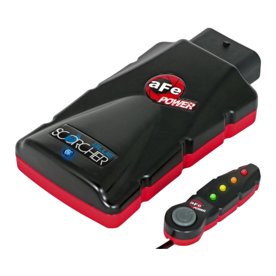
SCORCHER BLUE POWER MODULE
Engine: L4-2.0L (t) B48
Engine: L6-3.0L (t) B58
Engine: L4-2.0L (t) B48
Engine: L6-3.0L (t) B58
Engine: L4-2.0L (t) B46/B48
Engine: L6-3.0L(t) B58
Engine: L6-3.0L(t) B58
Engine: L4-2.0L (t) B48
Engine: L6-3.0L (t) B58
Advertisement

Subscribe to Our Youtube Channel
Related Manuals for aFe Power 77-86318


Summary of Contents for aFe Power 77-86318
- Page 1 Instruction Manual P/N: 77-86318 SCORCHER BLUE POWER MODULE Make: BMW Model: 330i/ix (F3X) Year: 2016-2019 Engine: L4-2.0L (t) B48 Make: BMW Model: 340i/ix/GT (F3X) Year: 2016-2019 Engine: L6-3.0L (t) B58 Make: BMW Model: 430i/ix/Gran Coupe (F3X) Year: 2017-2020 Engine: L4-2.0L (t) B48...
- Page 2 Label Qty. Description Part Number Module R77-86318 LED Switch 05-70029 Bypass Plug 05-70017 Harness AFE-10-208 Velcro (2” Inches) 05-01244 Cable Ties 05-60167 Double Sided Tape 07-90001 Page 3...
- Page 3 Figure A Refer to Figure A for Step 1 Step 1: Before installing your aFe POWER module, you will have to place your vehicle’s ECU in sleep mode. In order to do this, you will need to do the following: •...
-
Page 4: T-Map Sensor
REMOVAL MAP Sensor T-MAP Sensor Figure B Refer to Figure B for Steps 2-3 Step 2: Remove engine cover to gain access to the MAP and T-MAP sensors. Step 3: Locate the MAP and T-MAP sensors. MAP sensor is located on top of the intake manifold in proximity to the oil cap. - Page 5 Step 5: Locate the MAP sensor jumper harness on the aFe POWER harness. It is identified with a white label. Plug the female connector of the aFe POWER harness into the MAP sensor, then take the male connector of the aFe POWER harness and connect to the female connector of the engine harness.
- Page 6 INSTALL Figure D Refer to Figure D for Step 6 Step 6: Check with Figure D to make sure the connectors are correctly connected. Make sure that the connections are fully engaged. Usually, connectors make a snapping sound when fully engaged. Page 7...
- Page 7 Step 8: Locate the T-MAP sensor jumper harness on the aFe POWER harness. It is labeled T-MAP. This is the harness with four wires in each connector. Plug the female connector of the aFe POWER harness into the T-MAP sensor, then the male connector of the aFe POWER harness into the female connector of the engine harness.
- Page 8 INSTALL Figure F Refer to Figure F for Step 9 Step 9: Check with the pictures to make sure the connectors are correctly connected. Make sure that the connections are fully engaged. Usually, connectors make a snapping sound when fully engaged. Page 9...
- Page 9 For this installation, we chose to secure the Scorcher Blue module on top of the plastic cover near the strut tower on the driver side. Step 11: Connect the aFe POWER harness to the Scorcher Blue Module. Use the provided cable ties to secure the harness away from heat and moving parts.
- Page 10 INSTALL Figure H Refer to Figure H for Steps 13-15 (Optional) Step 13: Find the desired location for the LED switch. Step 14: Carefully route the switch cable behind steering wheel cover. Step 15: Mount the switch on an open, flat surface using the included double sided tape. Note: Installation of the LED switch is optional if using the Bluetooth app.
- Page 11 INSTALL Figure I Refer to Figure I for Step 16 (Optional) Step 16: Locate the hole behind the firewall leading into the driver side footwell. Route the cable from the LED switch from the cabin to the engine compartment. Page 12...
- Page 12 INSTALL Figure J Refer to Figure J for Steps 17-19 (Optional) Step 17: Remove the plastic cover by turning knob counter-clockwise to gain access to wire-routing slot in the firewall. Step 18: Connect the harness from the LED switch to the Scorcher module. Step 19: Reinstall the plastic cover on the driver side and turn the knob clockwise to lock it into place.
- Page 13 Figure K Refer to Figure K (Picture is for reference) The blue LED light will start flashing once the module is connected to the truck and the ECU is on. The blue LED will become solid if the module gets connected through Bluetooth to a device Page 14...
- Page 14 Figure L Refer to Figure L (LED Switch) When turning on the vehicle, each LED will flash, and it will stop at its last setting. The LED on the switch represents the different level of power. • Green LED: Stock •...
- Page 15 Figure M Refer to Figure M* (app connection-iOS) For iOS devices, download the app from the apps store. Make sure the Bluetooth is activated on your device. Open the app and it will automatically connect through Bluetooth to the SCORCHER BLUE module when both the vehicle and module are on. When connected, the vehicle description will appear on top of the screen and the gauges will show current data.
- Page 16 Figure N Refer to Figure N* (app connection-Android) For Android devices, download the app from the play store. For the initial connection, go to the Bluetooth settings of your device, turn on Bluetooth and scan for available devices. Select “aFe SCOR” and pair with device. The vehicle needs to be on and the module connected.
- Page 17 Figure O Refer to Figure O (Custom Tuning) The aFe POWER SCORCHER BLUE app offers the capability to custom tune the different modes. Go to the menu on the top right corner and select “Tune”. Select the mode you would like to custom tune and adjust the sliders at low, medium, and high load.
- Page 18 Use the aFe POWER SCORCHER BLUE app responsibly. Always drive safely and obey traffic laws. aFe POWER is not responsible for any accidents, injuries, or property damage that may occur during its use.
- Page 19 Figure Q Refer to Figure Q (Bypass Plug) A bypass plug is included in the kit. The plug can be connected to the harness instead of the module. Once the bypass plug is connected, the vehicle will run in factory settings. Make sure the plug is fully engaged when connected to the harness.
- Page 20 252 Granite Street Corona, CA 92879 P/N: 06-81421...
Need help?
Do you have a question about the 77-86318 and is the answer not in the manual?
Questions and answers