Advertisement
Quick Links
advanced FLOW engineering
Instruction Manual
Make: BMW Model: 125i/220i/ix/228i/ix (F2X)
Make: BMW Model: 328i/ix/GT/420i/ix/428i/ix (F3X)
Make: BMW Model: 430i/ix/GT (F3X)
Make: BMW Model: 528i/ix/Li/Lix (F1X)
Make: BMW Model: X1 28i/ix/X3 28i/ix/X4 28ix (E84/F2X)
Make: BMW Model: Z4 28i (E89)
P/N: 77-46316
®
Year: 2012-2016 Engine: L4-2.0L (t) N20
Year: 2012-2016 Engine: L4-2.0L (t) N20
Year: 2017-2020 Engine: L4-2.0L (t) N20
Year: 2010-2017 Engine: L4-2.0L (t) N20
Year: 2012-2018 Engine: L4-2.0L (t) N20
Year: 2011-2016 Engine: L4-2.0L (t) N20
Advertisement

Related Manuals for aFe Power 77-46316


Summary of Contents for aFe Power 77-46316
- Page 1 ® advanced FLOW engineering Instruction Manual P/N: 77-46316 Make: BMW Model: 125i/220i/ix/228i/ix (F2X) Year: 2012-2016 Engine: L4-2.0L (t) N20 Make: BMW Model: 328i/ix/GT/420i/ix/428i/ix (F3X) Year: 2012-2016 Engine: L4-2.0L (t) N20 Make: BMW Model: 430i/ix/GT (F3X) Year: 2017-2020 Engine: L4-2.0L (t) N20 Make: BMW Model: 528i/ix/Li/Lix (F1X) Year: 2010-2017 Engine: L4-2.0L (t) N20...
- Page 2 ® • Please read the entire instruction manual before proceeding. • Ensure all components listed are present. • If you are missing any of the components, call customer support at 951-493-7185. • Ensure you have all necessary tools before proceeding. •...
- Page 3 aFepower.com Page 3...
- Page 4 ® REMOVAL Figure A Refer to Figure A for Step 1. Step 1: Before installing your aFe module, you will have to place your vehicles ECU in sleep mode. In order to do this you will need to do the following: - If the engine is cold, open the hood, close the doors lock the car and wait 30 seconds.
- Page 5 REMOVAL Figure B Refer to Figure B for Step 2. Step 2: Locate the TMAP 1 and MAP sensors 2 . The MAP sensor is located on top of the intake manifold under the engine cover, the TMAP sensor is located on the charge pipe, just before the throttle body.
- Page 6 ® INSTALL Figure C Refer to Figure C for Steps 3-4. Step 3: Remove the engine cover to gain access to the MAP sensor then disconnect the MAP sensor. Step 4: Locate the MAP sensor jumper harness on the aFe module. This is the shortest harness with three wires on each connector.
- Page 7 INSTALL Figure D Refer to Figures D for Steps 5-6. Step 4: Locate and disconnect the TMAP sensor. Step 5: Locate the TMAP sensor jumper harness on the aFe Module. This is the longer harness with four wires on each connector. Plug the male connector of the module to the stock TMAP sensor, then take the female connector of the module and connect to the male connector of the engine harness.
- Page 8 ® INSTALL Figure E Refer to Figure E for Steps 7-8. Step 7: Carefully route the switch cable behind steering wheel cover. Step 8: Mount the Switch where desired on an open, flat surface. Page 8...
- Page 9 REMOVAL Figure F Refer to Figure F for Steps 9-11. Step 9: Remove the two 10mm nuts holding the foot trim panel. Step 10: Route the switch cable through firewall and into the engine bay. Follow the main harness through the grommet into the firewall. Plug the end of the cable to the module. Step 11: Re-install foot trim panel.
- Page 10 ® INSTALL Figure G Refer to Figure G for Step 12. Step 12: Mount the module in a safe location with adequate hood clearance, using the supplied Velcro strip. Then, secure the wires and module away from any extreme heat and moving parts, with the provided ties.
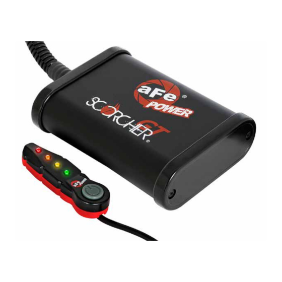
- Page 11 • Green LED: Stock • Yellow LED: Sport • Orange LED: Sport+ • Red LED: Race Use the grey button to select the desired setting. Power adjustments can be done at any moment. Thank you for choosing aFe POWER! Page 11...
- Page 12 ® advanced FLOW engineering, inc. 252 Granite Street Corona, CA 92879 TEL: 951.493.7100 TECH: 951.493-7185 E-Mail:Tech@aFepower.com P/N: 06-80934...
Need help?
Do you have a question about the 77-46316 and is the answer not in the manual?
Questions and answers