Table of Contents
Advertisement
Quick Links
Advertisement
Table of Contents

Related Manuals for Chore-Time H2


Summary of Contents for Chore-Time H2
- Page 1 MODEL H2™ Feeding System Installation and Operators Manual July 2023 MF830E...
-
Page 2: Chore-Time Warranty
If such a defect is found by Chore-Time to exist within the one-year period, Chore-Time will, at its option, (a) repair or replace such product free of charge, F.O.B. the factory of manufacture, or (b) refund to the original purchaser the original purchase price, in lieu of such repair or replacement. - Page 3 Warranty. Chore-Time shall not be liable for any consequential or special damage which any purchaser may suffer or claim to suffer as a result of any defect in the product. “Consequential” or special damages” as used herein include, but are not limited to, lost or damaged products or goods, costs of transportation, lost sales, lost orders, lost income, increased overhead, labor and incidental costs and operational inefficiencies.
-
Page 4: Table Of Contents
Chore-Time Warranty ........ - Page 5 Model H2 Mid-Line Control-Single Phase: 25435........
-
Page 6: About This Manual
About This Manual MODEL H2™ Feeding System About This Manual The intent of this manual is to help you in two ways. One is to follow step-by-step in the order of assembly of your product. The other way is for easy reference if you have questions in a particular area. -
Page 7: Safety Instructions
MODEL H2™ Feeding System Safety Instructions Safety Instructions Follow Safety Instructions Carefully read all safety messages in this manual and on your equipment safety signs. Follow recommended precautions and safe operating practices. Keep safety signs in good condition. Replace missing or damaged safety signs. -
Page 8: General
8 weeks. The H2 Feeders with Feed Windows are specifically designed to fill the feeder pan with feed while the birds are very young. This insures the birds know where to get feed and have easy access to it. - Page 9 The windows in the feeders may be closed to reduce the amount of feed into the feeder pan. The H2 Feeder Pans have the ability to swing down to facilitate wasy cleaning without needing to fully remove the feeder pans see figure 4.
-
Page 10: Manufacturer's Recommendations: Birds Per Pan
* NOTICE: The above Manufacturer’s recommendations do not constitute a product warranty and are in no way to be considered as a guarantee of performance for poultry production. In addition, the above information in no way alters or revises the terms and conditions of any applicable Chore-Time manufacturer’s warranty. -
Page 11: Glossary Of Terms
MODEL H2™ Feeding System Glossary of Terms Glossary of Terms Mid-Line control: End control: A feeder, equipped A feeder, equipped with a with a switch, (located switch, (located at the near the center of the power unit) used to control feeder line) used to the feeding system. -
Page 12: Planning The Floor Feeding System
Planning the Floor Feeding System MODEL H2™ Feeding System Planning the Floor Feeding System 1. Select the House Layout. 10' [3 m] 10' [3 m] Minimum Minimum 2) Brood Curtain 1) Control Tube 1) Control Tube 3) Feed Hopper 4) Mid Line Control... -
Page 13: General Installation Information
This rating is based on feed with a density of 40 pounds per cubic foot or 640 kg per cubic meter. Single phase 60 Hz and single and three phase 50 Hz Power Units are available for the Model H2 Feeders. -
Page 14: Suspension System
Suspension System MODEL H2™ Feeding System B. For systems over 350' [107 m] Figure 9. Suspension for systems over 350’ [107 m] 2. Locate the Power Lift Winch. The Power Lift Winch requires a support that will span, in a wood frame house at least 3 rafters, and in a steel frame house at least 2 rafters. -
Page 15: Installing The Main Winch Cable
MODEL H2™ Feeding System Suspension System with where the main cable is to be installed. Figure 12. Mounting the Power Lift Winch and Support to the Rafters Installing the Main Winch Cable The Suspension Systems are based on ceiling heights of 14' [4.3 m] with Suspension Drop points every 8' [2.4 m]. -
Page 16: Screw Hook Installation
Figure 16. Power Winch Drum Rotation Screw Hook Installation The recommended distance between the drops for the Model H2 is 8’ [2.4 m] on center. Do not exceed 10’ [3 m] spacing on drop lines. If the distance raised is greater than the distance between the drop spacings, offset the hooks 3"... -
Page 17: Ceiling Hook Installation
MODEL H2™ Feeding System Suspension System Ceiling Hook Installation Item Description Part No. Ceiling Hook 28550 Steel Truss Wood Truss 1/4-20 Lag Screw Cable Travel Direction Weld Figure 19. Pulley Installation 6. After securing the Ceiling Hook to the truss, slide the... -
Page 18: Hopper Assembly Procedure
Loosely, assemble the 200# Hopper Side Panels, as shown in Figure 22, using 1/4-20 bolts and 1/4-20 hex nuts (supplied in Hardware Package). The Hopper should be assembled so that the "CHORE-TIME" decals are on opposite sides of the hopper. - Page 19 MODEL H2™ Feeding System Hopper Assembly Procedure K e y D e s c r i p t i o n C l e v is P in a n d H a i r P i n C a b l e A s s e m b l y...
-
Page 20: 100# Hopper
Hopper Assembly Procedure MODEL H2™ Feeding System 100# Hopper Loosely, assemble the 100# Hopper Side Panels, as shown in Figure 25, using 1/4-20 bolts and 1/4-20 hex nuts (supplied in Hardware Package). Assemble the Hopper Hangers, as shown in Figure 25. - Page 21 MODEL H2™ Feeding System Hopper Assembly Procedure Figure 26. 100# Hopper Suspension Components Suspend the hopper, as shown in Figure 13. on page 15 by routing the cable around the Full Line Suspension Pulley and fastened to the main cable, using (2) cable clamps.
-
Page 22: Feeder Line Assembly & Suspension
The Fingers of the Feed Chute must be pointed down, toward the feeder pan. Figure 1 - 3 on page 8 show the three different Versions of the Model H2 Feeder. 4. Build all the required Feeder Assemblies for the house. -
Page 23: Feeder Pan And Tube Assembly Process
The single strut of each feeder should be on the same side of the auger tube throughout the system. Additionally, if Chutes or Collars are to be used with the Model H2 Feeders, they must be installed at this time. Feed Chutes and Flood Colors must be installed as specified on page 22. - Page 24 • the Chore-Time logo is on crown of tube. • make sure the clamps are located, as shown in Figure 33. Finally, tighten the Tube Clamps on the feeder tubes. Clamp the joints securely, but do not crush the tubes.
-
Page 25: Installing The End Control, Boot Assembly, And Auger
MODEL H2™ Feeding System Installing the End Control, Boot Assembly, and Auger The End Control Unit must be at least 10 feet [3 m] from the end of the building to allow birds access around the end of the feeder line. - Page 26 MODEL H2™ Feeding System CAUTION KEEP HANDS AWAY FROM PINCH POINTS WHEN INSTALLING AUGER. 1. Use extreme caution when pushing the auger into the auger tubes. Keep your hand away form the end of the auger tube to avoid injury.
- Page 27 MODEL H2™ Feeding System 4. Slide the Drive Tube and flat washer over the output shaft on the Power Unit, as shown in Figure 39.. 5. Continue installing auger until the auger reaches the Control Unit end of the feeder line.
- Page 28 MODEL H2™ Feeding System 8. Install the Metal Water Tight Connector (item 1) in the Feed Line Motor (item 2). Cut the Flex Conduit (item 3) to length. Slide the wires from the end control through the Flex Conduit (item 3). Install the Flex Conduit (item 3) in the connectors.
- Page 29 MODEL H2™ Feeding System Use a hacksaw or bolt cutters to cut the auger at the stretched auger mark. 1) Locking Pliers 2) Use a hacksaw or bolt cutters to cut the auger 4) Boot under Feed Hopper 3) Pull an extra 8" [200 mm] of auger (minimum)
-
Page 30: Auger Brazing
MODEL H2™ Feeding System Auger Brazing The auger should be brazed if it is necessary to splice or lengthen it. A bronze, flux coated rod is recommended. The ends of the auger should butt against each other, DO NOT THREAD INSIDE EACH OTHER. See Figure 45. -
Page 31: Anti-Roost Installation
MODEL H2™ Feeding System Anti-Roost Installation 1. Unroll the bulk anti-roost cable. Note: If the cable is unrolled as shown in Figure 46, taking 5 loops of the coil with one hand, then changing hands to remove 5 loops as it is unrolled, it will lie flat during installation. - Page 32 MODEL H2™ Feeding System Spring Should be stretched Wire Form Clamp with Anti-Roost 3/4" to 1" [19mm to 25mm] Insulator Bracket and Insulator Clamp Figure 49. Anti-Roost Installation at the Control Unit 11. Install the Poultry Trainer or Line Charger, as shown in Figure 50 or 51.
- Page 33 MODEL H2™ Feeding System Figure 51. Line Charger Installation 12. The anti-roost system must be on a separate electrical circuit, allowing the system to be disconnected by a switch near the door. Remember, the anti-roost system should be grounded through the poultry trainer.
-
Page 34: Mid-Line Control
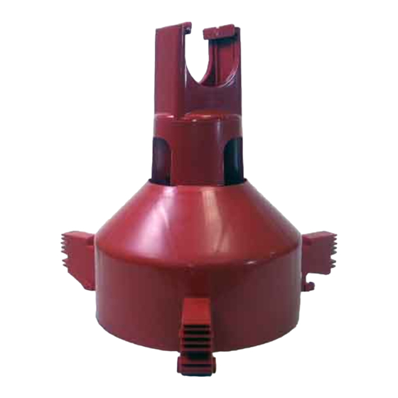
The Mid-Line Control makes it possible to operate the feeding system when birds are confined away from the End Control Unit. Chore-Time recommends placing the Mid-Line Control Feeder at least 2 pans away from the curtain or partition. See Figure 44. - Page 35 MODEL H2™ Feeding System Mid-Line Control 4. Install the Mid-Line Control: a. Remove the two hex head screws on the control top. b. Lift off the control top. c. Cradle the feeder tube in the control housing. The feeder tube may have to be turned slightly to allow the pan to hang straight.
-
Page 36: Meal-Time Feeding Guidelines
2. Model H2 Feeder: Set the Feed Windows in open or brood position to begin feeder operation 3. Adjust the feeder height weekly. At 3 weeks, the feeder should be high enough so that birds will not stand with one foot on pan lip but still will be able to reach feed. -
Page 37: Controlling The Feeders (Optional Equipment)
Controlling the Feeders (optional equipment) Controlling the Feeders (optional equipment) The Model H2 Feeding Systems may be controlled by the 34385 Control Panel or the 34574 Time Clock Control. Both controls use the Agri-Time Time Clock. Refer to the instructions shipped with each control for information on installation, wiring, programming, and operating the controls. -
Page 38: General Management & Start-Up
General Management & Start-Up MODEL H2™ Feeding System General Management & Start-Up This section provides you with valuable information concerning feeder operation and management. It is important that you read this information and understand how the feeding system was designed to operate. Once you become familiar with the system, you may custom operate it to fit your individual needs. -
Page 39: End Control And Mid Line Control Pans
MODEL H2™ Feeding System General Management & Start-Up The feeder tubes and auger are supplied from the factory with a protective oil coating that will cause the system to deliver feed at a reduced rate. The oil coating will also create a larger load on the power unit (motor) until the system has been initially purged with feed, and becomes broken in. -
Page 40: Feeders With Flood Collars
General Management & Start-Up MODEL H2™ Feeding System Feeder Management After birds are through the brood stage, the lip of the These recommendations are guidelines to aid producers in developing a pan should be at the feeding program. Many factors such as feed content, type of bird, etc. may approximate height the dictate change from these recommendations. -
Page 41: Maintenance
Maintenance Maintenance Floor Feeding System Maintenance The Model H2 Feeder requires minimum maintenance. However, a routine periodic inspection of the equipment will prevent unnecessary problems. Maintenance should be done by a qualified technician. ALWAYS DISCONNECT POWER TO THE SYSTEM WHEN SERVICING OR MAINTAINING THE EQUIPMENT. -
Page 42: Mechanical Switch Adjustment Procedure For Control Units
Maintenance MODEL H2™ Feeding System Mechanical Switch Adjustment procedure for Control Units A. Turn the adjustment nut counter-clockwise until the switch clicks. B. Turn the adjustment nut clockwise until the switch clicks. C. Turn the adjustment nut counter-clockwise 3/4 turn. -
Page 43: Power Lift Winch Maintenance
MODEL H2™ Feeding System Maintenance Power Lift Winch Maintenance Refer to Figure 61. Grease the winch every 6 months with 1 to 2 shots of common industrial or automotive grease. DO NOT OVER GREASE THE WINCH. 1)Grease the Power Lift Winch every 6 months with 1... -
Page 44: Trouble Shooting The Floor Feeding System
Trouble Shooting the Floor Feeding System MODEL H2™ Feeding System Trouble Shooting the Floor Feeding System ALWAYS DISCONNECT POWER TO THE SYSTEM WHEN SERVICING OR MAINTAINING THE EQUIPMENT. FAILURE TO DISCONNECT POWER MAY CAUSE INJURY OR DEATH. Service and maintenance work should be done by a qualified technician only. -
Page 45: Wiring
MODEL H2™ Feeding System Wiring Wiring End & Mid-Line Control Wiring Diagrams: Single Phase(ø) MF830E... -
Page 46: End & Mid-Line Control Wiring Diagrams: Three Phase(Ø)
Wiring MODEL H2™ Feeding System End & Mid-Line Control Wiring Diagrams: Three Phase(ø) MF830E... -
Page 47: Parts Listing
MODEL H2™ Feeding System Parts Listing Parts Listing 200# Hopper Components Item Description Part No. Hopper Cover Kit (optional) 28206 Cover Half (Removable) 28208 Cover Half (Stationary) 28207 Tube Support Assembly 14367 Clamp 13948 Chain 2128-0 Hopper Side (4 req’d) -
Page 48: Hopper Mount Bracket (Optional)
Parts Listing MODEL H2™ Feeding System Hopper Mount Bracket (Optional) Part Number 49358 - Hopper Suspension Kit Part No. Part No. Item Description Single Boot Twin Boot Clevis Pin, 5/16'' x 1'' 2797-1 2797-1 Adjustment Bracket 2706 2706 Hair Pin... -
Page 49: Twin Boot Components Part No. 6824
MODEL H2™ Feeding System Parts Listing Twin Boot Components Part No. 6824 Item Description Part No. Item Description Part No. Boot Weldment 3932 Setscrew 47867 Tube Clamp 24063 Anchor and Bearing Ass’y 39372 29373 Cannonball 3531 Outlet Tube 4556 Latch Pin Ass’y... -
Page 50: Feeder Line Components
Parts Listing MODEL H2™ Feeding System Feeder Line Components 1660-06 10/2000 Item Description Part No. 1/16'' Cable 1922 Charger Wire (165') 28994-165 Charger Wire (330') 28994-330 Spring 7551 1/16'' Cable Clamp 1826 Auger 6820-0 Tube Clamp 24063 Anti-Roost Bracket 24060... -
Page 51: Power Unit Assemblies
MODEL H2™ Feeding System Parts Listing Power Unit Assemblies Item Description 3259-8 3259-25 3259-84 3259-85 3259-98 3259-100 3259-128 Part No. Part No. Part No. Part No. Part No. Part No. Part No. Pinion Assembly 5046 5046 5046 5046 5046 5046... -
Page 52: Model H2 End Control-Single Phase: 24397
Parts Listing MODEL H2™ Feeding System Model H2 End Control-Single Phase: 24397 Model H2 End Control-Three Phase: 27762 1 Phase 3 Phase 1 Phase 2 Phase Item Description Part No. Part No. Item Description Part No. Part No. 24901 24901... -
Page 53: Model H2 Mid-Line Control-Single Phase: 25435
MODEL H2™ Feeding System Parts Listing Model H2 Mid-Line Control-Single Phase: 25435 Model H2 Mid-Line Control-3 Phase: 27760 1 Phase 3 Phase 1 Phase 3 Phase Item Description Part No. Part No. Item Description Part No. Part No. 24901 24901... -
Page 54: Winch (Part No. 47687)
Parts Listing MODEL H2™ Feeding System Winch (part no. 47687) Item Qty. Description Part No. Pawl 47687-5 Input Shaft Assembly 47687-1 Miscellaneous Suspension Components Item Description Part No. Item Description Part No. Standard Screw Hook 1214 3/32" Cable 4973 Large screw hook 2014 3/16"... -
Page 55: Model H2 Feeder Assemblies
24900-6 Flood Collar 25360 Support Cap 25052 Support Insert (swinging) 28356 Model H2 Cone (Slide Top, w/o Windows) 24900-3 Model H2 Cone (Slide Top, w/Windows) 24900-4 Model H2 1-Piece Feeder (w/o Windows) 27110 Model H2 1-Piece Feeder (w/Feeder Chute) 27115... - Page 56 Description of Change Was 2883 Winch 35577 Various Update Graphics For additional parts and information, contact your nearest Chore-Time distributor or representative. Find your nearest distributor at: www.choretime.com/contacts CTB, Inc. PO Box 2000 Milford, Indiana 46542-2000 USA Phone (574) 658-4101 Email: choretime@choretime.com...
Need help?
Do you have a question about the H2 and is the answer not in the manual?
Questions and answers