
Subscribe to Our Youtube Channel
Related Manuals for Teledyne Linea CL LA-CM-08K08A


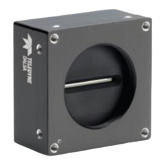
Summary of Contents for Teledyne Linea CL LA-CM-08K08A
- Page 1 ™ Linea Camera User’s Manual 2k, 4k, 8k and 16k Monochrome CMOS Line Scan sensors | cameras | frame grabbers | processors | software | vision solutions P/N: 03-032-20206-04 www.teledynedalsa.com...
- Page 2 All information provided in this manual is believed to be accurate and reliable. No responsibility is assumed by Teledyne DALSA for its use. Teledyne DALSA reserves the right to make changes to this information without notice. Reproduction of this manual in whole or in part, by any means, is prohibited without prior permission having been obtained from Teledyne DALSA.
-
Page 3: Table Of Contents
Contents LINEA™ CL SERIES OVERVIEW ..............4 ....................4 ESCRIPTION ..................5 AMERA IGHLIGHTS Key Features ..................5 Programmability ..................5 Applications ................... 5 ............6 UMBERS AND OFTWARE EQUIREMENTS ..............7 AMERA PECIFICATIONS VERVIEW Compliance, EMI Certifications ..............8 ............... 9 UPPORTED NDUSTRY TANDARDS... - Page 4 ....................38 INNING ) ............ 40 IXEL EADOUT IRECTION IRRORING (AOI) S ............... 41 REA OF NTEREST ETUP ............44 AVING AND ESTORING AMERA ETTINGS Camera Configuration Selection Dialog ............ 44 ................46 AMERA IRMWARE PDATES ............46 OWNLOAD A IST OF AMERA ARAMETERS...
- Page 5 Disabling the Esc Key for Direct Access to ASCII Commands ...... 68 ..................69 OMMAND EFERENCE APPENDIX C: ERROR AND WARNING MESSAGES ......... 81 ST: B ................81 UILT IN ................82 PERATIONAL RROR ODES APPENDIX D: CAMERA, FRAME GRABBER COMMUNICATION ....... 83 Setting Up Communication between the Camera and the Frame Grabber ..................
-
Page 6: Linea™ Cl Series Overview
Linea™ CL Series Overview Description Teledyne DALSA introduces a new CMOS camera family with the 2k, 4k, 8k, and 16k resolution Linea monochrome cameras. These new camera models use Teledyne DALSA's single line, 7.04 µm x 7.04 µm (2k, 4k, 8k) or 3.52 µm x 3.52 µm (16k) pixel array, delivering both speed and responsivity at a competitive price. -
Page 7: Camera Highlights
Camera Highlights Teledyne DALSA introduces a new CMOS camera family with the 2k, 4k, 8k, and 16k resolution Linea monochrome cameras. These new camera models use Teledyne DALSA's single line, 7.04 µm x 7.04 µm (2k, 4k, 8k) or 3.52 µm x 3.52 µm (16k) pixel array, delivering both speed and responsivity at a competitive price. -
Page 8: Part Numbers And Software Requirements
Part Numbers and Software Requirements This manual covers the Linea CL models summarized below. New models area added to this manual as they are released by Teledyne DALSA. Max. Line Rate Lens Mount Product Number Camera Resolution Pixel size (threaded) -
Page 9: Camera Specifications Overview
Camera Specifications Overview Specifications Performance Imager Format High speed CMOS line scan Resolution 2048, 4096, 8192, and 16,384 pixels Pixel Size 7.04 µm x 7.04 µm (2k, 4k, 8k) and 3.52 µm x 3.52 µm (16k) Pixel Fill Factor 100 % Line Rate Up to 80 kHz (2k, 4k, 8k) and up to 48 kHz (16k) Exposure Time... -
Page 10: Compliance, Emi Certifications
Front plate temperature: 45º C. Compliance, EMI Certifications For compliance and EMI certifications refer to the product page on the Teledyne DALSA website. For more information on FCC and CE compliance refer to the EMC Declarations of Conformity section. -
Page 11: Supported Industry Standards
Control Protocol (GenCP V1.0) to communicate over the Camera Link serial port. For more information see www.genicam.org. Teledyne DALSA recommends using Sapera CamExpert as your Camera Link compliant camera interface application. CamExpert is the camera interfacing tool supported by the Sapera library and comes bundled with SaperaLT. -
Page 12: Responsivity
Responsivity The responsivity graph describes the sensor response to different wavelengths of light (excluding lens and light source characteristics). 10 Linea™ CL Series Overview Linea CL Series Camera... -
Page 13: Effective Quantum Efficiency
Effective Quantum Efficiency The quantum efficiency graph describes the fraction of photons at each wavelength that contribute charge to the pixel. Linea CL Series Camera Linea™ CL Series Overview 11... -
Page 14: Linea Cl Camera Setup
Recommended System Requirements To achieve best system performance, the following minimum requirements are recommended: High bandwidth frame grabber. For example, Teledyne DALSA Xtium-CL series frame grabbers: http://www.teledynedalsa.com/imaging/products/fg/#digital-cameralink. Operating systems: Refer to frame grabber documentation for supported platforms. -
Page 15: Setup Steps: Overview
3. Establish communication with the camera Step 1: Install and Configure Frame Grabber and Software Teledyne DALSA recommends its Xtium-CL series frame grabbers or equivalent. Follow the manufacturer’s installation instructions. For additional information on configuring frame grabbers, see Appendix D: Camera, Frame Grabber Communication. - Page 16 The following figure of the Linea CL back end shows connector and LED locations. See the Mechanical Specifications section for details on the connectors and camera mounting dimensions. Power Hirose 6-pin +5V to +24V DC (2k and 4k) +12V to +24V DC (8k and 16k) Control &...
- Page 17 PoCL specification as their operation is dependent on the frame grabber used. These cameras exceed the 4 W PoCL power specification, but some frame grabbers, such as the Xtium frame grabber from Teledyne Dalsa, are able to supply sufficient power for the camera’s operation.
-
Page 18: Step 3: Establish Communication With The Camera
The camera is designed to power up with a GenICam-compliant interface. CamExpert provides an easy-to-use GUI that can be used to set up and operate the camera. The camera also comes with Teledyne DALSA’s three letter command (TLC) interface option, which can be accessed using a suitable terminal program such as HyperTerminal™. - Page 19 1. Start a new Sapera CamExpert application (or equivalent Camera Link compliant interface) by double clicking the desktop icon created during the software installation. 2. In CamExpert, for Teledyne DALSA frame grabbers, the camera appears below the Board category. Check LED Status If the camera is operating correctly at this point, the diagnostic LED is steady green.
-
Page 20: Using Camexpert With Linea Cl Cameras
Using CamExpert with Linea CL Cameras The Sapera CamExpert tool is the interfacing tool for GenCP compliant Camera Link cameras, and is supported by the Sapera library and hardware. When used with a Linea CL camera, CamExpert allows a user to test most of the operating modes. Additionally CamExpert saves the Linea CL user settings configuration to the camera or saves multiple configurations as individual camera parameter files on the host system (*.ccf). - Page 21 Device Selector pane: View and select from any installed Sapera acquisition device. After a device is selected, CamExpert will only present parameters applicable to that device. Optionally select a camera file included with the Sapera installation or saved by the user. ...
-
Page 22: Creating A Camera Configuration File In The Host
Visibility level from the View ∙ Parameters Options menu. Creating a Camera Configuration File in the Host When using the Teledyne DALSA Sapera SDK – the CCF is created automatically via a save. When using a 3 party SDK application, if that SDK supports GenAPI 2.4, then the process is... -
Page 23: Camera Operation
Camera Operation The following sections describe typical operations performed with the camera. The descriptions rely on the feature-based Camera Link GenCP protocol, using the Sapera CamExpert application. If you are using a different application, the display configuration will differ but the category, parameter (feature) names and possible values remain the same. -
Page 24: Typical Setup And Evaluation
Typical Setup and Evaluation Optical Configuration Typically, the first thing you want to do is to evaluate the camera’s image quality under operating conditions similar to those that you are likely to use in your application. To do this, take the following steps: ... -
Page 25: Check Camera And Sensor Information
Check Camera and Sensor Information Camera and sensor information can be retrieved via a controlling application—for example, the CamExpert GUI shown in the following examples. Parameters such as camera model, firmware version, sensor characteristics, and so forth, are read to uniquely identify the connected device. The parameters used to select, load and save user sets are grouped together under the Camera Information category. -
Page 26: Set Baud Rate
230400* 460800* Note: During connection, by default, CamExpert automatically sets the camera to maximum allowable baud. *A Teledyne DALSA PX4 or equivalent frame grabber is required to achieve these baud rates. Data Size 8 (read-only) Parity None (read-only) -
Page 27: Camera Link Configuration
Camera Link Configuration The following Camera Link configurations are available: Name Taps Bits Per Pixel Cables Base 8, 12 Medium 4 8, 12 Full Deca* *8k and 16k models only Available Camera Link speeds are model dependent: Camera Model Available Camera Link Speeds 2k, 4k, and 8k 77 MHz 50 MHz... -
Page 28: Pixel Format
Pixel Format Use the Pixel Format feature, found in the Image Format category, to select the format of the pixel to use during image acquisition as either Mono 8 or Mono 12 bit depth. Image Format Parameter Description Pixel Format Sets the sensor pixel format. - Page 29 Image is from the camera sensor. Ramp Image is filled horizontally with an image that goes from the darkest possible value to the brightest. Alternating Alternating values. For 12-bit output, pixel values alternate between 1381 (0x565) and 2746 (0xABA). For 8-bit output, pixel values alternate between 86 (0x56) and 172 (0xAC).
-
Page 30: Calibrating The Camera
Calibrating the Camera Important Note: to ensure best results, the conditions under which you calibrate the camera (for example, temperature and illumination) should be as close to the actual operating conditions as possible. The goal of calibration is for the camera to produce a uniform output image at a desired level while imaging a uniform white object under conditions equal to the optical setup for the user’s application. - Page 31 Once complete, remove the lens cap and perform a photo response non-uniformity (PRNU) calibration using the desired target value (in DN). You want all the pixels to match. This target value should be higher than the peak values you saw while first setting up the camera.
-
Page 32: Flat Field Parameters
Flat Field Parameters This Flat Field category contains a number of features that are used to correct image distortion due to lens vignetting and uneven illumination. Flat Field Parameter Description Mode Off – Flat field correction coefficients are not applied. On –... - Page 33 This feature may not be of use to many users as the camera already subtracts true “dark current”, but it may be useful for some to provide a per pixel offset correction. Range 0 to 511 DN (12-bit) or 0 to 31 DN (8-bit) ...
-
Page 34: Gain And Black Level (Offset)
Gain and Black Level (Offset) The gain and black level controls can make small compensations to the acquisition in situations where lighting varies and the lens iris cannot be easily adjusted. Optimal gain and black level adjustments maximizes the Linea CL dynamic range for individual imaging situations. Use the Offset and Gain features to maximize the use of the output dynamic range (especially when pixel format is less than 12-bits). - Page 35 The parameters that control gain and black level are grouped together in the Camera Control category. Camera Control Single value added to each pixel. Apply a digital addition after an FPN correction: ± Offset 1/8 of available range. Positive values may be used to measure dark noise. Depending on the the pixel format, different offset ranges are available: 12-bit mode available range is -512 to +511.
-
Page 36: Trigger Modes
Trigger Modes The camera’s image exposures are initiated by a trigger event. The trigger event is either a programmable internal signal used in free running mode, an external input used for synchronizing exposures to external triggers, or a programmed function call message by the controlling computer. -
Page 37: Exposure Controls
Exposure Controls Exposure control is defined as the start of exposure and exposure duration. Exposure control modes define the method and timing of controlling the sensor integration period. The integration period is the amount of time the sensor is exposed to incoming light before the video line data is transmitted to the controlling computer. - Page 38 Camera Control Parameter Description Internal Line Camera line rate in a range from 300 Hz up to 80 kHz (2k, 4k, 8k) or 48 kHz Rate (16k). This feature is only available when the camera is in Internal Mode (free running): that is, the line trigger is disabled (Trigger Mode off).
- Page 39 To calculate the maximum line rate: Maximum line rate = (���������������� ��������+������ ��������∗) *Exposure time must be greater than 4 s, and low time greater than 1 s (2k, 4k and 8k models) or greater than 2 s (16k model) GenICam parameters to set: ...
-
Page 40: Binning
External Trigger Width Exposure An alternative external trigger mode allows the external signal width to control the exposure duration. Line readout time remains similar to programmable exposure modes. EXSYNC (CC1) sets both the line period and the exposure time. ... - Page 41 In 2 x 2 binning, 4 physical pixels on the sensor are combined into one image pixel. This operating mode is ideal for applications that require faster acquisition and processing times and require greater signal collection. For this camera, the default binning value is 1 x 1, The Vertical Binning and Horizontal Binning features in the Image Format category represents the number of horizontal pixels that will be combined (added) together.
-
Page 42: Pixel Readout Direction (Mirroring Mode)
Image Format Parameter Description Vertical Binning This feature represents the number of vertical photo-sensitive cells that are combined (added) together: 2. Horizontal Binning This feature represents the number of horizontal photo-sensitive cells that are combined (added) together. Related ASC`II Commands set binning horizontal set binning vertical Pixel Readout Direction (Mirroring Mode) - Page 43 Area of Interest (AOI) Setup The Area of Interest (AOI) feature can be used to reduce the amount of image-data output from the camera. Use this feature when there are areas in the image that contain unneeded information. An example where you would use this feature is in an application that is inspecting several separated lanes of objects with one camera and the image between the lanes can be ignored.
- Page 44 42 Camera Operation Linea CL Series Camera...
- Page 45 To initiate operation of the AOI once setup: The AOI mode must be changed to Active. Be sure to set the frame grabber image width to the sum of all AOI widths set up in the camera. Related ASCII Commands set AOI count set AOI selector, offset and width set AOI mode...
-
Page 46: Saving And Restoring Camera Settings
Saving and Restoring Camera Settings The parameters used to select, load and save user sets are grouped together under the Camera Information category. There are 8 user sets available and one factory set. Camera Configuration Selection Dialog CamExpert provides a dialog box which combines the features to select the camera power up state and for the user to save or load a camera state from Linea CL memory. - Page 47 User Setting The command User Set Save saves the current settings to non-volatile memory as a User Set. The camera automatically restores the last saved user settings when it powers up. To restore the last saved user settings, select the User Set parameter you want to restore and then select the User Set Load parameter.
-
Page 48: Camera Firmware Updates
Select “Miscellaneous” file type In the “File selector” drop down box select “CameraData”. Click “Download”. Save the text file and send the file to Teledyne DALSA customer support if required. 46 Camera Operation Linea CL Series Camera... -
Page 49: File Access Via The Camexpert Tool
File Access via the CamExpert Tool In the File Access Category, click on the “Setting…” button to open the File Access Control dialog. From the file type drop menu, select the file type that will be uploaded to the Linea CL. This CamExpert tool allows quick firmware changes or updates. -
Page 50: Resetting The Camera
Resets the camera and puts in the default settings, including a 9600 baud rate. If camera detection is enabled, Teledyne DALSA frame grabber serial port settings are by default configured to auto-detect and maximize the baud rate. To verify the setting, use the Sapera Configuration utility. -
Page 51: Technical Specifications
Technical Specifications Mechanical Specifications 2k and 4k Cameras Linea CL Series Camera Technical Specifications 49... -
Page 52: 8K And 16K Cameras
8k and 16k Cameras 50 Technical Specifications Linea CL Series Camera... -
Page 53: Additional Notes On Linea Cl Identification And Mechanical
Additional Notes on Linea CL Identification and Mechanical Identification Label Linea CL cameras have an identification label applied to the back side, with the following information: Model Part number Serial number 2D Barcode CE logo “Made in Canada”... -
Page 54: Emc Declarations Of Conformity
This equipment is intended to be a component of a larger industrial system. CE Declaration of Conformity Teledyne Dalsa declares that this product complies with applicable standards and regulations. Changes or modifications not expressly approved by the party responsible for compliance could void the user's authority to operate the equipment. -
Page 55: Additional Reference Information
Factors include the nature, speed, and spectral characteristics of objects being imaged, exposure times, light source characteristics, environmental and acquisition system specifics, and more. The Teledyne DALSA Web site, http://www.teledynedalsa.com/, provides an introduction to this potentially complicated issue. Click on Knowledge Center and then select Application Notes and Technology Primers. -
Page 56: Lens Modeling
Lens Modeling Any lens surrounded by air can be modeled for camera purposes using three primary points: the first and second principal points and the second focal point. The primary points for a lens should be available from the lens data sheet or from the lens manufacturer. Primed quantities denote characteristics of the image side of the lens. -
Page 57: Sensor Handling Instructions
Sensor Handling Instructions This section reviews proper procedures for handling, cleaning, or storing the Linea CL camera. Specifically the camera sensor needs to be kept clean and away from static discharge to maintain design performance. Electrostatic Discharge and the Sensor Cameras sensors containing integrated electronics are susceptible to damage from electrostatic discharge (ESD). -
Page 58: Cleaning The Sensor Window
An important note on window blemishes When flat field correction is performed, window cleanliness is paramount. The figure below shows an example of what can happen if a blemish is present on the sensor window when flat field correction is performed. The blemish will cast a shadow on the wafer. FFC will compensate for this shadow by increasing the gain. -
Page 59: Appendix A: Genicam Commands
Beginner, Expert, or Guru. Features listed in the description table but tagged as Invisible are usually for Teledyne DALSA or third party software usage—not typically needed by end user applications. - Page 60 Display Name Feature & Values Description Standard & View Vendor DeviceVendorName Displays the device vendor name. (RO) Beginner Model DeviceModelName Displays the device model name. (RO) Beginner CCI Version DeviceVersion Displays the device version. This tag will also highlight if the Beginner firmware is a beta or custom design.
-
Page 61: Camera Control Category
Camera Control Category The Linea CL camera controls, as shown by CamExpert, groups sensor specific features. This group includes controls for line rate, exposure time, and so forth. Camera Control Feature Descriptions The following table describes these features along with their view attribute. Standard Display Name Feature &... -
Page 62: I/O Controls Category
I/O Controls Category The Linea CL I/O controls, as shown by CamExpert, groups features used to configure external inputs and acquisition actions based on those inputs, plus camera output signals to other devices. I/O Control Feature Descriptions The following table describes these features along with their view attribute and minimum camera firmware version required. -
Page 63: Flat Field Category
Flat Field Category The Linea CL Flat Field controls, as shown by CamExpert, groups features used to calibrate the camera’s flat field correction coefficients. Parameters in black are user set in CamExpert or programmable via an imaging application. Flat Field Feature Descriptions The following table describes these features along with their view attribute. -
Page 64: Image Format Control Category
Image Format Control Category The Linea CL Image Format controls, as shown by CamExpert, groups parameters used to configure camera pixel format, image cropping, and the binning function. Additionally, a feature control to select and output a camera internal test image simplifies qualifying a camera setup without a lens. - Page 65 Beginner Width Width Width of the Image provided by the device (in pixels). Beginner Height Height Height of the Image provided by the device (in lines). DFNC Multiple AOI Mode multipleAOIMode Enable the Multiple AOI (Area of Interest) per image Expert feature.
-
Page 66: Transport Layer Category
Transport Layer Category The Linea CL Transport Layer, as shown by CamExpert, groups features for Camera Link configuration. Transport Layer Descriptions The following table describes these features along with their view attribute. Display Name Feature & Values Description Standard & View Restart Camera DeviceReset Used to restart the camera (warm restart (does not... -
Page 67: Device Streaming Registers
Linea CL. The supported data files are for Linea CL firmware updates and Flat Field coefficients. Features listed in the description table but tagged as Invisible are usually for Teledyne DALSA or third party software usage—not typically needed by end user applications. - Page 68 User Set User_Set Use UserSetSelector to specify which user set to access. Flat Field Flat_Field Use UserSetSelector to specify which user flatfield to access. User FPN User_FPN Use UserSetSelector to specify which user FPN to access. CameraData Camera_Data Download camera information and send for customer support.
-
Page 69: Appendix B: Ascii Commands
Appendix B: ASCII Commands The following commands can be used to control the Teledyne DALSA Linea cameras. Accessing the Three Letter Commands (TLC) To access the TLC an ASCII-based communications interface application, such as HyperTerminal. Additionally it is possible to use the functions of clserxxx.dll or clallserial.dll as defined in the Camera Link Specification. -
Page 70: Notes On Using Alternatives To Hyperterminal
1. Cycle power to the camera: by either a) issuing the reset camera command (rc), or b) powering the camera OFF and then ON. 2. Load the ASCII interface using the required port configuration settings. 3. Wait for a stable status LED color (green or red) before proceeding. Note that all entries in HyperTerminal will be ignored until a stable LED color is obtained. -
Page 71: Command Reference
Command Reference CCF: Calibrate User FPN Display Calibrate User FPN Name Mnemonic Argument(s) # of lines to average 2048 4096 Description Calibrate user FPN dark flat field coefficients CLM: Camera Link Mode Display Camera Link Mode Name Mnemonic Argument(s) Mode 0. - Page 72 CPA: Calibrate Flatfield Display Calibrate Flatfield Name Mnemonic Argument(s) Algorithm 0. Basic 1. Low-pass Filter # of lines to average 2048 4096 Target 0 to 4095 DN in 12- bit mode 0 to 255 DN in 8-bit mode Description Calibrate user PRNU flat field coefficients Notes...
- Page 73 FCS: Firmware Configuration Store Display Invisible Name Mnemonic Argument(s) File 3. FPGA .bin file 4. Microcode .hex file 5. CCI .hex file 6. XML file Description Uploads firmware files to the camera. Use XMODEM to send files. Notes WARNING! All firmware files must be compatible or the camera can be rendered unusable.
- Page 74 GCP: Display Camera Configuration Display Display Camera Configuration (Get Camera Parameters) Name Mnemonic Argument(s) Description Display current value of camera configuration parameters Notes Model LA_CM_02K08A_00_R Microcode 03-081-20320-01 03-110-20316-01 FPGA 03-056-20487-01 Serial # 12035699 BiST: Good DefaultSet Ext Trig Line Rate 11250 [Hz] Meas L.R.
- Page 75 H:Help Display Help Name Mnemonic Argument(s) Description Display list of three letter commands (2k help screen shown) Notes USER>h LA (03-081-20315-00 ): Command Line Interpreter Jan 15 2014, 17:46:53 - Calibrate User FPN <2048|4096> - Camera Link Mode <0:Base 1:Med 2:Full> - Camera Link Speed <0 - 77MHz, 1 - 50MHz>...
- Page 76 LPC: Load Pixel Coefficients Display Load Pixel Coefficients Name Mnemonic Argument(s) Set selector Factory set 1-8. User sets Description Load user set Notes Loads FPN coefficients and PRNU coefficients from a user set ( only coefficeints, no other camera parameters) RC: Reset Camera Display Reset Camera...
- Page 77 RPC: Reset Flatfield Coefficients Display Reset Flatfield Coefficients Name Mnemonic Argument(s) Description Reset all user FPN values to zero and all user PRNU coefficients to one Notes SAC: Set AOI Count Display Set AOI Count Name Mnemonic Argument(s) Number of AOI’s 1 to 4 Description Set AOI Counter...
- Page 78 SBH: Set Binning Horizontal Display Set Binning Horizontal Name Mnemonic Argument(s) Binning 1. Single pixel 2. Binning of 2 pixels Description Set horizontal binning SBR: Set Baud Rate Display Set Baud Rate Name Mnemonic Argument(s) Baud rate 9600 57600 115200 230400* 460800* 921600*...
- Page 79 SEM: Set Exposure Mode Display Set Exposure Mode Name Mnemonic Argument(s) Mode 0. Internal (“Timed”) 1. External (“Trigger Width” ) Description Set exposure time mode Notes In internal mode the exposure time is controlled by the SET command In external mode the sensor is exposed while CC1 signal is high ...
- Page 80 SSB: Set Sensor Blacklevel Display Offset Name Mnemonic Argument(s) Offset 8-bit -32 to 31 12-bit -512 to 511 Description Set contrast offset – single value added to all pixels after PRNU/flat field coefficients (before gain). Notes Range changes depending on pixel format (SPF) SSF: Set Sensor Framerate Display Internal Line Rate...
- Page 81 SVM: Set Video Mode Display Test Pattern Name Mnemonic Argument(s) Mode 0. Sensor Video 1. Ramp 2. No used 3. 1381_2746 4. Each_tap_fixed 5. All_1381 6. All_32 Description Select test pattern Notes USD: User Set Default Display Default User Set Name Mnemonic Argument(s)
- Page 82 VT: View Temperature Display Temperature Name Mnemonic Argument(s) Description Display internal temperature in degrees Celsius Notes Measured with an accuracy of ± 1.5 ºC. VV: View Voltage Display Voltage Name Mnemonic Argument(s) Description Display supply voltage Notes Measured with an accuracy ± 0.1 V. 80 ...
-
Page 83: Appendix C: Error And Warning Messages
Appendix C: Error and Warning Messages BiST: Built in Self Test The BiST error flags are binary flags with each bit being independent from each other. The message from the BiST should be “Good” meaning everything is functioning correctly but if a hardware failure does occur in the camera one or more these flags could be set. -
Page 84: Operational Error Codes
Operational Error Codes Code Description 0X8002 Invalid Parameter 0xC01C CPA_TOO_MANY_OUTLIERS 0x401E USER_FPN_CLIPPING 0x401F FLAT_FIELD_CLIPPING 82 Appendix C: Error and Warning Messages Linea CL Series Camera... -
Page 85: Appendix D: Camera, Frame Grabber Communication
Teledyne DALSA Camera Link cameras support the GenCP Camera Link standards. To configure Teledyne DALSA GenCP Camera Link Cameras: 1. Install the Teledyne DALSA frame grabber in the host computer; refer to the hardware installation manual. 2. Install Sapera LT and the Teledyne DALSA frame grabber driver. - Page 86 7. Start the CamExpert application. In the Device tab, select an available CameraLink mode. 8. Modify the camera and frame grabber parameter settings as required. At present, when using GenCP cameras, the camera and frame grabber parameters must be adjusted separately.
-
Page 87: Appendix E: Camera Link Connector Information
Full configuration. The figure below shows the SDR26 Camera Link Connector and the tables that follow list the Camera Link Base, Medium, and Full configurations. For detailed information on Camera Link please refer to the Camera Link Road Map available from the Knowledge Center on the Teledyne DALSA Web site: (http://www.teledynedalsa.com/mv/knowledge/appnotes.aspx). Camera Link Connector... -
Page 88: Full Configuration
Full Configuration 8- bits Camera Link Full Configuration Connector 1: Channel link X Connector 2: Channel link Y Connector 3: Channel link Z Camera/Frame Camera/Frame Camera/Frame Grabber Pin Bit Name Grabber Pin Bit Name Grabber Pin Bit Name Tx0/Rx0 D0(0) Tx0/Rx0 D3(0) Tx0/Rx0... - Page 89 80-bit Camera Link Deca Configuration, 10 tap/8-bit mode Connector 1: Channel link X Connector 2: Channel link Y Connector 3: Channel link Z Camera/Frame Camera/Frame Camera/Frame Grabber Pin Bit Name Grabber Pin Bit Name Grabber Pin Bit Name Tx0/Rx0 D0(0) Tx0/Rx0 D3(2) Tx0/Rx0...
-
Page 90: Camera Link Bit Definitions
Camera Link Bit Definitions BASE Configuration Pixel Format Port A Port B Port C Bits 0 thru 7 Bits 0 thru 7 Bits 0 thru 7 Mono 8 Tap 1 LSB..Bit 7 Tap 2 LSB..Bit7 xxxxxxx Pixels (1, 3, 5, ... 4093, 4095) Pixels (2, 4, 6, ... -
Page 91: Camera Control Configuration
Configuration EXSYNC Spare Spare Spare For additional Camera Link documentation refer to the Teledyne DALSA Web site’s Knowledge Center application notes. Camera Link Drive Capability The camera link cable drive capability on the cameras can reach up to 10 meters. This capability has been tested using a number of frame grabbers (listed in the table below) and was tested using standard Camera Link cables. -
Page 92: Output Signals, Camera Link Clocking Signals
Note: The EXSYNC signal is measured at CC1 and will give a “true” measurement (i.e. within the measurement resolution of 22.2 ns (2k, 4k, 8k) or 37 ns resolution (16k)) even though the camera will only trigger at a maximum of 80 kHz (2k, 4k, and 8k) or 48 kHz (16k). -
Page 93: Document Revision History
Document Revision History Revision Description Date Initial release. April 6, 2014. 8k and 16k models descriptions and features added. December 4, 2014 -Maximum line rate for the 16k model revised from 50 kHz to 48 kHz. July 16, 2015 -16k responsivity revised to 66 DN from 80 DN. -8k and 16k mass revised to <... -
Page 94: Contact Information
Sales Information Visit our web site: http://www.teledynedalsa.com/en/products/imaging/ Email: mailto:info@teledynedalsa.com Canadian Sales Teledyne DALSA — Head office Teledyne DALSA — Montreal office 605 McMurray Road 880 Rue McCaffrey Waterloo, Ontario, Canada, N2V 2E9 Saint-Laurent, Quebec, Canada, H4T 2C7 Tel: 519 886 6000...
Need help?
Do you have a question about the Linea CL LA-CM-08K08A and is the answer not in the manual?
Questions and answers