
Subscribe to Our Youtube Channel
Related Manuals for Teledyne Lt Series


Summary of Contents for Teledyne Lt Series
- Page 1 ™ Lt Board-Level Camera Series User’s Manual USB3 Vision – Monochrome & Color Area Scan June 16, 2021 Rev: 002 P/N: LT-UBLM-USR00 https://www.lumenera.com/...
- Page 2 Teledyne Digital Imaging offers the widest range of machine vision components in the world. From industry-leading image sensors through powerful and sophisticated cameras, frame grabbers, vision processors and software to easy-to-use vision appliances and custom vision modules.
-
Page 3: Table Of Contents
Quantum Efficiency Curves (IMX183) ......... 32 3.13 ..........33 UIDE TO SING A OLLING HUTTER AMERA 3.13.1 Overview of Electronic Rolling Shutter (ERS) Exposures ....34 3.13.2 Overview of Global Reset Release (GRR) Exposures ...... 35 Teledyne Lumenera Lt Board-Level Series Contents • iii... - Page 4 5.9.1 Transport Layer Feature Descriptions ........... 60 5.10 ..........61 ELEDYNE UMENERA ONTROL ATEGORY 5.10.1 Teledyne Lumenera Control Feature Descriptions ......61 5.11 ............62 CCESS ONTROL ATEGORY 5.11.1 File Access Control Feature Descriptions ........62 5.11.2 File Access via the CamExpert Tool (Quick Camera Firmware Upgrade) ..................
- Page 5 Chart 2 ..................85 8.6.3 Chart 3 ..................86 8.6.4 Chart 4 ..................87 REVISION HISTORY ________________________________________ 88 10 CONTACT INFORMATION ____________________________________ 89 10.1 ................89 ALES NFORMATION 10.2 ................89 ECHNICAL UPPORT Teledyne Lumenera Lt Board-Level Series Contents • v...
-
Page 6: Board-Level Overview
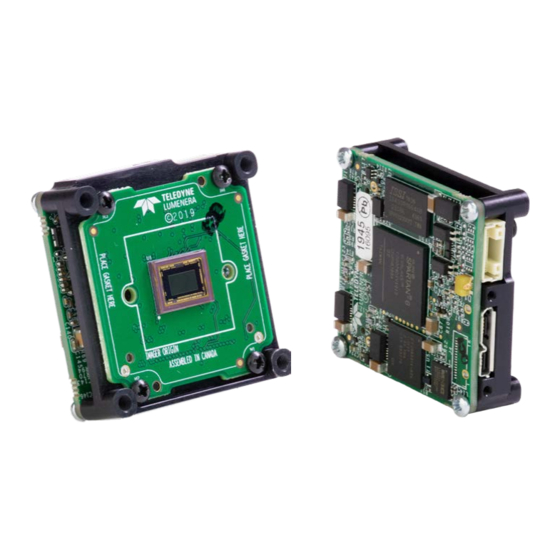
1 Board-Level Overview 1.1 Description Teledyne Lumenera USB 3 Vision compliant cameras provide a quick and easy means of capturing high quality images on any USB 3.0 equipped desktop, laptop or embedded computer. Because they are USB-based, there is no need for a frame grabber. Instead, a single cable provides full command control and data transfer at speeds of up to 380 MB/s (LT series). -
Page 7: Model Part Numbers
2464 x 2056 (IMX264) No casing No mount Lt-M3200B Sony 7.1M 1.1” LT-UM11-M320NBL 3216 x 2208 (IMX428) No casing No mount Lt-M3840B Sony 8.3M 1/1.8” LT-UM10-M384NBL 3840 x 2160 (IMX334) *RS No casing 2 • Board-Level Overview Teledyne Lumenera Lt Board-Level Series... -
Page 8: Color Cameras
4112 x2176 (IMX267) No casing No mount Lt-C4020B Sony 12.3M 1.1” LT-UC11-C402NBL 4112 x 3008 (IMX304) No casing No mount Lt-C5500B Sony 20M 1” LT-UC10-C550NBL 5472 x 3648 (IMX183) *RS No casing Teledyne Lumenera Lt Board-Level Series Board-Level Overview • 3... -
Page 9: Optional Accessories
USB 3.1 Cable A-Male to Micro-B male Locking (3m / 9.75ft) La303ML GPIO Sync cable, 9-Pin with I/O lead (power & lead cable) La4000PAFL See section Ruggedized Cable Accessories cabling options available directly from our preferred cable sources. 4 • Board-Level Overview Teledyne Lumenera Lt Board-Level Series... -
Page 10: Software Requirements
USB3 Vision and LuCam can be used with the Linux API. 1.3.1 Firmware Files for all Lt Models The latest firmware files for all Lt Models are available on the Teledyne Lumenera Lt Series support web site (subject to change): https://www.lumenera.com/support/industrial-usb-ethernet/drivers-downloads/usb3-camera- firmware-updater.html... -
Page 11: Series Specifications
FCC Class B & CE Certified, RoHS & WEEE Compliant Shock / Vibration EC60721-4-7 Class 7M2 & IEC60068-2-27 IEC60721-4-7 Class 7M2 & IEC60721-4-2 Class 2M2 Sinusoidal & Random Vibration IEC60068-2-6 & IEC60068-2-64 6 • Series Specifications Teledyne Lumenera Lt Board-Level Series... -
Page 12: Sensor Cosmetic Specifications
Lt-x4030B exposure 150 ms, gain 1, variable light source from dark to saturation • Lt-x4020B exposure 150 ms, gain 1, variable light source from dark to saturation • Lt-x5500B exposure 10 ms gain 1, variable light source from dark to saturation • Teledyne Lumenera Lt Board-Level Series Series Specifications • 7... -
Page 13: Mean Time Between Failure (Mtbf)
2.1.3 Mean Time between Failure (MTBF) Teledyne Lumenera MTBF calculations use the Parts Count/Parts Stress method. Calculated assembly FIT values are rounded up with margin to provide adequate headroom and the final quoted MTBF is then rounded down to the nearest year. -
Page 14: Sony Sensor Models
Yes – On Sensor, Vertical and Horizontal Binning Support Yes, monochrome model Multi-ROI Support Decimation Support Yes – ½x, vertical and horizontal On-Board Image Memory Yes (128 MB) Output Dynamic Range (dB) 72.7 dB 50.0 dB Teledyne Lumenera Lt Board-Level Series Sony Sensor Models • 9... -
Page 15: Quantum Efficiency Curves (Imx432)
3.1.1 Quantum Efficiency Curves (IMX432) The response curves describe the sensor, excluding lens and light source characteristics. Models – Monochrome Models – Color 10 • Sony Sensor Models Teledyne Lumenera Lt Board-Level Series... -
Page 16: Specifications: Lt-M1630 / Lt-C1630
Yes – On Sensor, Vertical and Horizontal Binning Support Yes, monochrome model Multi-ROI Support Decimation Support Yes, ½x Vertical and Horizontal On-Board Image Memory Yes (128 MB) Output Dynamic Range (dB) 72.7 dB 44.0 dB Teledyne Lumenera Lt Board-Level Series Sony Sensor Models • 11... -
Page 17: Quantum Efficiency Curves (Imx430)
3.2.1 Quantum Efficiency Curves (IMX430) The response curves describe the sensor, excluding lens and light source characteristics. Models – Monochrome Models – Color 12 • Sony Sensor Models Teledyne Lumenera Lt Board-Level Series... -
Page 18: Specifications: Lt-C1900
Image Correction Image Flip Support Yes, in-sensor, both vertical and horizontal Binning Support Multi-ROI Support Decimation Support On-board image memory Yes (128 MB) Output Dynamic Range 72.7 dB 40.5 dB Teledyne Lumenera Lt Board-Level Series Sony Sensor Models • 13... -
Page 19: Quantum Efficiency Curves (Imx327)
3.3.1 Quantum Efficiency Curves (IMX327) 14 • Sony Sensor Models Teledyne Lumenera Lt Board-Level Series... -
Page 20: Specifications: Lt-M1950 / Lt-C1950
Yes, In-Sensor, Vertical and Horizontal Binning Support Yes, monochrome model Multi-ROI Support Decimation Support Yes, ½x vertical and horizontal On-Board Image Memory Yes – 128 MB Output Dynamic Range (dB) 73.4 dB 40.2 dB Teledyne Lumenera Lt Board-Level Series Sony Sensor Models • 15... -
Page 21: Quantum Efficiency Curves (Imx392)
3.4.1 Quantum Efficiency Curves (IMX392) The response curves describe the sensor, excluding lens and light source characteristics. Models – Monochrome Models – Color 16 • Sony Sensor Models Teledyne Lumenera Lt Board-Level Series... -
Page 22: Specifications: Lt-M1980 / Lt-C1980
Yes, on sensor, vertical and horizontal Binning Support Yes, monochrome model Multi-ROI Support Decimation Support Yes, ½x, vertical and horizontal On-Board Image Memory 128 MB Output Dynamic Range (dB) 72.0 dB 43.9 dB Teledyne Lumenera Lt Board-Level Series Sony Sensor Models • 17... -
Page 23: Quantum Efficiency Curves (Imx429)
3.5.1 Quantum Efficiency Curves (IMX429) The response curves describe the sensor, excluding lens and light source characteristics. Models – Monochrome Models – Color 18 • Sony Sensor Models Teledyne Lumenera Lt Board-Level Series... -
Page 24: Specifications: Lt-M2020 / Lt-C2020
Image Flip Support Yes, In-Sensor, Vertical and Horizontal Binning Support Multi-ROI Support Decimation Support Yes, ½x vertical and horizontal On-Board Image Memory Yes (128MB) Output Dynamic Range (dB) 73.8 dB 41.1 dB Teledyne Lumenera Lt Board-Level Series Sony Sensor Models • 19... -
Page 25: Quantum Efficiency Curves (Imx265)
3.6.1 Quantum Efficiency Curves (IMX265) The response curves describe the sensor, excluding lens and light source characteristics. Models – Monochrome Models – Color 20 • Sony Sensor Models Teledyne Lumenera Lt Board-Level Series... -
Page 26: Specifications: Lt-M2420 / Lt-C2420
Yes, in sensor, Vertical and Horizontal Binning Support Multi-ROI Support Decimation Support Yes, ½x vertical and horizontal On-Board Image Memory 128 MB Output Dynamic Range (dB) 73.0 dB 40.2 dB Teledyne Lumenera Lt Board-Level Series Sony Sensor Models • 21... -
Page 27: Quantum Efficiency Curves (Imx264)
3.7.1 Quantum Efficiency Curves (IMX264) The response curves describe the sensor, excluding lens and light source characteristics. Monochrome Color 22 • Sony Sensor Models Teledyne Lumenera Lt Board-Level Series... -
Page 28: Specifications: Lt-M3200 / Lt-C3200
Yes, on sensor, vertical and horizontal Binning Support Yes, monochrome model Multi-ROI Support Decimation Support Yes, ½x vertical and horizontal On-Board Image Memory 128 MB Output Dynamic Range (dB) 72.4 dB 44.0 dB Teledyne Lumenera Lt Board-Level Series Sony Sensor Models • 23... -
Page 29: Quantum Efficiency Curves (Imx428)
3.8.1 Quantum Efficiency Curves (IMX428) The response curves describe the sensor, excluding lens and light source characteristics. Models – Monochrome Models – Color 24 • Sony Sensor Models Teledyne Lumenera Lt Board-Level Series... -
Page 30: Specifications: Lt-M3840 / Lt-C3840
Image Flip Support Yes in sensor, Vertical and Horizontal Binning Support Yes, color model Multi-ROI Support Decimation Support On-Board Image Memory Yes (128 MB) Output Dynamic Range (dB) 70.8 dB 38.5 dB Teledyne Lumenera Lt Board-Level Series Sony Sensor Models • 25... -
Page 31: Quantum Efficiency Curves (Imx334)
3.9.1 Quantum Efficiency Curves (IMX334) The response curves describe the sensor, excluding lens and light source characteristics. Monochrome Color 26 • Sony Sensor Models Teledyne Lumenera Lt Board-Level Series... -
Page 32: Specifications: Lt-M4030 / Lt-C4030
Yes in sensor, Vertical and Horizontal Binning Support Multi-ROI Support Decimation Support Yes, ½x vertical and horizontal On-Board Image Memory Yes (128 MB) Output Dynamic Range (dB) 73.3 dB 40.1 dB Teledyne Lumenera Lt Board-Level Series Sony Sensor Models • 27... -
Page 33: Quantum Efficiency Curves (Imx267)
3.10.1 Quantum Efficiency Curves (IMX267) The response curves describe the sensor, excluding lens and light source characteristics. Monochrome Color 28 • Sony Sensor Models Teledyne Lumenera Lt Board-Level Series... -
Page 34: Specifications: Lt-M4020 / Lt-C4020
Yes in sensor, Vertical and Horizontal Binning Support Multi-ROI Support Decimation Support Yes, ½x vertical and horizontal On-Board Image Memory Yes (128 MB) Output Dynamic Range (dB) 73.0 dB 40.1 dB Teledyne Lumenera Lt Board-Level Series Sony Sensor Models • 29... -
Page 35: Quantum Efficiency Curves (Imx304)
3.11.1 Quantum Efficiency Curves (IMX304) The response curves describe the sensor, excluding lens and light source characteristics. Monochrome Color 30 • Sony Sensor Models Teledyne Lumenera Lt Board-Level Series... -
Page 36: Specifications: Lt-M5500 / Lt-C5500
Image Flip Support Yes, on sensor, vertical and horizontal Binning Support Yes, in-sensor, continuous Multi-ROI Support Decimation Support On-Board Image Memory 128 MB Output Dynamic Range (dB) 71.7 dB 41.7 dB Teledyne Lumenera Lt Board-Level Series Sony Sensor Models • 31... -
Page 37: Quantum Efficiency Curves (Imx183)
3.12.1 Quantum Efficiency Curves (IMX183) The response curves describe the sensor, excluding lens and light source characteristics. Models – Monochrome Models – Color 32 • Sony Sensor Models Teledyne Lumenera Lt Board-Level Series... -
Page 38: Guide To Using A Rolling Shutter Camera
3.13 Guide to Using a Rolling Shutter Camera A few Lt Series cameras implement Sony rolling shutter sensors to achieve a high pixel density – low cost solution for a number of imaging implementations. These sensors have different usage characteristics and thus provide different application solutions compared to the Lt Series global shutter models. -
Page 39: Overview Of Electronic Rolling Shutter (Ers) Exposures
Strobe and Flash Zone (Lt-3840, Lt-5500) for settings. The dark environment illumination ensures minimal exposure (and thus minimal motion • artifacts) during the sensor lines integration time occurring before and after the flash period. 34 • Sony Sensor Models Teledyne Lumenera Lt Board-Level Series... -
Page 40: Overview Of Global Reset Release (Grr) Exposures
Therefore, as described previously, flash lighting in a dark environment is used to freeze • motion. The flash period matches the integration period for Line 1. The increasing exposures for the other sensor lines will not be visible without any other illumination source. Teledyne Lumenera Lt Board-Level Series Sony Sensor Models • 35... -
Page 41: Connecting The Camera
Sapera LT development environment. 4.2 Connecting Power Simple setups have a Lt Series camera powered directly by the USB3 port. This method provides a cabling solution for testing or for imaging installations where camera acquisitions are only software controlled and require no external I/O. -
Page 42: Led Status Indicator
Teledyne Lumenera LT-xx1x-xxxxx Series – Rear View 4.2.2 LED Status Indicator The Lt Series has one multicolor LED located on the back panel, to provide a simple visible indication of camera state, as described below. LED State Definition No power to the camera... - Page 43 Teledyne LUMENERA has performed ESD testing on cameras using an 8 kilovolt ESD generator without any indication of operational faults. The two following methods, either individually or together will prevent ESD problems. Method 1: Use a shielded/grounded power supply that connects to the ground pin of the I/O •...
-
Page 44: Feature Reference
5 Feature Reference 5.1 Lt Series Features The Teledyne Lumenera Lt Camera series feature set is presented in functional categories as grouped by the camera’s XML file. The USB3 GenICam control tool presents these features for the user to read or modify as required to explore the camera operation in the user’s imaging setup. -
Page 45: Camera Information Feature Descriptions
Indicates the minor version number of the 1.00 Minor Version GenICam XML. Invisible Device Manifest XML DeviceManifestXMLSubMinorVersion Indicates the subminor version number of the 1.00 Sub Minor Version GenICam XML. Invisible 40 • Feature Reference Teledyne Lumenera Lt Board-Level Series... -
Page 46: Sensor Control Category
5.3 Sensor Control Category These Lt Series controls group sensor specific parameters such as frame rate, exposure time & mode, gain, etc. Parameters shown on screen in gray are read only, either always or due to other feature settings. Features listed in the description table that are tagged as Invisible are usually for third party software usage—not typically needed by end user applications. - Page 47 Gain Selector GainSelector Selects which gain is controlled when adjusting gain 1.00 features. Beginner Gain will be applied to all channels or taps. 42 • Feature Reference Teledyne Lumenera Lt Board-Level Series...
-
Page 48: High Gain Conversion Mode
In normal to very bright lighting conditions, the saturation capacity of the sensor pixels should be maximized to provide the highest dynamic range. In this case, the high gain conversion mode should be disabled (High Gain Conversion Mode = Off). Teledyne Lumenera Lt Board-Level Series Feature Reference • 43... -
Page 49: I/O Control Category
A major device version release is shown in green. The last column also indicates whether the feature is a member of the DALSA Features Naming Convention (DFNC) or the GenICam Standard Features Naming Convention (SFNC, tag not shown). 44 • Feature Reference Teledyne Lumenera Lt Board-Level Series... - Page 50 Enables/disables the strobes in snapshot 1.00 mode. Beginner Strobe Is Off On Trigger OnTrigger Strobe fires on the trigger. 1.00 Strobe Delay StrobeDelay Trigger to strobe delay Beginner 1.00 Strobe Duration StrobeDuration Strobe length Beginner Teledyne Lumenera Lt Board-Level Series Feature Reference • 45...
- Page 51 ExposureActive Generate a signal that is active when the Exposure is active. Ready For Trigger ReadyForTrigger Generate a signal that is active when the camera is ready for a frame trigger. 46 • Feature Reference Teledyne Lumenera Lt Board-Level Series...
- Page 52 Pin 5 is the Signal, Pin 2 and 6 are the – Pin1=Pwr ground and Pin 1 is the common output Power on the I/O connector. Pin3=3.3V Pin3Power Pin 3 is the 3.3V optional output Power on the I/O connector. Teledyne Lumenera Lt Board-Level Series Feature Reference • 47...
-
Page 53: Input And Output Line Details
4. Set Output Line Source to Pulse on: Start of Exposure. 5. Set Output Line Pulse Delay to the value found in Flash Zone Delay. 6. Set Output Line Pulse Duration to the value found in Flash Zone Duration. 48 • Feature Reference Teledyne Lumenera Lt Board-Level Series... -
Page 54: Advanced Processing Control Category
Parameters in gray are read only, either always or due to other feature settings. Parameters in black are user set. Features listed in the description table that are tagged as Invisible are usually for third party software usage—not typically needed by end user applications. Teledyne Lumenera Lt Board-Level Series Feature Reference • 49... -
Page 55: Advanced Processing Control Feature Descriptions
GREEN gain is controlled by Balance Ratio. Blue Blue BLUE gain is controlled by Balance Ratio. Balance Ratio BalanceRatio Sets the digital gain of the selected color 1.00 component (BalanceRatioSelector). Expert 50 • Feature Reference Teledyne Lumenera Lt Board-Level Series... -
Page 56: Image Format Control Category
5.6 Image Format Control Category The LT Series Image Format control has parameters used to configure camera pixel format, image cropping, decimation and others. Parameters in gray are read only, either always or due to another parameter being disabled. Parameters in black are user set. - Page 57 Invisible vertical dimension of the image. Pixel Color Filter PixelColorFilter Indicates the type of color filter applied to the 1.00 image. Invisible None None No color filter. 52 • Feature Reference Teledyne Lumenera Lt Board-Level Series...
-
Page 58: Width And Height Features For Partial Scan Control
Increase the exposure time, decrease the frame rate, or acquire a limited number of frames, so as to not exceed the transfer bandwidth. Teledyne Lumenera Lt Board-Level Series Feature Reference • 53... -
Page 59: Horizontal Cropping (Partial Scan)
5.6.2.2 Horizontal Cropping (Partial Scan) Lt Series cameras support cropping the acquisition horizontally by grabbing fewer pixels on each horizontal line. Horizontal offset defines the start of the acquired video line while horizontal width defines the number of pixels per line. - Page 60 Acquisition Flip Features Horizontal Flip (Mirror) Both Horizontal & Vertical Flip Vertical Flip Teledyne Lumenera Lt Board-Level Series Feature Reference • 55...
-
Page 61: Acquisition Control Category
1.00 capture during an acquisition and the way the Beginner acquisition stops. Continuous Continuous Frames are captured continuously until stopped with the AcquisitionStop command. 56 • Feature Reference Teledyne Lumenera Lt Board-Level Series... - Page 62 Registers Check DeviceRegistersCheck Performs an explicit register set validation for 1.00 consistency. Invisible States if the current register set is valid and 1.00 Registers Valid DeviceRegistersValid consistent. Invisible Teledyne Lumenera Lt Board-Level Series Feature Reference • 57...
-
Page 63: Event Control Category
Parameters in black are user set. Features listed in the description table that are tagged as Invisible are usually for third party software usage—not typically needed by end user applications. 58 • Feature Reference Teledyne Lumenera Lt Board-Level Series... -
Page 64: Event Control Feature Descriptions
Represents the event ID to identify the 1.00 EventExposureEnd software Event. Guru Exposure End Data EventExposureEndData Data of the exposure end event 1.00 Guru Exposure End Event EventExposureEndTimestamp Timestamp of the EventExposureEnd event. 1.00 Timestamp Guru Teledyne Lumenera Lt Board-Level Series Feature Reference • 59... -
Page 65: Transport Layer Control Category
Beginner Low Speed LowSpeed Full Speed FullSpeed High Speed HighSpeed Super Speed SuperSpeed 1.00 PayloadSize Provides the number of bytes transferred for Invisible each image or chunk on the stream channel. 60 • Feature Reference Teledyne Lumenera Lt Board-Level Series... -
Page 66: Teledyne Lumenera Control Category
LuCam mode in troubleshooting for information and methods required to switch a camera mode. 5.10.1 Teledyne Lumenera Control Feature Descriptions The following table describes the features and values found in the category, as well as the device version and visibility level (beginner, expert, guru, invisible). The device version represents a camera software functional level (different from the firmware revision number) and may differ for each camera sensor. -
Page 67: File Access Control Category
FileOperationExecute. Close Close Select the Close operation – executed by FileOperationExecute Read Read Select the Read operation – executed by FileOperationExecute. Write Write Select the Write operation – executed by FileOperationExecute. 62 • Feature Reference Teledyne Lumenera Lt Board-Level Series... - Page 68 Displays the file operation result. For Read or Write Guru operations, the number of successfully read/written bytes is returned. 1.00 File Size FileSize Represents the size of the selected file in bytes. Guru Teledyne Lumenera Lt Board-Level Series Feature Reference • 63...
-
Page 69: File Access Via The Camexpert Tool (Quick Camera Firmware Upgrade)
From the File selector list, choose Firmware. • Click Browse to open Windows Explorer. • Select the .cbf firmware file to upload. • Click Upload (to Camera) to execute the file transfer to the camera. • 64 • Feature Reference Teledyne Lumenera Lt Board-Level Series... -
Page 70: Usb3 Vision Host Controls Category
The USB3 Vision Host Controls group parameters are used to configure the host computer system features for camera communication management. None of the parameters are stored in the camera. The features allow optimizing the configuration for maximum bandwidth. Teledyne Lumenera Lt Board-Level Series Feature Reference • 65... -
Page 71: Technical Specifications
Serial number Barcode FCC and CE logo Made in Canada Additional Mechanical Notes Lt camera series supports a screw lock USB3 cable as described in Ruggedized Cable Accessories Ruggedized Cable Accessories. 66 • Technical Specifications Teledyne Lumenera Lt Board-Level Series... -
Page 72: Mechanical Specifications
6.2 Mechanical Specifications Teledyne Lumenera Lt Board-Level Series Technical Specifications • 67... -
Page 73: Temperature Management
6.3 Temperature Management Lt Series cameras are designed to optimally transfer internal component heat to an outer metallic structure. If the camera is free standing (i.e. not mounted) it will be very warm to the touch. Basic heat management is achieved by mounting the camera onto a metal structure via its mounting screws. -
Page 74: Connectors
Bi-directional general purpose I/O #2 terminal GPIO3 Bi-directional general purpose I/O #3 terminal External power ground reference terminal Opto GND External ground reference for Opto signal Opto Output Optically isolated output Opto Input Optically isolated input Teledyne Lumenera Lt Board-Level Series Technical Specifications • 69... -
Page 75: Bi-Directional I/O Dc Specifications
The example uses a 5 V bias supply (output referenced to 5 V) and a 220 Ω series resistor. When using a 12 V bias supply (for Vcc) a 560 Ω resistor is suggested. • The output signal swings between Vcc and ground. • 70 • Technical Specifications Teledyne Lumenera Lt Board-Level Series... -
Page 76: Computer Requirements For Lt Cameras
6.6 Computer Requirements for Lt Cameras A USB 3.0 equipped desktop, laptop or embedded computer will have the 5 volt power supply • required by the Lt Series cameras. The computer requires the Windows 10 or Linux operating system. •... -
Page 77: Ec & Fcc Declarations Of Conformity
6.7 EC & FCC Declarations of Conformity 72 • Technical Specifications Teledyne Lumenera Lt Board-Level Series... -
Page 78: Additional Reference Information
Information 7.1 Choosing a Lens with the Correct Image Circle Each Lt Series model requires a lens with an image circle specification to fully illuminate the sensor. The following section graphically shows the minimum lens image circle for each model family along with alternative lens types. -
Page 79: Lens Options For Lt-1950
The following figure shows the lens image circles relative to these models, in color or • monochrome versions. A 1/1.8” lens can be used with these models. • 1/1.8" Lens (~9mm) Image Circle 2/3" Lens (~11mm) Image Circle 1" Lens (~16mm) Image Circle 74 • Additional Reference Information Teledyne Lumenera Lt Board-Level Series... -
Page 80: Lens Options For Lt-1980, Lt-2420
The following figure shows the lens image circles for this model, in color or monochrome • versions. • A 1/1.7” lens can be used with this model. 1/1.7" Lens (~9mm) Image Circle Model 1630 2/3" Lens (~11mm) Image Circle 1" Lens (~16mm) Image Circle Teledyne Lumenera Lt Board-Level Series Additional Reference Information • 75... -
Page 81: Lens Options For Lt-4030, Lt-5500
The following figure shows the lens image circles relative to these models, in color or • monochrome versions. A typical 1.1” lens will illuminate these sensors. • 1.3" Lens (~22.5mm) Image Circle 1.1" Lens (~17mm) Image Circle 76 • Additional Reference Information Teledyne Lumenera Lt Board-Level Series... -
Page 82: Additional Lens Parameters (Application Specific)
The Teledyne DALSA Web site provides an introduction to this potentially complicated issue along with many other application notes and guides on machine vision. Start with this Knowledge Center article: http://www.teledynedalsa.com/en/learn/knowledge-center/machine-vision-101-an-... -
Page 83: Light Sources
Using rubber finger cots and rubber gloves can prevent oil contamination. However, the friction between the rubber and the window may produce electrostatic charge that may damage the sensor. 78 • Additional Reference Information Teledyne Lumenera Lt Board-Level Series... -
Page 84: Cleaning The Sensor Window
• 7.4 Ruggedized Cable Accessories Teledyne provides optional I/O cable assemblies for Lumenera Lt. Users wishing to build their I/O cabling by starting from available cable packages should consider these popular assemblies described below. Contact Sales for pricing and delivery. -
Page 85: Long Passive Cables And Optical Cables
USB3 Long Distance Active Cables CEI's USB3 BitMaxx cables offer Plug & Play active cable solutions for USB Vision. Please visit the web site for Components Express to review their cable options. https://www.componentsexpress.com/_Bit_MAXX-long-distance-usb3-cables 80 • Additional Reference Information Teledyne Lumenera Lt Board-Level Series... -
Page 86: Troubleshooting
There are not enough computer resources to keep up with the current camera data rate. You • will need to minimize the resource usage or operate the camera on a faster computer which easily handles the continuous video stream on the USB3 port. Teledyne Lumenera Lt Board-Level Series Troubleshooting • 81... -
Page 87: Using The U3V Device Manager Tool
Select the connected camera, select the drive to switch too and click on Switch Protocol. 8.4 Switching a Lumenera camera from LuCam mode to USB3 Vision mode Go to the Teledyne Lumenera web site and register your name and password to login and • access the download area. [ www.lumenera.com ] Go to /Home/Support/Industrial (USB &... -
Page 88: Switching A Lumenera Camera From Usb3 Vision Mode To Lucam Mode
This procedure describes how to change mode with Sapera Lt CamExpert. You can also change it with a USB3 Vision compliant third-party tool using the same features. Run CamExpert and select the Teledyne Lumenera Control category. • Change the Camera Boot Sequence value from USB3Vision to LuCam. -
Page 89: Chart 1
8.6.1 Chart 1 84 • Troubleshooting Teledyne Lumenera Lt Board-Level Series... -
Page 90: Chart 2
8.6.2 Chart 2 Teledyne Lumenera Lt Board-Level Series Troubleshooting • 85... -
Page 91: Chart 3
8.6.3 Chart 3 86 • Troubleshooting Teledyne Lumenera Lt Board-Level Series... -
Page 92: Chart 4
8.6.4 Chart 4 Teledyne Lumenera Lt Board-Level Series Troubleshooting • 87... -
Page 93: Revision History
9 Revision History Revision Date Major Change Description February 9, 2021 Preliminary Internal Version June 16, 2021 Addition of new models and related updates. A few corrections to model specifications. 88 • Revision History Teledyne Lumenera Lt Board-Level Series... -
Page 94: Contact Information
Submit any support question or request via our web site: Technical support form via our web page: Support requests for imaging product installations, https://www.lumenera.com/support/about- Support requests for imaging applications technical-support.html Camera support information lumenera.support@teledyne.com Product literature and driver updates Teledyne Lumenera Lt Board-Level Series Contact Information • 89...
Need help?
Do you have a question about the Lt Series and is the answer not in the manual?
Questions and answers