Table of Contents
Advertisement
Quick Links
Advertisement
Table of Contents

Subscribe to Our Youtube Channel
Related Manuals for Teledyne EV71YC4MNT4005-BA0


Summary of Contents for Teledyne EV71YC4MNT4005-BA0
-
Page 1: User Manual
USER MANUAL ELIIXA+ NBase-T MONOCHROME e2v.com/cameras... -
Page 2: Table Of Contents
Table of Contents 1 Camera Overview ........................5 1.1 Features ................................. 5 1.2 Key Specifications ............................5 1.3 Description..............................6 1.4 Applications ..............................6 1.5 Models ................................6 2 Camera Performances ......................7 2.1 Camera Characterization ..........................7 2.2 Image Sensor ..............................7 2.3 Sensor modes .............................. - Page 3 7.3 Transport Layer Control ..........................24 7.4 Acquisition Control ............................27 7.4.1 GenICam Triggers ..........................27 7.4.2 Cycling Preset modes and configuration ....................31 7.4.3 Full Exposure Control Mode ......................... 33 7.5 Digital I/O Control ............................35 7.6 Enhanced Features Control ......................... 40 7.6.1 Rotary Encoder, Rescaler and Frame Delay..................
- Page 4 E.3 Ethernet Cable ............................. 66 E.4 PureGev Application and eBus Package ...................... 67 E.5 Driver Configuration and Inter-Operablity ....................67 Appendix F. Revision History ....................68 UM_EL XA+_NBASE-T_M REV.B 03/2018 A G E...
-
Page 5: Camera Overview
1 Camera Overview 1.1 Features Cmos Multi-Lines Monochrome Sensor : 4 x 4096 Pixels 5x5µm 4096 RGB Pixels 5x5µm (Full Definition) in 1,2 or 4 Lines Summation 2048 RGB Pixels 10x10µm (Binning) in 1 or 2 lines Summation ... -
Page 6: Description
High resolution document scanning Printing inspection Industrial Inspection 1.5 Models Part Number Definition Max Speed Details EV71YC4MNT4005-BA0 4k x 5µm 140kHz Delivered with a pair of Heat Sinks EV71YC4MNT2010-BA0 2k x 10µm 140kHz UM_EL XA+_NBASE-T_M REV.B 03/2018 A G E... -
Page 7: Camera Performances
2 Camera Performances 2.1 Camera Characterization 4k 5µm 2k 10µm Unit Mode 1S (0dB) Mode 2S (0dB) Mode 4S (0dB) Mode 1SB Mode 2SB (0dB) (0dB) Typ. Typ. Typ. Typ. Typ. Dark Noise RMS Dynamic Range 2394:1 3412:1 2730:1 2730:1 2730:1 Readout Noise Full Well Capacity... -
Page 8: Sensor Modes
2.3 Sensor modes 4K Pixels Output Mode 1S = B Mode 2S = B+C (FPGA) Mode 4S = (A.B)+(C.D) Note : (A.B) = summation in the sensor 2k Pixels Output Mode 1SB = A Mode 2SB = (A+B) 2.4 Response & QE curves 2.4.1 Quantum Efficiency Quantum Efficiency 1060... -
Page 9: Spectral Responses
2.4.2 Spectral Responses Single Modes : 1S, 2S, 4S Response in 4k Pixels 5µm LSB12bits/(nJ/cm2)) 1000 1050 1100 Binning Modes : 1SB, 2SB Response in 2k Pixels 10µm LSB12bits/(nJ/cm2)) 1200 1100 1000 1000 1050 1100 UM_EL XA+_NBASE-T_M REV.B 03/2018 A G E... -
Page 10: Camera Hardware Interface
3 Camera Hardware Interface Sensor alignment Z = -10.3 mm ±100µm X = 19.76 mm (4k 5µm) ±100 µm X = 19.76 mm (2k 10µm) Y = 30 mm ±100 µm Die flatness 50 µm Rotation (X,Y plan) ±0.3° Parallelism 50µm UM_EL XA+_NBASE-T_M... -
Page 11: Input/Output Connectors And Led
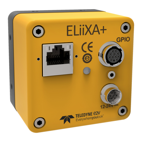
3.1 Input/output Connectors and LED GPIO Connector Hirose 12 pts Ethernet RJ45 Connector with Traffic & Connection LED Multi-Coloured LED for Status and diagnostic Power Connector : 12-24V DC 3.2 Power Connector Camera connector type: Hirose HR10A-7R-6PB (male) Cable connector type: Hirose HR10A-7P-6S (female) Signal Signal Power supply from 12 to 24V... -
Page 12: Status Led Behaviour
110mA The complete Boot sequence : 90mA No real peak of Inrush current 110mA 430m Several steps up to the nominal current (about 430mA under 24V) 120mA 12.1 13.2 2.9s If the NIC Board (on PC Side) is not forced at 5Gb/s (no Auto-Negotiation or 10Gb/s) then a peak of 1,5A can be observed at the boot on the camera power Supply. - Page 13 Lines 0, 1 and 2 The GPIO Connector allows the following connections : Line 0, 1 or 2 : Dedicated inputs for Line Triggers and Frame Trigger. Differential (RS422 with or without termination) or TTL (Single End) in 3.3V, 5V, 12V or 24V. Input Unit Thresholds...
-
Page 14: Standard Conformity
4 STANDARD CONFORMITY The ELIIXA+ cameras have been tested using the following equipment: A shielded power supply cable A GigE cat 5E data transfer cable ref. e2v recommends using the same configuration to ensure the compliance with the following standards. 4.1 CE Conformity The ELIIXA+ cameras comply with the requirements of the EMC (European) directive 2004/108/EC (EN50081-2, EN 61000-6-2). -
Page 15: Camera Interface : Nbase-Ttm
5 Camera Interface : NBASE-T 5.1 What is the NBASE-T Technology ? NBASE-T™ technology defines a new type of Ethernet signaling that boosts the speed of installed based twisted-pair cabling well beyond the cable’s designed limit of 1 Gigabit per second (Gbps) for distances up to 100 meters. -
Page 16: Camera Interface Overview
6 Camera Interface Overview 6.1 Inputs, Outputs and Enhanced Features The Digital I/O Module allows the connection of 7 external Lines : 3 dedicated inputs (Line 0, 1 and 2) that can generate 2 Line Triggers (LT1 and LT2) and one Frame Trigger (FT) that will be used as inputs in the Enhanced features Block. - Page 17 A cycling mode which allows looping over a sequence of up to 8 Steps the 4 Possible Presets of Parameters (Gain, Exposure Time and Delay, FFC, LUT …) Up to 4x Region of Interests with separate FFC can be selected for Output ...
-
Page 18: Camera Commands
7 Camera Commands 7.1 Device Control Size GenCP address GenICam Register R/W Description (Bytes) 0x11030 DeviceScanType AreaScan (0) or LineScan (1) 0x0048 DeviceVendorName 0x0068 DeviceModelName NBASE_T_MONO 0x00A8 DeviceManufacturerInfo Camera Part Number : EV71C4MNTxxxx-BA0 0x0088 DeviceVersion Camera Firmware Version 0x00D8 DeviceSerialNumber Camera Serial Number : YYWWAxxxx 0x00E8 DeviceUserID... -
Page 19: Image Format Control
7.2 Image Format Control This section includes all the settings relative to the Image Format and size. 7.2.1 Image Format Height : Set the Height of the Image, but also the Buffer’s Heights in the Application. From 1 to 16383 ... -
Page 20: Meta Data
7.2.2 Meta Data When enabled, Meta Data are added at the End of Each Line for a total of 24 Bytes (or 24 Pixels 8bits) In the table below : M0/M1/M2… are the 8bits components of each Pixel Pixel n° Component Data Name... -
Page 21: Regions Of Interest
There are three different possible outputs when the HDR mode is set : Single Line Bottom only : Line “C” only is outputted to check the High Levels Single Line Top only : Line “A+B” is outputted to check the Low Levels ... - Page 22 Size GenCP address GenICam Register R/W Description (Byte 0x12500 SensorWidth Active Pixels number of the Sensor 0x12500 Width Total Pixels number outputted including MetaData Set the Height of the image (1 to 16383) 0x12510 Height Mono8, Mono10, Mono10Packed, Mono12, Mono12Packed 0x12540 PixelFormat PixelSize...
- Page 23 Set the number of ROI : 0 : No ROI. Default output is the full Sensor Width 0x4E0582CC ROI_Number 1 to 4 : 1 to 4 ROI with no possible Overlap ROI1 to ROI4 ROISelector Set the Pixel Start of ROI1 (0 to SensorWidth-1) 0x4E0582D4 ROI1_Start Set the Pixel Width of ROI1 (0 to SensorWidth-1)
-
Page 24: Transport Layer Control
7.3 Transport Layer Control These are the standard and required parameters for the Ethernet Transport Layer. Size GenCP address GenICam Register R/W Description (Byte Payload Size calculated from : 0x200134F8 PayLoadSize PixelFormat x Width x Height GigE Vision 0x0968 GevPhysicalLinkConfiguration SingleLink 0x0004 GevCurrentPhysicalLinkConfiguration... - Page 25 6 : Within 25µs 7 : Within 100µs 8 : Within 250µs 9 : Within 1ms 10 : Within 2.5ms 11 : Within 10ms 12 : Within 25ms 13 : Within 100ms 14 : Within 250ms 15 : Within 1s 16 : Within 10s 17 : Greater than 10s 18 : Alternate PT Profile...
- Page 26 Controls the port of the selected channel to 0x0D00 GevSCPHostPort which a GVSP transmitter must send data stream Sends a test packet 0x0D04 GevSCPSFireTestPacket 0: Off 1 : On Used by the application to prevent IP 0x0D04 GevSCPSDoNotFragment fragmentation of packets on the stream channel : 0: Off 1 : On...
-
Page 27: Acquisition Control
7.4 Acquisition Control 7.4.1 GenICam Triggers Four GenICam Triggers can be configured : Line Start Trigger : Start the Line on an Edge variation of the Source Exposure Active Trigger : Exposure active on a certain Level of the Source ... - Page 28 Size R/W Description GenCP GenICam Register (Bytes) address 0: Continuous 0x13100 AcquisitionMode 1 : Single Frame 2: Multi Frame 3 : Single Frame Recording 4: Single Frame Readout 0x13110 AcquisitionStart Command : Not readable 0x13120 AcquisitionStop Command : Not readable Number of Frame to Acquire in “Multi Frame”...
- Page 29 0 : Off (The Trigger Mask is disabled) 4 : FLO (Exposure Active in the Sensor) 5 : Counter 1 End 6 : Counter 2 End 7 : Timer 1 End 8 : Timer 2 End 9 : L3 10 : L4 11 : L5 12: L6 13 : Frame Valid...
- Page 30 5 : Counter 1 End 6 : Counter 2 End 7 : Timer 1 End 8 : Timer 2 End 9 : Line 3 10 : Line 4 11 : Line 5 12: Line 6 13 : Frame Valid 14 : Acquisition Active Validation of the Frame Active Trigger (disabled if the 0x4E058498 TriggerMode_FrameActive...
-
Page 31: Cycling Preset Modes And Configuration
7.4.2 Cycling Preset modes and configuration The Cycling Preset mode is the possibility for the camera to switch at least for each line between 4x sets of pre-defined parameters including : Exposure Time and Exposure Delay Flat Field Correction ... - Page 32 3 : Preset 1, 2 and 3 are used 4 : Preset 1, 2, 3 and 4 are used Activation Edge for the next repeater: 0x4E058210 CyclingPresetEdge 0 : Falling Edge 1 : Rising Edge Restart Cycling Sequence from Repeater 0 at : 0x4E0581E8 CyclingPresetSynchronization 0 : Next Line...
-
Page 33: Full Exposure Control Mode
7.4.3 Full Exposure Control Mode The Full Exposure Control In Full Definition Enhanced Sensor Mode, the Sensor is working as a double TDI (Time Integration Delay) : The two Top Pixels and the two bottom Pixels are working together in TDI with a delay between their exposure and outputting by the same Memory node and ADC. - Page 34 Zone 3 : If Tper >= 4 x Max (TPer , Prog_Tint) + 10µs mini The risk is the sensor saturates then the calculation above is no more valid : after showing an incorrect white balance, the image level will decrease down to 0 as the Line Period is increasing. ...
-
Page 35: Digital I/O Control
7.5 Digital I/O Control This Digital I/O Module allows to setup and transformed the 7 I/O Lines of the I/O Connector in useful internal signals : Line 0, 1 and 2 are preferred inputs (only inputs) to set the three internal Signals : Line Trigger 1 and 2 (LT1, LT2) and Frame Trigger (FT) ... - Page 36 Size GenCP address GenICam Register R/W Description (Byte Input Lines Internal Signals Source Select the Source for Line Trigger 1 (LT1) : 0x4E0582F4 IOSource_LT1 Line0 Line1 Line2 Select the Source for Line Trigger 2 (LT2) : 0x4E0582F8 IOSource_LT2 ...
- Page 37 Line Inverter Invert the Line Trigger 1 Signal : 0x4E0584E8 LineInverter_LT1 0 : Off 1 : On Invert the Line Trigger 2 Signal : 0x4E0584EC LineInverter_LT2 0 : Off 1 : On Invert the Line Frame Trigger Signal : 0x4E0584F0 LineInverter_FT 0 : Off 1 : On...
- Page 38 Size GenCP address GenICam Register R/W Description (Byte Line Detection Set the detection Level of the Line 0 : 0x4E0582A0 LineDetectionLevel_L0 0 : 3.3v 1 : 5v 2 : 12v 3 : 24v Set the detection Level of the Line 1 : 0x4E0582A4 LineDetectionLevel_L1 0 : 3.3v...
- Page 39 Size GenCP address GenICam Register R/W Description (Byte Output Lines Line Output Level Set Line 3 Output Level: 0x4E0582BC LineOutputLevel_L3 0 : 3.3V 1 : 5V 2 : Power (defined by the Voltage supplied to the Camera) Set Line 4 Output Level: 0x4E0582C0 LineOutputLevel_L4 0 : 3.3V...
-
Page 40: Enhanced Features Control
7.6 Enhanced Features Control 7.6.1 Rotary Encoder, Rescaler and Frame Delay The Embedded Rotary Encoder is managed by the two inputs Lines : LT1 taken as “A” quadrature input LT2 taken as “B” quadrature input Mode The Encoder takes in account the Forward/Reverse indication given to the camera (by software or external input) to determine “A”... -
Page 41: Counters & Timers
5 : 32 6 : 64 7 : 128 Enables the Rescaler : 0x4E058334 RescalerEnable 0 : Disabled 1 : Enabled Frame Trigger Delay Control Number of Last Triggers to Average : 0x4E058318 FrameTriggerDelaySource 0 : Time Base (µs) 1 : Time Base (ms) 2 : LT1 Rising Edge 3 : LT1 Falling Edge 4 : RO Rising Edge... - Page 42 reaches the duration before any reset, the output rises to 1 and the counter carries on counting. Then if the Reset arises, the “Value at Reset” is set with the current value (even higher than the duration), the output is set to 0 and the counter can restart counting on the same even as soon as the reset input switches down to 0.
- Page 43 7 : Timer 1 End 8 : Timer 2 End 9 : L3 10 : L4 11 : L5 12: L6 13 : Frame Valid 14 : Acquisition Active 15 : Software (Use Counter1Software register) Set the Counter 1 Reset Activation mode : 0x4E0583B4 Counter1ResetActivation 0 : Rising Edge...
- Page 44 2 : Any Edge Set the Source for the Counter 2 Reset : 0x4E0583B0 Counter2ResetSource 0 : Off 1 : Line Trigger 1 2 : Line Trigger 2 3 : Frame Trigger 5 : Counter 2 End 7 : Timer 1 End 8 : Timer 2 End 9 : L3 10 : L4...
- Page 45 Size GenCP address GenICam Register R/W Description (Byte Timer 1 Event Source to Start the Timer 1 : 0x4E0583DC Timer1TrigSource 1 : Line Trigger 1 2 : Line Trigger 2 3 : Frame Trigger 5 : Counter 1 End 6 : Counter 2 End 8 : Timer 2 End 9 : L3 10 : L4...
- Page 46 9 : L3 10 : L4 11 : L5 12: L6 13 : Frame Valid 14 : Acquisition Active 15 : Software (Use Timer1LockSoftware register) 16 : Rotary Encoder Output Set the Timer 1 Lock Activation mode : 0x4E06065C Timer1LockActivation 3 : Level High 4 : Level Low Software Register to Lock Timer 1...
- Page 47 0x4E058518 Timer2Reset Software command for a Reset Source set to Software Set the Source for the Timer 2 Lock : 0x4E060660 Timer2LockSource 0 : Off 1 : Line Trigger 1 2 : Line Trigger 2 3 : Frame Trigger 4 : FLO (Exposure Active in the Sensor) 6 : Counter 2 End 8 : Timer 2 End 9 : L3...
-
Page 48: Gain Control
7.7 Gain Control This section includes only the two main gains which have a global action on the whole sensor line : The Pre-Amplification Gain (considered as the only Analog Gain as it takes place in the sensor during the ADC conversion) and which is detailed below. - Page 49 GenCP address GenICam Size R/W Description command Pre-amplifier gain to: 0x4E05803C PreAmpGain 0 : x1 1 : x2 2 : x4 3 : x8 0x4E058028 GainAll_PR1 Preset 1 (Cycling Mode) and default Digital gain from 0dB (0) to +8dB (6193) : (1 + <Val>l/4096) 0x4E05802C GainAll_PR2 Preset 2 (Cycling Mode)
-
Page 50: Flat Field Correction Control
7.8 Flat Field Correction Control How is performed the Flat Field Correction ? What is the Flat Field correction (FFC) ? The Flat Field Correction is a digital correction on each pixel which allows : To correct the Pixel PRNU (Pixel Response Non Uniformity) and DSNU (Dark Signal Non Uniformity) ... - Page 51 How to perform the Flat Field Correction ? Don’t forget first to setup the Cycling Preset Selector (Acquisition Control / Cycling Preset) in order to select in which Preset (1, 2, 3, 4 or All) you’ll save the result of your FFC once calculated. If the Cycling Preset Mode is not activated, by default it will be saved in Preset 1.
-
Page 52: Prnu Low Frequency Filter For Ffc
7.8.1 PRNU Low Frequency Filter for FFC The FFC Low Band Filter allows an easier make in use of the FFC (PRNU Part) : You can use a non-moving paper and you can filter the defects of these paper before the FFC calculation in order to not take them in account. The command “LowFilterWidth”... - Page 53 GenCP address GenICam command Size R/W Description PRNUCalibrationAbort Set to 1 to abort PRNU calibration 0x4E058454 Width of the low filter for PRNU calculation : 0x4E05844C LowFilterWidth 0 is for a disabled filter. 1 to 63 for a Filter Interval of [-<val> , +<Val>] Enables the FFC Adjust Gain : 0x4E0626C4 FFCAdjustEnable...
-
Page 54: Look Up Table
7.9 Look Up Table The User can define an upload a LUT in the Camera that can be used at the end of the processing. The LUT is defined as a correspondence between each of the 4096 gray levels (in 12 bits) with another outputted value. -
Page 55: Device Access Control
7.10 Device Access Control Set the Privilege access of the Camera (only Integrator User) GenCP address GenICam Command Size Description Display the current Privilege Level : 0x4E0580BC CameraPrivilegeLevel 0 : Factory Mode 1 : Integrator Mode 2 : User Mode Set the Privilege Level : 0x4E0580C0 ChangePrivilegeLevel... - Page 56 GenCP address GenICam Command Size Description Flat Field Correction Restore FFC User Bank : 0x4E058480 UserFFCBankRestore 0 : Default (Factory) 1 – 4 : User Banks Save FFC User Bank : 0x4E05847C UserFFCBankSave 1 – 4 : User Banks Get the Current FFC Bank in Use : 0x4E058484 CurrentFFCBank 0 : Default (Factory)
-
Page 57: Appendix
APPENDIX UM_EL XA+_NBASE-T_M REV.B 03/2018 | 57 A G E... -
Page 58: Appendix A. Pattern Tests
Appendix A. Pattern Tests A.1 Test Pattern 1: Vertical wave The Test pattern 1 is a vertical moving wave : each new line will increment of 1 grey level in regards with the previous one : level reaches 255 before switching down to 0 A.2 Test Pattern 2: Fixed Horizontal Ramps Starting at 0, an increment of 1 LSB is made every 16 pixels. -
Page 59: Appendix B. Timing Diagrams
Appendix B. Timing Diagrams B.1 Synchronization modes with variable Exposure Time Synchro Mode Line Trigger Ext. or Internal Exposure Mode Timed (Exposure Time) Exposure Time Exposure Time Programmed Programmed ITC Trigger intProg Exposure as Ext. Line Trigger Mode TriggerWidth Tint real Exposure Time Internal... -
Page 60: Synchronization Modes With Fixed Exposure Time
B.2 Synchronization modes with Fixed Exposure Time Synchro Mode Line Trigger Ext. or Internal Exposure Mode Off Tint real Exposure Time In the Internal Camera / sensor Digital Conversion Digital Conversion In these modes, the rising edge of the Trigger (internal or External) starts the readout process (T ) of the previous integration. -
Page 61: Appendix C. Hdr Mode
Appendix C. HDR Mode C.1 HDR Block With the HDR Single Line Mode, the “HDR” is calculated in the camera as following : Line C (8bit) (12bit) Processing : Camera output FFC, HDR bloc interface HDR Output Gain (8, 10, 12bit) (12bit) Lines AB (8bit) (12bit) -
Page 62: Hdr With Lut 10Bits => 8Bits
C.3 HDR With LUT 10bits => 8bits Camera output The LUT could be used to compress the HDR output in 8bit. 1023 Camera 10b output without LUT Camera 8b output with 10b8b LUT illumination Saturation Lines AB Saturation Line C Lines AB used Line C used C.4 Example of difference between “AB”... -
Page 63: Appendix D. Accessories
Appendix D. Accessories D.1 F-Mount F Mount: (Part number EV50-MOUNT-F) Drawing for the additional part (except Nikon BR3) : UM_EL XA+_NBASE-T_M REV.B 03/2018 | 63 A G E... -
Page 64: C-Mount
D.2 C-Mount C Mount : (Part number EV71-C-MOUNT) UM_EL XA+_NBASE-T_M REV.B 03/2018 | 64 A G E... -
Page 65: Set Of Heatsinks
D.3 Set of Heatsinks The ELIIXA+ NBASE-T Cameras are already delivered with 2 Heat Sinks, but if necessary, additional heat sinks are available (set of 2) and they can be fixed on any side of the front face : Set of 2 x Heat Sinks : Part number AT71KFPAVIVA-CAA The Camera has been designed to dissipates the maximum of the internal heat through its front face : The packaging of the sensor is larger to increase the surface in contact with the front face and then improves the dissipation. -
Page 66: Appendix E. Network Connection
Appendix E. Network Connection 2x Kits including NBase-T Board and cables (power + Trigger) are available : E.1 Single Network Board + Cables (GPIO + Power) Kit This kit includes : One Single NBase-T (5/10GigE) board (N480) One set of 2 cables (GPIO + Power supply). Part number : EV0A0000-0NTCKA0-U Contact the Customer Service for more information E.2 Dual Network Board + Cables (GPIO + Power) Kit... -
Page 67: Puregev Application And Ebus Package
Pleora Website : www.pleora.com E.5 Driver Configuration and Inter-Operablity The Pleora Driver is recommended for highest performances. The Camera can also be connected to the following Software (tested) solutions : DALSA-Teledyne SAPERA Matrox MIL National Instruments IMAQ UM_EL XA+_NBASE-T_M REV.B 03/2018... -
Page 68: Appendix F. Revision History
Appendix F. Revision History Manual Comments / Details Firmware version PureGev and eBus Revision Package Rev A Preliminary release 1.0.0 Updated Timing Pixel for iCMos2 Characterization values updated with Production Board Rev B 1.0.4 Kits description in Appendix Change of RX Descriptor recommended value to 1000 UM_EL XA+_NBASE-T_M REV.B 03/2018...
Need help?
Do you have a question about the EV71YC4MNT4005-BA0 and is the answer not in the manual?
Questions and answers