
Related Manuals for Teledyne USB VISION BLACKFLY S


Summary of Contents for Teledyne USB VISION BLACKFLY S
- Page 1 INSTALLATION GUIDE BLACKFLY®S Version 28.0 Revised 2/14/2023 2/14/2023 ©2015-2023 FLIR Integrated Imaging Solutions Inc. All rights reserved.
- Page 2 For more detailed information about recycling of this product, please contact us. Trademarks Names and marks appearing on the products herein are either registered trademarks or trademarks of Teledyne FLIR, LLC and/or its subsidiaries. Licensing To view the licenses of open source packages used in this product please see...
-
Page 3: Table Of Contents
6 Blackfly S Physical Interface 6.1 Blackfly S Cased Physical Description 6.2 Blackfly S Board-Level Physical Description 6.3 Blackfly S Dimensions 6.3.1 Keepout Layer—Board-level Models 6.4 Interface Connector 2/14/2023 ® Teledyne FLIR Blackfly S Installation Guide ©2015-2023 FLIR Integrated Imaging Solutions Inc. All rights reserved. - Page 4 7.2 GPIO Electrical Characteristics 7.3 Input Timing Characteristics 7.4 Output Timing Characteristics 8 Troubleshooting 8.1 Support 8.2 Status Indicator LED Contacting Us Revision History 2/14/2023 ® Teledyne FLIR Blackfly S Installation Guide ©2015-2023 FLIR Integrated Imaging Solutions Inc. All rights reserved.
-
Page 5: Blackfly S Installation Guide
Blackfly S USB3 Support Articles Blackfly S USB3 Resources Blackfly S GigE Support Articles Blackfly S GigE Resources Blackfly S Board-level Support Articles Blackfly S Board-level Resources 2/14/2023 ® Teledyne FLIR Blackfly S Installation Guide ©2015-2023 FLIR Integrated Imaging Solutions Inc. All rights reserved. -
Page 6: Handling Precautions And Camera Care
Terms and Conditions on our website. Your Teledyne FLIR machine vision camera is a precisely manufactured device and should be handled with care. Here are some tips on how to care for the device. Avoid electrostatic charging. If you have purchased a board-level camera you should take the following additional protective measures: Either handle bare handed or use non-chargeable gloves, clothes or material. -
Page 7: Blackfly S Installation
Blackfly S) Interface card (see Interface Card) Teledyne FLIR sells a number of the additional parts required for installation. To purchase, visit the Accessories page. Have you visited the Teledyne FLIR website? A downloads account is required to download software and firmware. -
Page 8: Installing Your Interface Card And Software
In StartÒAll ProgramsÒSpinnaker SDKÒSpinView, right click on the Network Adapter and select Adapter Configuration, then select IP Configuration. b. Click Open Network Connections. 2/14/2023 ® Teledyne FLIR Blackfly S Installation Guide ©2015-2023 FLIR Integrated Imaging Solutions Inc. All rights reserved. -
Page 9: Installing Your Blackfly S-Cased Models
For GigE cameras by default, a dynamic IP address is assigned to the camera according to the DHCP protocol. If DHCP addressing fails, a link-local address is assigned. If necessary, in SpinView change the IP address of the camera to be on 2/14/2023 ® Teledyne FLIR Blackfly S Installation Guide ©2015-2023 FLIR Integrated Imaging Solutions Inc. All rights reserved. - Page 10 3 Blackfly S Installation the same subnet as the NIC. Changes to your camera's installation configuration can be made using the SpinView application. 2/14/2023 ® Teledyne FLIR Blackfly S Installation Guide ©2015-2023 FLIR Integrated Imaging Solutions Inc. All rights reserved.
-
Page 11: Installing Your Blackfly S-Board-Level Models
5. Attach a Lens 6. Plug in the GPIO connector if required GPIO can be used for power, trigger, serial input output, and strobe. 2/14/2023 ® Teledyne FLIR Blackfly S Installation Guide ©2015-2023 FLIR Integrated Imaging Solutions Inc. All rights reserved. -
Page 12: Powering Your Blackfly S
When the camera is power cycled (power disengaged then re-engaged), the camera reverts to its default factory settings, or if applicable, a saved user set. Related Knowledge Base Articles How can I power my USB3 camera? 2/14/2023 ® Teledyne FLIR Blackfly S Installation Guide ©2015-2023 FLIR Integrated Imaging Solutions Inc. All rights reserved. -
Page 13: Tools To Control Your Blackfly S
Included with the SDK are a number of source code examples to help you get started. Spinnaker API examples are provided for C, C++, C#, and VB.NET languages. These examples are precompiled for your convenience. 2/14/2023 ® Teledyne FLIR Blackfly S Installation Guide ©2015-2023 FLIR Integrated Imaging Solutions Inc. All rights reserved. -
Page 14: Using Genicam Applications
Using USB3 Vision cameras with A&B Software's ActiveUSB Using USB3 Vision cameras with Matrox Imaging Library Using USB3 Vision cameras with MVTec's Halcon software Using USB3/USB2 cameras with Cognex VisionPro 2/14/2023 ® Teledyne FLIR Blackfly S Installation Guide ©2015-2023 FLIR Integrated Imaging Solutions Inc. All rights reserved. -
Page 15: Configuring Blackfly S Setup
GenICam Features Transport Layer Control. Alternatively, SpinView is a tool included with the Spinnaker SDK that allows you to set the internet protocol (IP) configuration for any GigE interface cards or Teledyne FLIR GigE Vision cameras connected to your system. Using SpinView, you can: Set the IP address for the current connection. -
Page 16: Allocating Bandwidth-Gige
Multiple cameras can be set up in two ways: 1) Each camera is connected directly to a single Ethernet port; or, 2) multiple cameras are connected to a single port through an Ethernet switch. 2/14/2023 ® Teledyne FLIR Blackfly S Installation Guide ©2015-2023 FLIR Integrated Imaging Solutions Inc. All rights reserved. -
Page 17: Configuring Other Ethernet Settings-Gige
To control Heartbeat Timeout use: GenICam—Under Transport Layer Control, GevHeartbeatTimeout. Spinnaker API—The Spinnaker SDK supports configuring heartbeat timeout. Heartbeat Disable The heartbeat is enabled by default. 2/14/2023 ® Teledyne FLIR Blackfly S Installation Guide ©2015-2023 FLIR Integrated Imaging Solutions Inc. All rights reserved. -
Page 18: Blackfly S Firmware
Firmware is programming that is inserted into the programmable read-only memory (programmable ROM) of most Teledyne FLIR cameras. Firmware is created and tested like software. When ready, it can be distributed like other software and installed in the programmable read-only memory by the user. - Page 19 5 Configuring Blackfly S Setup Related Knowledge Base Articles Teledyne FLIR machine vision software and firmware version numbering systems Determining my camera's firmware version Should I upgrade my camera firmware or software? 2/14/2023 ® Teledyne FLIR Blackfly S Installation Guide ©2015-2023 FLIR Integrated Imaging...
-
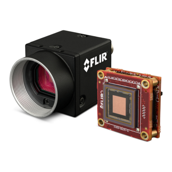
Page 20: Blackfly S Physical Interface
9. Camera label 4. General purpose I/O connector Contains camera information such as General Purpose Input/Output (GPIO) model name, serial number and required compliance. 2/14/2023 ® Teledyne FLIR Blackfly S Installation Guide ©2015-2023 FLIR Integrated Imaging Solutions Inc. All rights reserved. -
Page 21: Blackfly S Board-Level Physical Description
General Purpose Input/Output (GPIO) Status LED (to right of FPC connector) Status Indicator LED FPC connector Interface Connector Mounting holes See Mounting your Blackfly S 2/14/2023 ® Teledyne FLIR Blackfly S Installation Guide ©2015-2023 FLIR Integrated Imaging Solutions Inc. All rights reserved. -
Page 22: Blackfly S Dimensions
11.8 (C-mount) / BFS-PGE-23S3 BFS-PGE-122S6 11.8 6.8 (CS-mount) BFS-PGE-31S4 11.8 BFS-PGE-123S6 11.8 BFS-PGE-51S5 11.8 BFS-PGE-200S6 11.8 BFS-PGE-50S5 11.8 Blackfly S GigE Dimensional Drawing—Standard Format 2/14/2023 ® Teledyne FLIR Blackfly S Installation Guide ©2015-2023 FLIR Integrated Imaging Solutions Inc. All rights reserved. - Page 23 6 Blackfly S Physical Interface Model Barrel Length "A" BFS-PGE-16S7 BFS-PGE-19S4 BFS-PGE-27S5 BFS-PGE-50S4 BFS-PGE-70S7 BFS-PGE-80S5 BFS-PGE-120S6 BFS-PGE-161S7 BFS-PGE-200S7 BFS-PGE-244S8 Blackfly S GigE Dimensional Drawing—Large Format 2/14/2023 ® Teledyne FLIR Blackfly S Installation Guide ©2015-2023 FLIR Integrated Imaging Solutions Inc. All rights reserved.
- Page 24 11.8 BFS-U3-120S4 6.7 (CS-mount) BFS-U3-31S4 11.8 BFS-U3-122S6 11.8 BFS-U3-32S4 11.8 BFS-U3-123S6 11.8 BFS-U3-50S5 11.8 BFS-U3-200S6 11.8 BFS-U3-51S5 11.8 Blackfly S USB3 Dimensional Drawing—Standard Format 2/14/2023 ® Teledyne FLIR Blackfly S Installation Guide ©2015-2023 FLIR Integrated Imaging Solutions Inc. All rights reserved.
- Page 25 Barrel Length "A" Model Barrel Length "A" BFS-U3-16S7 BFS-U3-70S7 BFS-U3-17S7 BFS-U3-80S5 BFS-U3-19S4 BFS-U3-120S6 BFS-U3-20S4 BFS-U3-161S7 BFS-U3-27S5 BFS-U3-200S7 BFS-U3-28S5 BFS-U3-244S8 BFS-U3-50S4 Blackfly S USB3 Dimensional Drawing—Large Format 2/14/2023 ® Teledyne FLIR Blackfly S Installation Guide ©2015-2023 FLIR Integrated Imaging Solutions Inc. All rights reserved.
-
Page 26: Keepout Layer-Board-Level Models
Areas marked in orange (front, back, and middle) are locations where components can change or move, potentially affecting hardware integration as board revisions occur. 2/14/2023 ® Teledyne FLIR Blackfly S Installation Guide ©2015-2023 FLIR Integrated Imaging Solutions Inc. All rights reserved. -
Page 27: Interface Connector
For more detailed information, consult the USB 3.1 specification available from http://www.usb.org/developers/docs/. USB 3.1 Micro B Connector USB 3.1 Micro-B Connector Pin Assignments Signal Name Description VBUS Power 2/14/2023 ® Teledyne FLIR Blackfly S Installation Guide ©2015-2023 FLIR Integrated Imaging Solutions Inc. All rights reserved. - Page 28 Note: When the camera is connected to a USB 2.0 interface, it runs at USB 2.0 speed, and maximum frame rates are adjusted accordingly based on current imaging parameters. 2/14/2023 ® Teledyne FLIR Blackfly S Installation Guide ©2015-2023 FLIR Integrated Imaging Solutions Inc. All rights reserved.
-
Page 29: Interface Cables
For GigE cameras—Category 5e or 6 cables up to 100 meters in length should be used for connecting the camera to the network interface card on the host system. Teledyne FLIR sells a 5-meter Category 5e cable for this purpose. Note: For optimal ESD protection, we recommend using a shielded Ethernet cable or connecting the camera housing to chassis ground (earth). -
Page 30: General Purpose Input/Output (Gpio)
For USB3 cameras—In order to achieve the maximum benefits of USB3, the camera must connect to a USB3 PCIe 2.0 card. The card must be connected to the PC power supply in order to power the camera through the USB3 interface. To purchase a compatible card from Teledyne FLIR, visit the Products Accessories page. -
Page 31: Camera Temperature And Heat Dissipation
For cased models, this is expected behavior and will not damage the camera electronics. For board-level models, the temperature must be kept under 100°C and therefore may require a heat sink to avoid damage. 2/14/2023 ® Teledyne FLIR Blackfly S Installation Guide ©2015-2023 FLIR Integrated Imaging Solutions Inc. All rights reserved. -
Page 32: Lens Mounting
Mainboard Read Device_Temperature Node 6.10 Lens Mounting Lenses are not included with cameras. Teledyne FLIR sells a number of lenses compatible with our cameras from website. There is also a Lens Calculator to help choose an appropriate lens. In addition, lens mounts are not included with the board-level model cameras. Teledyne FLIR offers compatible lens... -
Page 33: Back Flange Distance-Cased Models
(assuming non-collimated light) and the possibility of damage to the sensor during cleaning is reduced. 2/14/2023 ® Teledyne FLIR Blackfly S Installation Guide ©2015-2023 FLIR Integrated Imaging Solutions Inc. All rights reserved. - Page 34 Related Knowledge Base Articles Removing the IR filter from a color camera Selecting a lens for your camera 2/14/2023 ® Teledyne FLIR Blackfly S Installation Guide ©2015-2023 FLIR Integrated Imaging Solutions Inc. All rights reserved.
-
Page 35: Infrared Cut-Off Filters-Cased Models
Schott B270 Schott B270 15.5 ±0.08 x 18 14 ±0.08 x 14 Dimensions ±0.08 mm ±0.08 mm Thickness 1 ±0.07 mm 1 ±0.07 mm 2/14/2023 ® Teledyne FLIR Blackfly S Installation Guide ©2015-2023 FLIR Integrated Imaging Solutions Inc. All rights reserved. - Page 36 6 Blackfly S Physical Interface For more information, see Dust Protection—Cased Models. Related Knowledge Base Articles Removing the IR filter from a color camera 2/14/2023 ® Teledyne FLIR Blackfly S Installation Guide ©2015-2023 FLIR Integrated Imaging Solutions Inc. All rights reserved.
-
Page 37: Readout Method
Readout time for a line is equal to 1/Horizontal Line Frequency. 2/14/2023 ® Teledyne FLIR Blackfly S Installation Guide ©2015-2023 FLIR Integrated Imaging Solutions Inc. All rights reserved. - Page 38 (Any pixel) or from the start of exposure on the last line to the end of exposure on the first line (All pixels). 2/14/2023 ® Teledyne FLIR Blackfly S Installation Guide ©2015-2023 FLIR Integrated Imaging Solutions Inc. All rights reserved.
-
Page 39: Input/Output Control
Board-level models—The camera is equipped with a 6-pin GPIO connector. The connector is a JST BM06B-NSHSS-TBT (LF)(SN), the mating connector is a JST NSHR-06V-S. 2/14/2023 ® Teledyne FLIR Blackfly S Installation Guide ©2015-2023 FLIR Integrated Imaging Solutions Inc. All rights reserved. - Page 40 Measured over operating temperature range (-20˚ C to +50˚ C ambient temperature), unless otherwise noted. 1—GPIO cable assembly wire colors 2—Dual function pin 2/14/2023 ® Teledyne FLIR Blackfly S Installation Guide ©2015-2023 FLIR Integrated Imaging Solutions Inc. All rights reserved.
- Page 41 Propagation Delay µs (USB3) Output Low Current Output High Level Brown Camera Power Ground Output Voltage 3.05 3.35 Vout Camera Power Output Output Current 2/14/2023 ® Teledyne FLIR Blackfly S Installation Guide ©2015-2023 FLIR Integrated Imaging Solutions Inc. All rights reserved.
-
Page 42: Gpio Electrical Characteristics
The opto- isolated specifications listed below are applicable when power to the camera is provided through the interface and not through the GPIO. 2/14/2023 ® Teledyne FLIR Blackfly S Installation Guide ©2015-2023 FLIR Integrated Imaging Solutions Inc. All rights reserved. - Page 43 30 V 4.7 kΩ 1.4 V 1.32 V 30 V 11.08 V 5.96 mA 3.02 mA 5.08 mA Values are for reference only 2/14/2023 ® Teledyne FLIR Blackfly S Installation Guide ©2015-2023 FLIR Integrated Imaging Solutions Inc. All rights reserved.
- Page 44 12 V 2.4 kΩ 5 mA 24 V 4.7 kΩ 5.2 mA 30 V 4.7 kΩ 6.5 mA Values are for reference only 2/14/2023 ® Teledyne FLIR Blackfly S Installation Guide ©2015-2023 FLIR Integrated Imaging Solutions Inc. All rights reserved.
- Page 45 7 Input/Output Control Non-isolated input and output circuit—Cased Non-isolated input and output circuit—Board-level 2/14/2023 ® Teledyne FLIR Blackfly S Installation Guide ©2015-2023 FLIR Integrated Imaging Solutions Inc. All rights reserved.
-
Page 46: Input Timing Characteristics
Input Threshold High Voltage 4.54 V Input Threshold Low Voltage 1.26 V Cycle Rise Time 10.8 μs Cycle Fall Time 2 μs Current 4.1 mA 2/14/2023 ® Teledyne FLIR Blackfly S Installation Guide ©2015-2023 FLIR Integrated Imaging Solutions Inc. All rights reserved. - Page 47 5.6 μs 16.7 μs PDHL Typical Positive Pulse Width 12 μs 12 μs MPPW Typical Negative Pulse Width 6 μs 6 μs MNPW 2/14/2023 ® Teledyne FLIR Blackfly S Installation Guide ©2015-2023 FLIR Integrated Imaging Solutions Inc. All rights reserved.
-
Page 48: Output Timing Characteristics
3.08 mA 8.4 mA Opto Isolator Delay (High to Low) 5.3 μs 5.5 μs Opto Isolator Delay (Low to High) 12.7 μs 15.2 μs 2/14/2023 ® Teledyne FLIR Blackfly S Installation Guide ©2015-2023 FLIR Integrated Imaging Solutions Inc. All rights reserved. - Page 49 2.68 mA 3.9 mA Opto Isolator Delay (High to Low) 3.9 μs 4.1 μs Opto Isolator Delay (Low to High) 26.8 μs 25.1 μs 2/14/2023 ® Teledyne FLIR Blackfly S Installation Guide ©2015-2023 FLIR Integrated Imaging Solutions Inc. All rights reserved.
-
Page 50: Troubleshooting
8 Troubleshooting Troubleshooting Support Teledyne FLIR endeavors to provide the highest level of technical support possible to you. Most support resources can be accessed through your product's Support page. Blackfly S USB3 Support Articles Blackfly S USB3 Resources Blackfly S GigE Support Articles Blackfly S GigE Resources... -
Page 51: Status Indicator Led
Acquisition Started Acquisition Started Rapid Flashing Green Firmware update in progress Firmware update in progress Flashing Green and Red General Error General Error 2/14/2023 ® Teledyne FLIR Blackfly S Installation Guide ©2015-2023 FLIR Integrated Imaging Solutions Inc. All rights reserved. -
Page 52: Contacting Us
For any questions, concerns or comments please contact us via the following methods: Email General questions Support Ticket Technical support Find specifications, support articles, downloads on the Website product page at Teledyne FLIR machine vision Revision History Version Date Description June 23, 2016 Support for BFS-U3-13Y3 and BFS-U3-51S5 Support for BFS-U3-32S4 and BFS-PGE-50S5... - Page 53 Support for BFS-PGE-50S4, BFS-U3-50S4, and BFS-PGE-244S8 23.0 September 9, 2021 Support for BFS-PGE-123S6P Support for BFS-PGE-120S6 and BFS-PGE-200S7 24.0 December 10, 2021 Rebranded to Teledyne FLIR Support for BFS-PGE-80S5 25.0 February 28, 2022 Added part numbers for board-level accessories 26.0 September 15, 2022 Support for BFS-U3-161S7 27.0...
Need help?
Do you have a question about the USB VISION BLACKFLY S and is the answer not in the manual?
Questions and answers