
Subscribe to Our Youtube Channel
Related Manuals for Teledyne ProEM Series


Summary of Contents for Teledyne ProEM Series
- Page 1 ® ProEM System Manual 4411-0126 Issue 3 September 26, 2019 www.princetoninstruments.com...
- Page 2 Trenton, NJ 08619 TEL: 800-874-9789 / 609-587-9797 No part of this publication may be reproduced by any means without the written permission of Teledyne Princeton Instruments. Printed in the United States of America. IntelliCal, LightField, ProEM, and PVCAM are registered trademarks of Teledyne Digital Imaging US, Inc.
-
Page 3: Table Of Contents
Table of Contents Chapter 1: About this Manual......... . . 11 Intended Audience . - Page 4 ProEM System Manual Issue 3 Chapter 4: System Setup ..........35 Unpacking the System .
- Page 5 Issue 3 Table of Contents Chapter 6: Advanced Topics ......... . . 89 Frame Transfer/Full Frame Timing {Trigger Response} Modes and Shutter Control {Shutter Mode} .
- Page 6 ProEM System Manual Issue 3 8.11 Ethernet Network is Not Accessible ........131 8.12 Program Error Message .
- Page 7 Issue 3 List of Figures List of Figures Figure 2-1: Typical ProEM System Components ......17 Figure 2-2: Typical ProEM Camera .
- Page 8 ProEM System Manual Issue 3 Figure 6-4: Flowchart: Continuous Cleans {Clean Until Trigger} ....92 Figure 6-5: Timing Diagram: WinX/32 Continuous Cleans ....93 Figure 6-6: Timing Diagram: LightField Clean Until Trigger (CUT).
- Page 9 Issue 3 List of Tables Figure B-4: Outline Drawing: ProEM Power Supply ......144 Figure B-5: Outline Drawing: CoolCUBE .
- Page 10 ProEM System Manual Issue 3 This page is intentionally blank.
-
Page 11: Chapter 1: About This Manual
ProEM Camera System Data Sheet Teledyne Princeton Instruments maintains updated documentation and user manuals on their FTP site. Visit the Teledyne Princeton Instruments FTP Site to verify that the most recent user manual is available and being referenced: ftp://ftp.piacton.com/Public/Manuals/Princeton Instruments... -
Page 12: Document Organization
Appendix B, Outline Drawings This appendix provides outline drawings of the ProEM system. • Appendix C, Spectrograph Adapters This appendix includes instructions for mounting a ProEM to a Teledyne Acton Research spectrograph adapter. • Appendix D, WinSpec/32/LightField Cross Reference This appendix includes two alphabetically sorted tables that cross reference terms used by WinX/32 and LightField. -
Page 13: Conventions Used In This Document
Chapter 1 About this Manual 1.3.1 Conventions Used In this Document WinX/32 is a generic term for WinSpec/32, WinView/32, and WinXTest/32 application software. Often WinX/32 and LightField use different terms for the same functions or parameters. When a topic pertains to both WinX/32 and LightField, curly brackets { } are used to denote a LightField term or location. -
Page 14: Proem Safety Information
WARNINGS! If the ProEM camera system is used in a manner not specified by Teledyne Princeton Instruments, the protection provided by the equipment may be impaired. 2. If the equipment or the wall outlet is damaged, the protective grounding could be disconnected. -
Page 15: Precautions
5. Do not block air vents on the camera. Preventing the free flow of air overheats the camera and may damage it. 6. If the ProEM camera system is used in a manner not specified by Teledyne Princeton Instruments, the protection provided by the equipment may be impaired. 1.6.1... - Page 16 ProEM System Manual Issue 3 This page is intentionally blank.
-
Page 17: Chapter 2: Proem Camera System
Chapter 2: ProEM Camera System This chapter provides an introduction to, and overview information about, Teledyne Princeton Instruments’s ProEM camera system. System Components A typical ProEM EMCCD camera system consists of the camera head with built-in ® shutter, a power supply with power cable , and an Intel PRO/1000 GigE card for your computer, a Gigabit Ethernet cable, MCX to BNC adapter cables, and coolant hoses. -
Page 18: Proem Camera
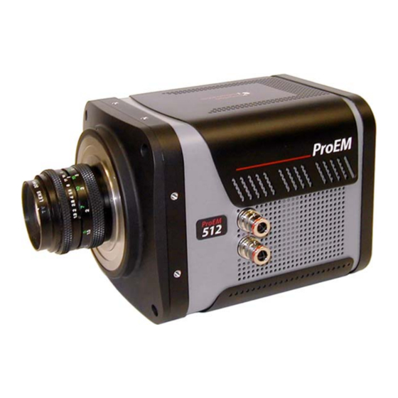
ProEM System Manual Issue 3 ProEM Camera The ProEM camera systems are the most advanced EMCCD cameras available on the market today, utilizing the latest low-noise read out electronics and back-illuminated EMCCDs to deliver single photon sensitivity. The all metal, hermetic vacuum seals used in the ProEM cameras are warrantied for life, the only such guarantee in the industry. -
Page 19: Ccd Arrays
The ProEM:1600 and ProEM:1600 feature back-illuminated full frame spectroscopy EMCCDs with the benefit of eXcelon technology. These cameras incorporate an internal manual shutter and have 3.60 inch and 3.88 inch bolt circles for mounting Teledyne Acton Research spectrograph adapters. -
Page 20: Emccd Technology And On-Chip Multiplication Gain
As the on-chip multiplication introduces additional noise, it is recommended that the multiplication be used only as required. For more information, refer to the On-Chip Multiplication Gain technical note. This technical note can be accessed by going to the Teledyne Princeton Instruments web site: www.princetoninstruments.com. 2.2.2 Cooling Dark current is reduced in ProEM camera systems through thermoelectric cooling of the CCD arrays. -
Page 21: Fan
2.2.3 eXcelon eXcelon is a CCD/EMCCD sensor technology jointly developed by Teledyne Princeton ® Instruments, Teledyne e2v, and Teledyne Photometrics . Imaging CCDs using this technology provide three significant benefits: •... -
Page 22: Connectors
Shutter ® LEMO connector provides the shutter drive pulses for driving a Teledyne Princeton Instruments-supplied 25 mm external shutter. Camera power must be off before connecting to or disconnecting from this connector. NOTE: When there is an installed internal shutter, this connector cannot drive an external shutter. -
Page 23: Coolant Ports
The coolant circulator can be any commercially available circulator that is capable of continuously pumping a 50:50 mixture of room temperature (23°C) water and ethylene glycol at 1 liter per minute, or the Teledyne Princeton Instruments CoolCUBE . Contact the factory for recommendations. Refer to... -
Page 24: Hoses
Refer to the coolant circulator's specifications regarding circulator-compatible hose fittings. If a Teledyne Princeton Instruments CoolCUBE circulator is ordered with the camera, hoses are supplied with appropriate connectors on both ends. -
Page 25: Certificate Of Performance
Certificate of Performance Each ProEM camera is shipped with a Certificate of Performance which states that the camera system has been assembled and tested according to approved Teledyne Princeton Instruments procedures. It documents the camera’s performance data as measured during the testing of the ProEM and lists the following camera- and customer-specific information: •... -
Page 26: Accessories
Issue 3 • PICam The standard 64-bit software interface for cooled CCD cameras from Teledyne Princeton Instruments. PICam is an ANSI C library of camera control and data acquisition functions. Refer to the PICam Programmer’s Manual for the list of supported operating systems. -
Page 27: C- To Spectroscopy-Mount Adapter
Chapter 2 ProEM Camera System 2.8.2 C- to Spectroscopy-Mount Adapter A C-mount to Spectroscopy-mount adapter can be ordered separately. 4411-0126_0010 2.8.3 Adjustable C- to Spectroscopy-Mount Adapter An adjustable C- to Spectroscopy-mount adapter can be ordered separately. 4411-0126_0011... -
Page 28: Unpack The System
When unpacking the system, examine the system components for any signs of shipping damage. If there are any, notify Teledyne Princeton Instruments immediately and file a claim with the carrier. Be sure to save the shipping carton for inspection by the carrier. -
Page 29: 2.10 Proem Camera And System Maintenance
160 for complete information. 2.10.3 Repairs Because the ProEM camera system contains no user-serviceable parts, repairs must be performed by Teledyne Princeton Instruments. Should the system need repair, contact Teledyne Princeton Instruments customer support for instructions. Refer to Contact Information on page 160 for complete information. - Page 30 ProEM System Manual Issue 3 This page is intentionally blank.
-
Page 31: Chapter 3: Installation Overview
Chapter 3: Installation Overview Table 3-1 lists the sequence of actions required to install a ProEM system and prepare to gather data. Refer to the indicated references for additional information. Refer to Section 3.1, System Block Diagrams, on page 32 for high-level block diagrams of typical system configurations. -
Page 32: System Block Diagrams
ProEM System Manual Issue 3 Table 3-1: ProEM Installation Actions (Sheet 2 of 2) Action Refer to… 12. Set the target array temperature. Section 5.3.4, CCD Temperature, on page 72 13. When the system reaches temperature lock, wait an Acquiring Data on page 55 additional 20 minutes and then begin acquiring data in focus mode. -
Page 33: Figure 3-2: Block Diagram: Typical Spectroscopy Experiment With
Chapter 3 Installation Overview Figure 3-2: Block Diagram: Typical Spectroscopy Experiment with Air-Cooled ProEM Figure 3-3: Block Diagram: Typical Imaging Experiment with Air/Liquid-Cooled ProEM... -
Page 34: Figure 3-4: Block Diagram: Typical Spectroscopy Experiment With
ProEM System Manual Issue 3 Figure 3-4: Block Diagram: Typical Spectroscopy Experiment with Air/Liquid-Cooled ProEM... -
Page 35: System Setup
During the unpacking, check the system components for possible signs of shipping damage. If there are any, notify Teledyne Princeton Instruments and file a claim with the carrier. If damage is not apparent but camera or controller specifications cannot be achieved, internal damage may have occurred in shipment. -
Page 36: Checking The Equipment And Parts Inventory
A complete system consists of: • Camera • Power Supply • Host Computer: Can be purchased from Teledyne Princeton Instruments or provided by user. For enhanced performance, a fast hard drive (10,000 rpm) and 2GB RAM is recommended. • Operating System: ®... -
Page 37: Power
Chapter 4 System Setup 4.3.3 Power • Camera The ProEM camera receives its power from the supplied power supply, which in turn plugs into a source of AC power. • Power Supply The receptacle on the power supply should be compatible with the line-voltage line cords in common use in the region to which the system is shipped. -
Page 38: Lightfield Requirements
ProEM System Manual Issue 3 4.3.4.2 LightField Requirements • Windows Vista (64-bit) or Windows 7 (64-bit) • 2 GHz dual core processor • 4 GB RAM (or greater) • CD-ROM drive • Super VGA monitor and graphics card supporting at least 65535 colors with at least 128 MB of memory. -
Page 39: Mounting The Lens
Chapter 4 System Setup 4.4.1 Mounting the Lens C mount lenses simply screw into the front of these cameras. Tighten the lens by hand only. NOTE: C-mount cameras are shipped with a dust cover lens installed. Although this lens is capable of providing surprisingly good images, its throughput is low and the image quality is not as good as can be obtained with a high-quality camera lens. -
Page 40: Mounting The Adjustable C- To Spectroscopy-Mount Adapter
The adjustable C- to spectrograph-mount adapter allows you to move the camera vertically at the exit plane of a Teledyne Acton Research Series spectrograph in order to align the kinetics rows at the middle of the focal plane for the best spectral quality. The adapter is mounted to the front of a ProEM camera and is secured to the camera by a threaded insert screwed into the camera’s C mount opening. -
Page 41: Figure 4-2: Typical Adjustable C- To Spectroscopy-Mount Adapter
Chapter 4 System Setup Procedure Perform the following procedure to mount the Adjustable C- to Spectroscopy-Mount adapter: If a light baffle is mounted to the front of the adapter, remove the two 2-56 screws securing it and set the baffle aside. 2. -
Page 42: Positioning The Proem:512Bk Masks
ProEM System Manual Issue 3 4.5.1 Positioning the ProEM:512BK Masks The ProEM:512BK camera has a kinetics nose that provides built-in precision masking capability and manual shutter adjustment. After using the pull-push sliders to coarsely set the position of the top and bottom masks, you can then use the micro-adjust screws while viewing images being acquired by the application software to fine tune the masking. -
Page 43: Making The Camera-Circulator Connections For A Coolcube Ii
Chapter 4 System Setup Making the Camera-Circulator Connections for a CoolCUBE For liquid-cooled cameras, the CoolCUBE circulator provides a vibration-free method of heat removal. Perform the following procedure to connect the ProEM to a CoolCUBE Make sure the camera and the circulator power switches are turned off. 2. -
Page 44: Figure 4-6: Coolcube Ii With Reservoir Cap Removed
ProEM System Manual Issue 3 Figure 4-6: CoolCUBE with Reservoir Cap Removed If additional coolant is required, fill with a 50:50 mixture of water and ethylene glycol. 6. Screw the reservoir cap back in. 7. Plug the circulator into a 100-240 V , 50-60 Hz power source. -
Page 45: Software Installation
Chapter 4 System Setup Software Installation 4.8.1 WinX/32 NOTE: Install the GigE Adapter card BEFORE installing the WinX application software. Leave the interface cable disconnected from the camera until you have installed WinX/32 (Ver. 2.5.25 or later). The following installation is performed via the WinX/32 software installation CD. Insert the CD and follow the installation wizard prompts. -
Page 46: Lightfield
ProEM System Manual Issue 3 4.8.2 LightField NOTE: Install the GigE Adapter card BEFORE installing the LightField application software. The following installation is performed via the LightField software installation CD. Before starting the installation: • Verify that the computer operating system is Windows Vista (64-bit) or Windows 7 (64-bit). -
Page 47: Entering The Default Camera System Parameters
Make sure the ProEM is connected to the host computer and that it is turned on. 2. Run the WinX/32 application. The Camera Detection wizard will automatically run if this is the first time you have installed a Teledyne Princeton Instruments WinX application (WinView/32, WinSpec/32, or WinXTest/32) and a supported camera. -
Page 48: Figure 4-10: Typical Winx/32 Controller/Camera Tab
ProEM System Manual Issue 3 Figure 4-10: Typical WinX/32 Controller/Camera Tab ELECT RAME RANSFER NOTE: For a step-by-step procedure on basic system operation (Imaging and Spectroscopy), refer to the appropriate First Light sections: • Section 5.1.1, Imaging Applications, on page 52; •... -
Page 49: Lightfield
Chapter 4 System Setup 4.9.2 LightField Make sure the ProEM (and spectrograph, if this is a spectroscopy system) is connected to the host computer and that the camera (and spectrograph) power supply is turned on. 2. Start LightField. 3. While LightField is starting up, it will detect the available device(s) and load the appropriate icons into the Available Devices area in the Experiment workspace. - Page 50 ProEM System Manual Issue 3 This page is intentionally blank.
-
Page 51: Operation
Chapter 5: Operation Once the ProEM camera has been installed as explained in the preceding chapters, operation of the camera is straightforward. In most applications you simply establish optimum performance using the Focus {Preview} mode (in WinX, for example), set the target camera temperature, wait until the temperature has stabilized, and then do actual data acquisition in the Acquire mode. -
Page 52: Winx First Light Instructions
ProEM System Manual Issue 3 Briefly: • In Focus {Preview} mode, the number of frames is ignored. A single frame is acquired and displayed, another frame is acquired and overwrites the currently displayed data, and so on until Stop is selected. In WinX, the last frame acquired before Stop is selected can be stored;... -
Page 53: Figure 5-2: Typical Winx/32 Controller/Camera Tab
Chapter 5 Operation Setting the Parameters NOTE: The following procedure is based on WinView/32: you will need to modify it if you are using a different application. Basic familiarity with the WinView/32 software is assumed. If this is not the case, you may want to review the software manual or have it available while performing this procedure. -
Page 54: Figure 5-3: Typical Winx/32 Detector Temperature Dialog
ProEM System Manual Issue 3 ► • Detector Temperature (Setup Detector Temperature…) The default temperature setting is read from the camera. When the array temperature reaches the set temperature, the Detector Temperature dialog will report that the temperature is LOCKED. Note that some overshoot may occur. This could cause temperature lock to be briefly lost and then quickly re-established. -
Page 55: Figure 5-4: Typical Winx/32 Experiment Setup Timing Tab
Chapter 5 Operation ► Figure 5-4: Typical WinX/32 Experiment Setup Timing Tab ELECT Acquiring Data If you are using WinView/32 and the computer monitor for focusing, select Focus from the Acquisition menu. Successive images will be sent to the monitor as quickly as they are acquired. -
Page 56: Spectroscopy Applications
An underlying assumption for the procedure is that the camera is to be operated with a spectrograph (such as a Teledyne Acton Research Series 2300 spectrograph) on which it has been properly installed. Refer to... -
Page 57: Figure 5-5: Typical Winx/32 Controller/Camera Tab
Chapter 5 Operation Setting the Parameters NOTE: The following procedure is based on WinSpec/32: you will need to modify it if you are using a different application. Basic familiarity with the WinSpec/32 software is assumed. If this is not the case, you may want to review the software manual or have it available while performing this procedure. -
Page 58: Figure 5-6: Typical Winx/32 Detector Temperature Dialog
ProEM System Manual Issue 3 ► • Detector Temperature (Setup Detector Temperature…) The default temperature setting is read from the camera. When the array temperature reaches the set temperature, the Detector Temperature dialog will report that the temperature is LOCKED. Note that some overshoot may occur. This could cause temperature lock to be briefly lost and then quickly re-established. -
Page 59: Figure 5-7: Typical Winx/32 Experiment Setup Timing Tab
The following procedure, which describes the focusing operation with a Teledyne Acton Research SP-2356 spectrograph, can be easily adapted to other spectrographs. - Page 60 Note that the way focusing is accomplished depends on the spectrograph, as follows: • Long focal-length spectrographs For example, the Teledyne Acton Research SP-2356. The mounting adapter includes a tube that slides inside another tube to move the camera in or out as required to achieve optimum focus. •...
-
Page 61: Lightfield First Light Instructions
Chapter 5 Operation LightField First Light Instructions 5.2.1 Imaging Applications This section provides step-by-step instructions for acquiring an imaging measurement in LightField for the first time. The intent of this procedure is to help you gain basic familiarity with the operation of your system and to show that it is functioning properly. Once basic familiarity has been established, then operation with other operating configurations, ones with more complex timing modes, can be performed. -
Page 62: Figure 5-8: Typical Lightfield Available Devices Area
ProEM System Manual Issue 3 Figure 5-8: Typical LightField Available Devices Area 2. Drag the icon into the Experiment Devices area. See Figure 5-9. Figure 5-9: Typical LightField Experiment Devices Area... -
Page 63: Figure 5-10: Typical Lightfield View Area
Chapter 5 Operation 3. Note that the Experiment Settings stack on the left now displays several expanders. Because this is a new experiment, the default settings for the camera will be active. The Status bar (at the bottom of the window) displays icons for temperature status and orientation. -
Page 64: Figure 5-11: Typical Lightfield View Area Displaying An Image
ProEM System Manual Issue 3 Figure 5-11: Typical LightField View Area Displaying an Image 3. Adjust the lens aperture, intensity scaling, and focus for the best image as viewed on the computer monitor. Some imaging tips follow: • Begin with the lens blocked off and then set the lens at the smallest possible aperture (largest f-stop number). -
Page 65: Spectroscopy Applications
An underlying assumption for the procedure is that the camera is to be operated with a spectrograph (such as a Teledyne Acton Research Series 2300 spectrograph) on which it has been properly installed. Refer to... -
Page 66: Figure 5-12: Typical Lightfield Available Devices Area
ProEM System Manual Issue 3 Figure 5-12: Typical LightField Available Devices Area 8. Drag the icons into the Experiment Devices area. See Figure 5-13. Figure 5-13: Typical LightField Experiment Devices Area... -
Page 67: Figure 5-14: Typical Lightfield View Area
The following procedure, which describes the focusing operation with a Teledyne Acton Research SP-2356 spectrograph, can be easily adapted to other spectrographs. -
Page 68: Figure 5-15: Typical Lightfield Align Spectrometer View: Pre-Adjustment
ProEM System Manual Issue 3 3. Open the Spectrometer expander, select the grating and set the center wavelength to 435.8 nm if using a mercury lamp or to 0.0 nm if using a broadband source. NOTE: Overhead fluorescent lights produce a mercury spectrum. Use a white card tilted at 45 degrees in front of the entrance slit to reflect overhead light into the spectrograph. -
Page 69: Figure 5-16: Typical Lightfield Align Spectrometer View: Post-Adjustment
Chapter 5 Operation 7. Slowly move the camera in and out of focus. You should see the spectral line go from broad to narrow and back to broad. Leave the camera set for the narrowest achievable line. Note that the Peak Finding function is active for the center graph to allow you to monitor the FWHM information to achieve the narrowest line width. -
Page 70: Exposure And Signal
ProEM System Manual Issue 3 Exposure and Signal 5.3.1 Exposure Time ► Exposure Time, which is set on the Experiment Setup Main tab {Common Acquisition Settings expander}, is the time between commands sent by the application software to start and stop signal accumulation on the sensor. In combination with triggers, these commands control when continuous cleaning of the CCD stops and when the accumulated signal will be read out. -
Page 71: Em Gain Calibration
EM gain aging while lowering effective dynamic range. For more information, refer to the On-Chip Multiplication Gain technical note. This technical note can be accessed by going to the Teledyne Princeton Instruments web site at and searching for that www.princetoninstruments.com title. -
Page 72: Ccd Temperature
ProEM System Manual Issue 3 5.3.4 CCD Temperature As stated before, lowering the temperature of the CCD will generally enhance the quality of the acquired signal by lowering dark noise. In EMCCD cameras, lower temperatures will also result in higher EM gain. •... -
Page 73: Bias Active Stabilization Engine (Base)
Chapter 5 Operation 5.3.6 Bias Active Stabilization Engine (BASE) All CCDs and EMCCDs produce a baseline output signal even when there is no incident light and the exposure is zero. Camera electronics process this information to produce what is known as a bias image. For quantitative applications, it is critical that the bias reference values be above zero. -
Page 74: Saturation
CAUTION! If you observe a sudden change in the baseline signal, there may be excessive humidity in the camera vacuum enclosure. Turn off the camera and contact Teledyne Princeton Instruments Customer Support. Refer to Contact Information on page 160 for complete information. -
Page 75: Cleaning
Chapter 5 Operation 5.3.9 Cleaning The basic cleaning function is implemented by clean cycles. These cycles start when you turn the camera on and a clean pattern is programmed into the camera. Their purpose is to remove charge that accumulates on the array while the camera not acquiring data (i.e., exposing and reading out the array). -
Page 76: Readout
ProEM System Manual Issue 3 • Clean Before Exposure {Clean Before Exposure} is only provided for cameras that have a Frame Transfer CCD and is only available for selection when in Full Frame mode is active. Normally, cleaning occurs until the acquisition starts. When Clean Before Exposure is active, cleaning occurs up until acquisition starts and the entire CCD will be cleaned once right after the readout occurs. -
Page 77: Dual-Readout Port Operation
Chapter 5 Operation The ProEM:1600 and ProEM:1600 models use full frame CCDs with 1600 x 200 and 1600 x 400 active pixels, respectively. NOTE: Typically there are additional rows and columns for internal reference. In standard frame transfer mode, the sensor area is exposed for certain time and the acquired image data are then transferred to frame transfer area before reading the data out via the multiplication gain register or standard serial register. -
Page 78: Controller Gain {Analog Gain
ProEM System Manual Issue 3 • Port #2: Low Noise (Normal CCD) When the camera is using this amplifier, electrons (signal) generated in pixels are clocked through the standard serial register. The amplifier is designed to take advantage of the dynamic range of the CCD and is most useful when the frame rate is not critical. -
Page 79: Readout Rate
Chapter 5 Operation 5.4.3 Readout Rate Refer to Table 5-3 for the list of Readout Rate supported by ProEM Table 5-3: Readout Rates Multiplication Gain CCD Type Low Noise {Electron Multiplied} Frame Transfer 5 MHz 100 kHz 10 MHz 1 MHz 5 MHz Full Frame 1 MHz... - Page 80 ProEM System Manual Issue 3 • In LightField, when ROIs are used to acquire data, the ROI parameter information for ALL of the ROIs is stored in the data file when the data are saved to disk. You can review this information for the active data display by using the Show File Information functionality (accessible from the Data Options menu in the Comparison Viewer.) NOTE:...
-
Page 81: Binning
Chapter 5 Operation 5.4.5 Binning Binning (combining pixels into one super pixel) allows you to increase the sensitivity and frame rate. On the other hand, binning reduces spatial resolution. ProEM supports flexible vertical binning and binning of 2x-32x in the horizontal. When binning in WinX, keep in mind that the resulting number of super pixels in the horizontal must be evenly divisible by 4. -
Page 82: Exposure - Readout Modes
ProEM System Manual Issue 3 5.4.6 Exposure – Readout Modes The frame transfer CCDs used by the ProEM:512B/BK and 1024B support Frame Transfer, Full Frame (sequential), Kinetics, and Spectra-Kinetics readout modes. If you are planning to use Frame Transfer mode, be aware that the set exposure time may not be the effective exposure time. -
Page 83: Figure 5-20: Timing Diagram: Frame Transfer Mode, Exposure Time
Chapter 5 Operation Figure 5-20. Figure 5-20: Timing Diagram: Frame Transfer Mode, Exposure Time < Readout Time T = 100 ms EXPOSE Exp #1 Exp #2 Exp #3 (Effective) 10 ms 30 ms 30 ms EXPOSE (Program’d) IMAGE SHIFT Readout #1 Readout #2 Readout #3 READ OUT... -
Page 84: Figure 5-21: Timing Diagram For Frame Transfer Mode When
ProEM System Manual Issue 3 Example 2: Frame Transfer Mode when Exposure Time > Readout Time If the exposure time is set to 50 ms with the readout time remaining at 30 ms, the time taken to acquire 3 frames will be 180 ms (3 x 50 ms + 30 ms), which is equivalent to a frame rate of 16.67 fps. -
Page 85: Full Frame (Sequential) Mode For Frame-Transfer Emccd
Chapter 5 Operation 5.4.6.2 Full Frame (Sequential) Mode for Frame-Transfer EMCCD Full Frame mode allows you to expose the array for the exposure time specified in the software and is similar in performance to a normal, full-frame CCD device. The operational sequence for this mode is: Clearing the CCD. -
Page 86: Full Frame Readout For Full Frame Emccd
ProEM System Manual Issue 3 Example: Full Frame Mode for Frame-Transfer EMCCD Operation in Full Frame mode is illustrated in the timing diagram below. In this example, the exposure time is 10 ms and the readout time is 30 ms. The total time to take 3 frames is 120 ms [(3 x 10 ms) + (3 x 30 ms)], equivalent to a frame rate of 25 fps (3 frames ÷... -
Page 87: Readout Time
Chapter 5 Operation Figure 5-24: Full Frame at Full Resolution Readout of the CCD begins with the simultaneous shifting of all pixels one row toward the shift register, in this case the row on the top. The shift register is a single line of pixels along the edge of the EMCCD, not sensitive to light and used for readout only. - Page 88 ProEM System Manual Issue 3 This page is intentionally blank.
-
Page 89: Advanced Topics
Chapter 6: Advanced Topics Previous chapters have discussed setting up the hardware and the software for basic operation. This chapter discusses topics associated with experiment synchronization. ► Synchronization, is configured on the Experiment Setup Timing tab in WinX/32 and on the Shutter and Trigger expanders in LightField. •... -
Page 90: Ext Sync Trigger Input
ProEM System Manual Issue 3 6.1.1 EXT SYNC Trigger Input The selected Timing Mode {Trigger Response} determines how the camera will respond to an External Sync pulse that is input at the EXT SYNC connector on the rear of the camera. -
Page 91: Free Run {No Response
Chapter 6 Advanced Topics 6.1.2 Free Run {No Response} In this mode, there is no external triggering {or the camera is ignoring external triggers} and all settings are read from the setup parameters, making the duration of each exposure time constant and the interval times between exposures constant. See Figure 6-2. -
Page 92: External Sync With Continuous Cleans {Clean Until Trigger
ProEM System Manual Issue 3 6.1.4 External Sync with Continuous Cleans {Clean Until Trigger} Timing Another timing mode available with the ProEM is called Continuous Cleans {Clean Until Trigger}. In addition to the standard cleaning of the array, which occurs after the camera is enabled, this mode will remove any charge from the array until the moment the External Sync pulse is received. -
Page 93: Bulb Trigger {Expose During Trigger Pulse} Timing
Chapter 6 Advanced Topics Figure 6-5: Timing Diagram: WinX/32 Continuous Cleans Open Close Open Close Open Close Shutter (Normal) Open Close Open Close Open Close Shutter (Preopen) Read Out Read Read Read External Sync (positive polarity shown) Figure 6-6: Timing Diagram: LightField Clean Until Trigger (CUT) Shutter Timing Mode (Normal) Open... -
Page 94: Trigger Start {Start On Single Trigger
ProEM System Manual Issue 3 In Kinetics mode-Multiple Trigger {Shift Per Trigger}, the first exposure is the same as described above. The subsequent exposures really start when WFT on the LOGIC OUT connector goes high. The External Sync on the EXT SYNC connector must then transition to the active state. -
Page 95: Fast And Safe Modes
Chapter 6 Advanced Topics Fast and Safe Modes The ProEM has been designed to allow the greatest possible flexibility when synchronizing data collection with an experiment. The fundamental difference between the Fast and Safe modes is how often the acquisition start and acquisition stop commands are sent by the computer for a data collection sequence. -
Page 96: Figure 6-8: Flowcharts Of Safe And Fast Mode Operation
ProEM System Manual Issue 3 Figure 6-8: Flowcharts of Safe and Fast Mode Operation Safe Mode Fast Mode Start Start Computer programs Computer programs camera with exposure camera with exposure and binning parameters and binning parameters Start acquisition Start acquisition command sent from command sent from computer to camera... -
Page 97: Logic Out Control
Chapter 6 Advanced Topics LOGIC OUT Control The TTL-compatible logic level output (0 to +3.3 V) from the LOGIC OUT connector on the rear panel can be used to monitor camera status and control external devices. By default, the logic output level is high while the action is occurring. The timing of the level changes depends on the output type selected on the Hardware ►... -
Page 98: Kinetics Mode
ProEM System Manual Issue 3 • Wait for Trigger {Waiting For Trigger} This level is at a logic high when the camera is ready to acquire and is waiting for an external trigger (through the EXT SYNC connector) before exposing the CCD. -
Page 99: Kinetics Readout
Chapter 6 Advanced Topics Figure 6-11: Typical LightField Sensor Expander: Kinetics Readout Mode 6.4.1 Kinetics Readout Kinetics readout allows a burst of subframes to be captured with microsecond resolution. This is accomplished by shifting each subframe exposure under the mask before reading it out. -
Page 100: Figure 6-12: Kinetics Mode: Partial Ccd Illumination, Proem:512B
ProEM System Manual Issue 3 Figure 6-12: Kinetics Mode: Partial CCD Illumination, ProEM:512B Multiplication Gain For high speed, low light level applications Serial Registers Low Noise For standard, high dynamic range applications Frame-transfer Area Frame-transfer Area 1048 Rows including reference rows Masked Masked... -
Page 101: Kinetics Timing Modes And Shutter Control
Chapter 6 Advanced Topics 6.4.2 Kinetics Timing Modes and Shutter Control For Kinetics, the timing modes are Free Run {No Response}, Single Trigger {Readout Per Trigger}, and Multiple Trigger {Shift Per Trigger}. Free run {No Response} mode is used for experiments that do not require any synchronization with the experiments. The other two modes (i.e., Single Trigger and Multiple Trigger,) require that an external TTL pulse be applied to the camera via the Trigger In connector on the I/O cable. -
Page 102: Figure 6-14: Timing Diagram: Kinetics Mode, Multiple Trigger {Shift Per
ProEM System Manual Issue 3 In multiple trigger {Shift Per Trigger} mode, each exposure-shift cycle is triggered independently by a pulse applied at the Ext Sync connector. This mode is useful when each subframe needs to be synchronized with a pulsed external light source such as a laser. -
Page 103: Cleaning The Ccd
Chapter 6 Advanced Topics Figure 6-16: Typical LightField Shutter and Trigger Expanders 6.4.4 Cleaning the CCD Since kinetics is most often used in asynchronous, single-shot experiments, it is important that CCD be cleared of accumulating background or dark charge while it is waiting for an external trigger. -
Page 104: Configuring Software Parameters In Winx/32
ProEM System Manual Issue 3 This procedure assumes: • You have already set up your system in accordance with the instructions in the previous chapters. • You have read the previous sections of this chapter. • You are familiar with the application software. •... -
Page 105: Configuring Software Parameters In Lightfield
Chapter 6 Advanced Topics 6.4.5.2 Configuring Software Parameters in LightField: NOTE: The following procedure is based on LightField. You will need to modify it if you are using a different application. Basic familiarity with the LightField software is assumed. If this is not the case, you may want to review the software manual or have it available while performing this procedure. -
Page 106: Spectra-Kinetics (Option)
ProEM System Manual Issue 3 Spectra-Kinetics (Option) Spectra-Kinetics, which is standard on the ProEM:512BK, is a software option available for purchase for use with ProEM:512B and ProEM:1024B cameras. When this option is available you will be able to select Spectra-Kinetics as the readout mode. Refer to Table 6-1 for a comparison of specifications. -
Page 107: Figure 6-18: Proem:512Bk Emccd
Chapter 6 Advanced Topics Figure 6-18: ProEM:512BK EMCCD Multiplication Gain For high speed, low light level applications Low Noise For standard, high dynamic range applications Frame-transfer Area: 528 Rows Sensor Area: 410 Rows Masked Area: 98 Rows Sensor Area: 2 Rows Figure 6-19: Example of Masking for Spectra-Kinetics: 20 Rows Exposed Frame-Transfer Mask Exposed Sensor Area: 20 Rows... -
Page 108: Summary
ProEM System Manual Issue 3 6.5.1 Summary Spectra-Kinetics is a powerful feature that allows a burst of subframes to be captured with microsecond time resolution. However, careful attention must be paid to the optical and timing considerations: • The rows closest to the serial register need to be illuminated. As can be seen in Figure 58, these rows are immediately below the frame transfer area. -
Page 109: Figure 6-20: Functional Block Diagram: Ccd Array
Chapter 6 Advanced Topics Figure 6-20: Functional Block Diagram: CCD Array Frame-transfer Area Active Area External (custom) mask for “Custom chip” readout The following example compares the time savings achieved by using Custom Chip {Custom Sensor} vs. ROI to read out a 128 x 128 region of a 512 x 512 array. Using the ROI method to read out the 128 x 128 pixels would take 8.2 ms, or a frame rate of 122 fps (1/0.0082). -
Page 110: Software Settings
Issue 3 6.6.1.1 Software Settings CAUTION! Teledyne Princeton Instruments does not encourage users to change these parameter settings. For most applications, the default settings will give the best results. We strongly advise contacting the factory for guidance before customizing the chip definition. -
Page 111: Figure 6-23: Typical Lightfield Custom Sensor Pane
Chapter 6 Advanced Topics In LightField, the Custom Sensor pane, illustrated in Figure 6-23, is accessed by opening the Sensor expander and clicking on the Custom Sensor button. Figure 6-23: Typical LightField Custom Sensor Pane By changing the values in the Active fields, you can increase image acquisition speed by reducing the size of the active area in the definition. -
Page 112: Custom Timing
ProEM System Manual Issue 3 6.6.2 Custom Timing NOTE: This mode is standard with LightField for a ProEM full frame EMCCD camera such as the ProEM:1600 In LightField, Custom Timing is accessed via the Custom Sensor button on the Sensor expander. -
Page 113: Figure 6-25: Typical Winx/32 Hardware Setup Controller/Camera Tab
Chapter 6 Advanced Topics Figure 6-25: Typical WinX/32 Hardware Setup Controller/Camera Tab: Vertical Shift... - Page 114 ProEM System Manual Issue 3 This page is intentionally blank.
-
Page 115: Chapter 7: Tips
1% and sometimes even to 0.5%. All Teledyne Princeton Instruments cameras, including the ProEM, are designed with a single window made of high-grade fused silica/quartz that acts as a vacuum view port. -
Page 116: Reduce Spectral Readout Time By Using The Custom Chip/Timing
And, unlike both Binning and ROI, Custom Chip also relies on array masking to ensure that no light falls outside the currently set active area. To take full advantage of the outstanding speed offered by Teledyne Princeton Instruments ProEM:1600 cameras for spectral data acquisition, users need to utilize the Custom Chip {Custom Sensor} and Custom Timing modes via Teledyne Princeton Instruments WinX or LightField software. -
Page 117: Winx/32 Step-By-Step Procedure
Chapter 7 Tips 7.3.2 WinX/32 Step-by-Step Procedure The following procedure uses a ProEM:1600 camera. This same procedure can be used to increase the spectral readout rate for a ProEM:1600 NOTE: The Readout Times you get may differ from those reported in this procedure. -
Page 118: Figure 7-3: Typical Winx/32 Readout Time Dialog
ProEM System Manual Issue 3 5. Select Readout Time from the Acquisition menu. The readout time is reported on the Readout Time dialog as 2.08 ms. See Figure 7-3. Figure 7-3: Typical WinX/32 Readout Time Dialog: 2.08 msec ► 6. Now go to the Hardware Setup Controller/Camera tab. -
Page 119: Figure 7-5: Typical Winx/32 Readout Time Dialog
Chapter 7 Tips 10. Select Readout Time from the Acquisition menu. The readout time is reported on the Readout Time dialog as 0.88 ms. See Figure 7-5. Figure 7-5: Typical WinX/32 Readout Time Dialog: 0.88 msec ► 11. To further reduce the readout time, open the Hardware Setup Camera/ Controller ►... -
Page 120: Lightfield Step-By-Step Procedure
ProEM System Manual Issue 3 12. Acquire a spectrum. 13. Select Readout Time from the Acquisition menu. The readout time is reported on the Readout Time dialog as 0.47 ms. NOTE: Entering 0 for the Pre- and Post-Dummies and skipping the serial register clean means that there will be some spectral artifacts in the data. -
Page 121: Procedure
Chapter 7 Tips 7.3.3.2 Procedure: Check the Readout Time (on the Readout expander) and the Frames Per Second (reported in the upper right corner of the Experiment workspace). Based on the camera default settings, the Readout Time is 2.640 s and FPS is ~0.373. 2. - Page 122 ProEM System Manual Issue 3 Figure 7-8: LightField Settings...
-
Page 123: Troubleshooting
Chapter 8: Troubleshooting WARNING! Do not attach or remove any cables while the camera system is powered on. Refer to Table 8-1 for issues which have recommended troubleshooting procedures in this chapter. Table 8-1: List of Recommended Troubleshooting Procedures Information Issue begins on…... -
Page 124: Acquisition Started But Data Display Is Empty
ProEM System Manual Issue 3 Acquisition Started but Data Display is Empty If you have started a data acquisition but no data are appearing in the data display, stop the acquisition. Look at the Data Display title bar and verify that the first number in the Region of Interest (ROI) is evenly divisible by 4. -
Page 125: Acquisition Started But Viewer Contents Do Not Update
A change in the baseline signal is normal if the temperature, gain, or speed setting has been changed. If this occurs when none of these settings have been changed, there may be excessive humidity in the camera vacuum enclosure. Turn off the camera and contact Teledyne Princeton Instruments Customer Support. Refer to Contact Information... -
Page 126: Camera Not Found
If the camera is found, select it, click on the Next button, and continue the wizard. • If the camera is still not detected, click on Cancel and contact Teledyne Princeton Instruments Customer Support. Refer to Contact Information page 160 for complete information. -
Page 127: Camera1 (Or Similar Name) In Camera Name Field
Chapter 8 Troubleshooting Camera1 (or similar name) in Camera Name field Figure 8-4: Camera1 in Camera Name Field When the Camera Detection Wizard installs a new camera, the camera is automatically named Camera# (where # = 1, 2, or 3, depending on the number of cameras detected.) This name will appear in the Hardware Setup title bar and as the active camera on the ►... -
Page 128: Cooling Troubleshooting
ProEM System Manual Issue 3 Cooling Troubleshooting 8.7.1 Temperature Lock Cannot be Achieved or Maintained. Possible causes for not being able to achieve or maintain lock could include: • Ambient temperature greater than +20°C. This condition affects TE cooled cameras. If ambient is greater than +20°C, you will need to cool the camera environment or raise the set temperature. -
Page 129: Data Overrun Due To Hardware Conflict Message
Chapter 8 Troubleshooting Data Overrun Due to Hardware Conflict message Figure 8-5: Data Overrun Due to Hardware Conflict dialog If this dialog appears when you try to acquire a test image, acquire data, or run in focus mode, check the CCD array size and then check the DMA buffer size. A large array (for example, a 2048 x 2048 array), requires a larger DMA buffer larger setting than that for a smaller array (for example, a 512 x 512 array). -
Page 130: Device Is Not Found
GigE interface, UDP ports 20200-20202 may need to be opened. These ports must be open before WinX/32 or LightField can detect a Teledyne Princeton Instruments GigE camera, but they may have been closed as part of your computer security (such as an anti-virus program or a firewall). -
Page 131: 8.10 Device Is Occupied
8.11 Ethernet Network is Not Accessible When the Teledyne Princeton Instruments software is installed, all Intel Pro/1000 interface card drivers found on the host computer are updated with the Intel Pro/1000 Grabber Adapter (Vision High-Performance IP Device) driver provided by Pleora Technologies, Inc. -
Page 132: 8.12 Program Error Message
ProEM System Manual Issue 3 Figure 8-8: Typical eBUS Driver Installation Tool Dialog 4. After making the selection, click on Install. 5. After the installation you will be asked to reboot the computer. You can: • Click on "Yes" to initiate the reboot. •... -
Page 133: 8.13 Serial Violations Have Occurred. Check Interface Cable
• The TEC Fault LED will come on if there is problem with the cooling system. Contact Teledyne Princeton Instruments Customer Service. Refer to Contact Information... -
Page 134: Winx/32 Or Lightfield Crashes When Adding Gige Camera To System
ProEM System Manual Issue 3 8.16 WinX/32 or LightField Crashes When Adding GigE Camera to System If you have a dual port Intel Pro/1000 Ethernet card and WinX/32 or LightField crashes when trying to add a GigE camera to the system, you will need to modify the default IP address for one of the ports. -
Page 135: Figure 8-13: Typical Device Pop-Up Menu
Chapter 8 Troubleshooting 4. Click on that label to expand it and then right-click on one of the ports. On the popup menu, click on Properties. See Figure 8-13. Figure 8-13: Typical Device Pop-Up Menu 5. On the Settings tab, change the third number from the left in the IP Address. For example, replace the 2 in the IP Address 192.168.2.1 with 4 so the IP Address becomes 192.168.4.1. - Page 136 ProEM System Manual Issue 3 This page is intentionally blank.
-
Page 137: Appendix A: Technical Specifications
Instruments website (www.princetoninstruments.com). Window UV grade fused-silica (0.125"/ 3.18 mm thick). Teledyne Princeton Instruments offers a choice of multi-layer VIS-AR, UV-AR, and NIR-AR coating options on the vacuum window. For enhanced sensitivity in the UV region, proprietary Unichrome™ coating of the CCD is available. -
Page 138: Mounts
The arrays listed and the specifications provided are those that were available at the time that the manual was written. For current arrays and specifications, refer to ProEM data sheets which can be downloaded from the Teledyne Princeton Instruments website (www.princetoninstruments.com). -
Page 139: Figure A-1: Rear Of Proem Camera
— Shutter: LEMO connector provides the shutter drive pulses for driving a Teledyne Princeton Instruments-supplied 25 mm external shutter in lieu of integrated shutter. Camera power must be OFF before connecting to or disconnecting from this connector. Cable not supplied. -
Page 140: Options
Scientific Imaging ToolKit™ (SITK™) for LabVIEW, C-mount to spectroscopy mount adapter, adjustable C- to spectroscopy-mount adapter, and the CoolCUBE coolant circulator. Contact Teledyne Princeton Instruments Customer Service for more information regarding options available for your system. Refer to Contact Information... -
Page 141: Appendix B: Outline Drawings
Appendix B: Outline Drawings NOTE: All dimensions are in inches [mm]. Figure B-1: Outline Drawing: ProEM:512B-1024B Camera, Standard Mount... -
Page 142: Figure B-2: Outline Drawing: Proem:512Bk - Kinetics
ProEM System Manual Issue 3 Figure B-2: Outline Drawing: ProEM:512BK - Kinetics... -
Page 143: Figure B-3: Outline Drawing: Proem:1600 Series, Full Frame Spectroscopy
Appendix B Outline Drawings Figure B-3: Outline Drawing: ProEM:1600 Series, Full Frame Spectroscopy... -
Page 144: Figure B-4: Outline Drawing: Proem Power Supply
ProEM System Manual Issue 3 Figure B-4: Outline Drawing: ProEM Power Supply 9.82 2.15 4.29... - Page 145 Appendix B Outline Drawings Figure B-5: Outline Drawing: CoolCUBE...
- Page 146 ProEM System Manual Issue 3 This page is intentionally blank.
-
Page 147: Appendix C: Spectrograph Adapters
C-mount lenses. Cameras for spectroscopy applications are designed with two different bolt circle patterns to accommodate Teledyne Acton Research sliding tubes. Before mounting your camera to a Teledyne Acton Research Series spectrograph, you should follow the instructions in this appendix for attaching the appropriate spectrograph kit and sliding tube. -
Page 148: Proem:1600 Series With 3.60"/3.88" Bolt Circles
ProEM System Manual Issue 3 ProEM:1600 Series with 3.60"/3.88" Bolt Circles Sliding Tube (Tube and plate supplied with spectrometer) Counterbored Spacer Plate Hole Item Description 2826-0584 Screw, 10-32 x 9/16", Pan Head Phillips, Stainless Steel C.1.1 Assembly Instructions Verify the shipping cover has been removed from the spectrograph’s camera port. 2. -
Page 149: C- To Spectroscopy-Mount Adapter
Appendix C Spectrograph Adapters C- to Spectroscopy-Mount Adapter Sliding Tube (supplied with spectrometer) Spacer Plate (Removed) Item Description 8401-071-01 Adapter Plate 8401-071-02 Threaded C-Mount Adapter 2826-0127 Screw, 10-32 x ¼ Button Head Allen Hex, Stainless Steel C.2.1 Assembly Instructions Verify the shipping cover has been removed from the spectrograph’s camera port. 2. -
Page 150: Adjustable C- To Spectroscopy-Mount Adapter
ProEM System Manual Issue 3 Adjustable C- to Spectroscopy-Mount Adapter (7050-0104 for SP2350/SP-2550) Item Description Adapter Plate 2518-1284 1.25"-32 Threaded Insert Assembly Instructions Verify the shipping cover has been removed from the spectrograph’s camera port. 2. Place the flat side of the adapter plate against the face of the camera. 3. -
Page 151: Adjustable C- To Spectroscopy-Mount Adapter
Appendix C Spectrograph Adapters Adjustable C- to Spectroscopy-Mount Adapter (7050-0107 for SP2150/SP-2750) Item Description Adapter Plate 2518-1284 1.25"-32 Threaded Insert C.4.1 Assembly Instructions Verify the shipping cover has been removed from the spectrograph’s camera port. 2. Place the flat side of the adapter plate against the face of the camera. 3. - Page 152 ProEM System Manual Issue 3 This page is intentionally blank.
-
Page 153: Appendix D: Winspec/32/Lightfield Cross Reference
Appendix D: WinSpec/32/LightField Cross Reference This appendix provides cross reference information for terminology used within the WinSpec/32 and LightField application software packages. WinSpec/32-to-LightField Terminology Refer to Table D-1 for a list of WinSpec/32 terms and their corresponding LightField terms. Table D-1: WinSpec/32-to-LightField Cross Reference (Sheet 1 of 2) WinSpec/32 Term LightField Term Active Rows Parallel to Shift Register... - Page 154 ProEM System Manual Issue 3 Table D-1: WinSpec/32-to-LightField Cross Reference (Sheet 2 of 2) WinSpec/32 Term LightField Term Logic Out: Shutter Output Signal: Shutter Open Minimum Block Size Final Section Height Normal Shutter Normal (Shutter) Number of Blocks Final Section Count Number of Cleans Number of Clean Cycles Number of Strips per Clean...
-
Page 155: Lightfield To Winspec/32
Appendix D WinSpec/32/LightField Cross Reference LightField to WinSpec/32 Refer to Table D-2 for a list of LightField terms and their corresponding WinSpec/32 terms. Table D-2: LightField-to-WinSpec/32 Cross Reference (Sheet 1 of 2) LightField Term WinSpec/32 Term Active Area: Bottom Margin Post-Dummy Rows Parallel to Shift Register Active Area: Left Margin Pre-Dummy Shift Register Columns... - Page 156 ProEM System Manual Issue 3 Table D-2: LightField-to-WinSpec/32 Cross Reference (Sheet 2 of 2) LightField Term WinSpec/32 Term Preview Focus Quality Readout Port Readout Per Trigger External Sync Readout Per Trigger (DIF) Single Trigger (DIF) Sensor Readout Region expander functions Easy Bin Shift Per Trigger (DIF) Dual Trigger Mode (DIF)
-
Page 157: Warranty And Service
(1) year after shipment. During this period, Teledyne Princeton Instruments will repair the product or, at its sole option, repair or replace any defective part without charge to you. You must deliver the entire product to the Teledyne Princeton Instruments factory or, at our option, to a factory-authorized service center. -
Page 158: Sealed Chamber Integrity Limited 12 Month Warranty
(1) year from shipment. Teledyne Princeton Instruments does not warrant that the function of the software will meet your requirements or that operation will be uninterrupted or error free. -
Page 159: Owner's Manual And Troubleshooting
3. All warranty service must be made by the Teledyne Princeton Instruments factory or, at our option, an authorized service center. 4. Before products or parts can be returned for service you must contact the Teledyne Princeton Instruments factory and receive a return authorization number (RMA.) Products or parts returned for service without a return authorization evidenced by an RMA will be sent back freight collect. -
Page 160: Contact Information
In no event shall Teledyne Princeton Instruments’ liability exceed the cost of the repair or replacement of the defective product or part. - Page 161 This page is intentionally blank.
- Page 162 info@princetoninstruments.com USA +1 877-474-2286 | France +33 (1) 60 86 03 65 | Germany +49 (0) 89 660 7793 | UK & Ireland +44 (0) 1628 472 346 Singapore +65 6408 6240 | China +86 10 659 16460 | Japan +81 (3) 5639 2741...
Need help?
Do you have a question about the ProEM Series and is the answer not in the manual?
Questions and answers