
Related Manuals for Teledyne Princeton Instruments PI-MAX 3


Summary of Contents for Teledyne Princeton Instruments PI-MAX 3
- Page 1 ® PI-MAX 3 System Manual 4411-0129 Issue 2 August 20, 2019 www.princetoninstruments.com...
- Page 2 Trenton, NJ 08619 TEL: 800-874-9789 / 609-587-9797 No part of this publication may be reproduced by any means without the written permission of Teledyne Princeton Instruments. Printed in the United States of America. Pentium is a registered trademark of Intel Corporation.
-
Page 3: Table Of Contents
Table of Contents Attention! ..........13 Alarm . - Page 4 ® PI-MAX 3 System Manual Issue 2 Chapter 5: System Setup ..........39 Unpack the System .
- Page 5 Issue 2 Table of Contents 7.14 LightField Experiment Setup ..........93 7.14.1 Common Acquisition Settings Expander .
- Page 6 ® PI-MAX 3 System Manual Issue 2 Chapter 11: WinX/32 and Dual Image Feature (DIF) ..... . . 151 11.1 Requirements .
- Page 7 Adapter Kits ............224 PI-MAX3 to Teledyne Acton Research Spectrograph Quick Start Guides ..224 Standard C-, F-, and Spectroscopy-Mount Adapters .
- Page 8 Procedure ...........231 PI-MAX3 to Teledyne Acton Research (C-Mount Adapter) ....233 PI-MAX3 to IsoPlane SCT-320 .
- Page 9 Issue 2 List of Figures Figure 7-1: Block Diagram: Signal Path in Standard PI-MAX3 System ..63 Figure 7-2: Timing Diagram: Internal Trigger Mode, Clean Cycles ... . . 65 Figure 7-3: Typical WinX/32 Hardware Setup Dialog: Phosphor Decay Delay .
- Page 10 ® PI-MAX 3 System Manual Issue 2 Figure 8-25: Timing Diagram: PI-MAX3 SyncMASTER1 as Master Clock..119 Figure 8-26: Typical Repetitive Gating Setup Dialog......120 Figure 8-27: Block Diagram: Single Shot .
- Page 11 Required Tools ..........231 Figure G-2: PI-MAX3 to Teledyne Acton Research with C-Mount Adapter ..233 Figure G-3:...
- Page 12 Adapter Kit Information ........224 Table G-1: Required Hardware: PI-MAX3 to Teledyne Acton Research with C-Mount Adapter233 Table G-2: Required Hardware: PI-MAX3 to IsoPlane SCT-320.
-
Page 13: Attention
I.I.T. switch to only after the illumination level has been lowered. If the alarm sounds continuously even after the illumination level is adequately low, shut the system down and contact Teledyne Princeton Instruments Customer Service for guidance. Refer to Contact Information on page 248 for more information. -
Page 14: Unigen™ Ii Coating
Do not scratch the image intensifier's coated surface. To remove any lint or dust, use very clean dry nitrogen with < 5 PSI pressure. If you have any questions please contact your sales contact or Teledyne Princeton Instruments Customer Service. Refer to Contact Information on page 248 for more information. -
Page 15: About This Manual
– Camera System Data Sheet Teledyne Princeton Instruments maintains updated documentation and user manuals on their FTP site. Visit the Teledyne Princeton Instruments FTP Site to verify that the most recent user manual is available and being referenced: ftp://ftp.piacton.com/Public/Manuals/Princeton Instruments... -
Page 16: Document Organization
• Chapter 2, PI-MAX3 Camera System This chapter provides an introduction to, and overview information about, Teledyne Princeton Instruments’ PI-MAX3 camera system. • Chapter 3, PI-MAX3 Image Acquisition This chapter provides a high-level overview of how PI-MAX3 acquires, transfers, and processes image data. -
Page 17: Conventions Used In This Document
Chapter 1 About this Manual • Chapter 16, Troubleshooting This chapter provides recommended troubleshooting procedures. • Appendix A, Technical Specifications This appendix provides system-level technical specifications. • Appendix B, Outline Drawings This appendix provides outline drawings for the PI-MAX3 camera, the PI-MAX3 power supply, and the CoolCUBE coolant circulator. -
Page 18: Safety Related Symbols Used In This Manual
WARNINGS! If the PI-MAX3 camera system is used in a manner not specified by Teledyne Princeton Instruments, the protection provided by the equipment may be impaired. 2. The PI-MAX3 has internal power supplies that generate hazardous (and potentially lethal) voltages. It contains no user-serviceable parts. -
Page 19: Intensifier Modes And Safety
Chapter 1 About this Manual 1.5.1 Intensifier Modes and Safety • WinX/32 Applications The Experiment Setup Main screen in WinX/32 applications allows you to select one of two intensifier modes: — Gate Mode; In Gate Mode, the photocathode is biased on only for the time that each gate pulse is applied. -
Page 20: High Intensity Light Damage
® PI-MAX 3 System Manual Issue 2 1.5.3 High Intensity Light Damage WARNING! Intensified CCD cameras such as the PI-MAX3, when biased on, can be irreparably damaged if continuously exposed to light levels higher than twice the A/D saturation level. Thus it is critical that you... -
Page 21: Pi-Max3 Camera System
Figure 2-1 shows those items that are typically included as part of a standard PI-MAX3 Camera system. Figure 2-1: Typical PI-MAX3 System Components This chapter provides an introduction to, and overview information about, Teledyne Princeton Instruments’ PI-MAX3 camera system. -
Page 22: Pi-Max3 Camera
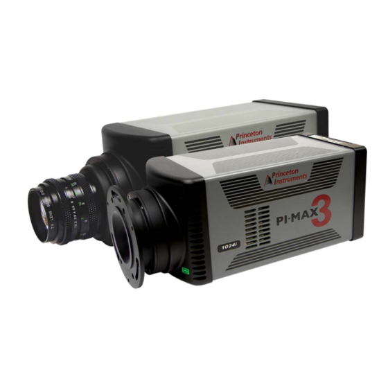
® PI-MAX 3 System Manual Issue 2 PI-MAX3 Camera The PI-MAX3 camera, illustrated in Figure 2-2, houses the CCD and intensifier and supplies all of the high voltages needed to operate the intensifier. Figure 2-2: Typical PI-MAX3 Camera The camera can be operated in one of the following two modes: •... -
Page 23: Cooling
Chapter 2 PI-MAX3 Camera System 2.1.2 Cooling Cooling within the PI-MAX3 is performed by a cooling fan and a multi-stage Peltier cooler that is thermally coupled to the CCD. A ventilation fan runs continuously to remove heat generated by the thermoelectric cooler and the electronics. -
Page 24: Pi-Max3 Rear-Panel Connectors And Indicators
® PI-MAX 3 System Manual Issue 2 2.1.5 PI-MAX3 Rear-Panel Connectors and Indicators Figure 2-3 illustrates the rear-panel connectors and indicators on a PI-MAX3 camera. CAUTION! Always turn the power off at the power supply before connecting or disconnecting any cable that interconnects the camera and the computer or serious damage to the CCD may result. -
Page 25: Table 2-1: Pi-Max3 Rear-Panel Connectors And Indicators
• OUT Either port may be used as the inlet. • IN The coolant cannot be chilled. Use the Teledyne Princeton Instruments CoolCUBE coolant circulator. For additional information, refer to: • Section 5.5, Connect PI-MAX3 to CoolCUBE , on page 45 •... -
Page 26: Power
Use of a power supply other than that provided with the PI-MAX3 camera may severely and permanently damage the camera and will void the camera warranty. For specific power supply requirements, contact Teledyne Princeton Instruments. Refer to Contact Information on page 248 for complete information. -
Page 27: Figure 2-4: Pi-Max3 Power Supply Connectors And Indicators
Chapter 2 PI-MAX3 Camera System Figure 2-4 shows the connectors and indicators found on the rear of the PI-MAX3 power supply. REFERENCES: Refer to Section A.1.2, Power Requirements, on page 204 for complete voltage specifications. Figure 2-4: PI-MAX3 Power Supply Connectors and Indicators TEC F OWER AULT... -
Page 28: Application Software
Turns the power supply ON ( ) and OFF ( To PI-MAX3 7-pin D specialty connector; connects to the PI-MAX3. Application Software Teledyne Princeton Instruments offers a number of data acquisition software packages for use with PI-MAX3 camera systems, including: ® • LightField The PI-MAX3 camera can be operated using LightField, Teledyne Princeton ®... -
Page 29: Optional Accessories
Chapter 2 PI-MAX3 Camera System Optional Accessories This section provides information about optional accessories that are available for the PI-MAX3 system. 2.3.1 Cables Table 2-3 describes the cables that may be included with a PI-MAX3 Camera System. Table 2-3: Standard PI-MAX3 Camera System Cables Part Cable Description/Purpose... -
Page 30: Coolcube Ii Coolant Circulator
® PI-MAX 3 System Manual Issue 2 2.3.2 CoolCUBE Coolant Circulator Liquid-cooled PI-MAX3 cameras can cool to a lower temperature (typically -35°C) than air cooling. Instead of using a fan to remove heat, these cameras incorporate a closed loop system of circulating fluid. The CoolCUBE circulator unit continuously pumps the 50:50 mixture of room temperature (23°C) water and ethylene glycol. -
Page 31: Flushing And Refilling The Ccd Chamber
2.4.5 Repairs Because the PI-MAX3 camera system contains no user-serviceable parts, repairs must be performed by Teledyne Princeton Instruments. Should the system need repair, contact Teledyne Princeton Instruments customer support for instructions. Refer to Contact Information on page 248 for complete information. - Page 32 ® PI-MAX 3 System Manual Issue 2 This page is intentionally blank.
-
Page 33: Pi-Max3 Image Acquisition
Chapter 3: PI-MAX3 Image Acquisition This chapter provides a high-level overview of how PI-MAX3 acquires, transfers, and processes image data. Figure 3-1 illustrates the primary components of an intensifier-CCD such as that incorporated into the PI-MAX3. Figure 3-1: Primary Components of an Intensifier-CCD Intensifier Gated On Electr on Flow... -
Page 34: Image Acquisition Process
® PI-MAX 3 System Manual Issue 2 Image Acquisition Process This section describes the process by which photons are converted to data that can be displayed on a computer monitor. NOTE: For simplicity, triggers and gate pulses are not mentioned. It is assumed that a high speed (GigE) serial interface card is installed in the host computer. -
Page 35: Installation Overview
Chapter 4: Installation Overview Table 4-1 lists the sequence of actions required to install a PI-MAX3 system and prepare to gather data. Refer to the indicated references for additional information. Refer to Section 4.1, System Block Diagrams, on page 37 for high-level block diagrams of typical system configurations. - Page 36 ® PI-MAX 3 System Manual Issue 2 Table 4-1: PI-MAX3 Installation Actions (Sheet 2 of 2) Action Refer to… 10. Turn on the host computer and launch WinX/32 or LightField. When the host computer boots, you may be asked for the location of the interface drivers.
-
Page 37: System Block Diagrams
Chapter 4 Installation Overview System Block Diagrams This section provides typical system-level block diagrams. Figure 4-1: Block Diagram: PI-MAX3 Computer Dry Nitrogen Tank GigE Trigger In Spectrograph Power 90-264 PI-MAX3 Acton SP2300i* Supply Power CoolCUBE II Supply 100-240 Coolant Circulator* * Spectrograph, coolant circulator, and dry nitrogen tank connections are optional. -
Page 38: Pi-Max
® PI-MAX 3 System Manual Issue 2 This page is intentionally blank. -
Page 39: System Setup
During unpacking, check the system components for possible signs of shipping damage. If there are any, notify Teledyne Princeton Instruments and file a claim with the carrier. Be sure to save the shipping carton for inspection by the carrier. If damage is not apparent but system specifications cannot be achieved, internal damage may have occurred in shipment. -
Page 40: Examine Equipment And Verify Parts Inventory
User-provided GigE interface card. (Intel Pro1000 recommended). • System Dependent Components: — CoolCUBE Coolant Circulator; — Coolant Tubing. If there are any problems, contact the Teledyne Princeton Instruments Customer Support. Refer to Contact Information on page 248 for complete information. -
Page 41: Mount The Pi-Max3
Chapter 5 System Setup Mount the PI-MAX3 This section provides information about mounting the PI-MAX3 for both Imaging and Spectroscopy Applications. 5.3.1 Imaging Applications The PI-MAX3 is supplied with the lens mount specified when the system was ordered. This is typically either a screw-type C-mount lens or a bayonet type F-mount lens which allows a lens of the corresponding type to be mounted quickly and easily. -
Page 42: Spectroscopy Applications
Take care not to block the ventilation openings. For additional information, refer to Section G.2, PI-MAX3 (3.60” 3-Hole Slotted Flange) to Teledyne Acton Research Series Spectrograph, on page 231. Install Application Software This section provides the procedures to install the application software. -
Page 43: Figure 5-1: Typical Winview/32 Setup Dialog: Select Installation Type
Chapter 5 System Setup Figure 5-1: Typical WinView/32 Setup Dialog: Select Installation Type 3. Click Next > to proceed with the installation. Follow all on-screen prompts. 4. Once the installation has been completed, verify the camera is connected to the host computer and that the camera power supply is turned on. -
Page 44: Install Lightfield
® PI-MAX 3 System Manual Issue 2 5.4.2 Install LightField NOTES: Install the GigE Adapter card before installing the LightField application software. 2. Verify the operating system for the host computer is 64-bit Windows Vista or 64-bit Windows 7. 3. Verify the host computer is connected to the Internet. Internet connectivity is required for product activation. -
Page 45: Connect Pi-Max3 To Coolcube Ii
Chapter 5 System Setup Connect PI-MAX3 to CoolCUBE For liquid-cooled PI-MAX3 cameras, the CoolCUBE circulator provides a vibration-free method of heat removal. Figure 5-3 illustrates a typical CoolCUBE circulator. Figure 5-3: Typical CoolCUBE Coolant Circulator Reservoir Cap Coolant Ports Perform the following procedure to connect the PI-MAX3 to the CoolCUBE Verify the camera and circulator power switches are turned off. -
Page 46: Connect Pi-Max3 To Dry Nitrogen Source
2. Launch the WinX/32 application. The Camera Detection Wizard will automatically run if this is the first time a Teledyne Princeton Instruments application has been installed (i.e., WinView/32, WinSpec/32, ore WinXTest/32,) and a supported camera is attached. Otherwise, when installing a new camera type, click on the Launch Camera... -
Page 47: Figure 5-4: Typical Camera Detection Wizard - Welcome Dialog
Chapter 5 System Setup 3. On the Camera Detection Wizard – Welcome dialog, the checkbox should remain unchecked. See Figure 5-4. Click Next >. Figure 5-4: Typical Camera Detection Wizard – Welcome Dialog 4. Follow on-screen prompts to complete the initial hardware setup. The Camera Detection Wizard automatically enters default parameter values on the Hardware Setup dialog tabs. -
Page 48: Lightfield Applications
® PI-MAX 3 System Manual Issue 2 5.7.2 LightField Applications Perform the following procedure to configure default PI-MAX3 system parameters when using LightField: Verify the PI-MAX3 and spectrograph (when using a spectroscopy system,) are connected to the host computer, and the PI-MAX3’s and spectrograph’s power supplies are turned on. -
Page 49: First Light
Required Equipment The following items are required to operate the PI-MAX3 camera system in accordance with the procedure in this section: • Teledyne Princeton Instruments PI-MAX3 camera with C-mount adapter; • PI-MAX3 power supply; • User-supplied C-mount lens with smallest aperture of f/16 or f/22;... -
Page 50: Procedure
® PI-MAX 3 System Manual Issue 2 6.1.2 Procedure This procedure assumes: • The PI-MAX3 system has been set up according to prior chapters; • Prior sections of this chapter have been read; • Familiarity with the WinX/32 software; • The PI-MAX3 camera is being operated in imaging mode;... - Page 51 This is normal and is not a cause for concern. However, if the alarm sounds continuously, even when there is no light entering the camera/spectrograph, there is something wrong. Turn off all power and contact Teledyne Princeton Instruments Customer Service for assistance. Refer to...
-
Page 52: Figure 6-2: Typical Winx/32 Supersynchro
® PI-MAX 3 System Manual Issue 2 ► 13. On the SuperSYNCHRO Trigger In tab, confirm that Internal is selected and that the Frequency is 10000 Hz. See Figure 6-2. ► Figure 6-2: Typical WinX/32 SuperSYNCHRO Trigger In Tab Dialog 14. -
Page 53: Figure 6-4: Typical Winx/32 Repetitive Gating Setup Dialog
Chapter 6 First Light 15. On the Repetitive Gating Setup dialog, configure the following parameters as indicated: • Gate Width: 50 ms; • Gate Delay: 10 ns; • Gates Per Exposure: 1; • Repeat Width/Delay for: 1. Figure 6-4. Figure 6-4: Typical WinX/32 Repetitive Gating Setup Dialog 16. -
Page 54: Figure 6-5: Typical Winx/32 Experiment Setup Main Tab Dialog
® PI-MAX 3 System Manual Issue 2 ► Figure 6-5: Typical WinX/32 Experiment Setup Main Tab Dialog 18. Click on the ADC tab to configure the Rate as indicated based on CCD type: • Kodak 1024 x 1024: 16 MHz; •... -
Page 55: Figure 6-7: Typical Winx/32 Experiment Setup
This is normal and is not a cause for concern. However, if the alarm sounds continuously, even when there is no light entering the camera/spectrograph, there is something wrong. Turn off all power and contact Teledyne Princeton Instruments Customer Service for assistance. Refer to... -
Page 56: Figure 6-8: Typical Winx/32 First Light Acquired Image
® PI-MAX 3 System Manual Issue 2 23. From the host computer, click on the ACQ button or select ► Acquisition Acquire from the WinX/32 menu bar. Data acquisition will begin and an acquired image will be displayed on the computer monitor. - Page 57 Chapter 6 First Light 25. Once it has been confirmed that PI-MAX3 is acquiring images properly, turn the PI-MAX3 I.I.T. switch to off. 26. Close the WinX/32 application. 27. If the PI-MAX3 will not be used with the lens, replace the C-mount lens with the screw-in dust cover provided with the C-mount adapter.
-
Page 58: Lightfield First Light
Required Equipment The following items are required to operate the PI-MAX3 camera system in accordance with the procedure in this section: • Teledyne Princeton Instruments PI-MAX3 camera with C-mount adapter; • PI-MAX3 power supply; • User-supplied C-mount lens with smallest aperture of f/16 or f/22;... -
Page 59: Figure 6-10: Typical Lightfield Available Devices Area
This is normal and is not a cause for concern. However, if the alarm sounds continuously, even when there is no light entering the camera/spectrograph, there is something wrong. Turn off all power and contact Teledyne Princeton Instruments Customer Service for assistance. Refer to... -
Page 60: Figure 6-11: Typical Lightfield Experiment Devices Area With Pi-Max3
® PI-MAX 3 System Manual Issue 2 11. Drag the icon representing the PI-MAX3 into the Experiment Devices area. See Figure 6-11. Figure 6-11: Typical LightField Experiment Devices Area with PI-MAX3 The Experiment Settings stack on the left now displays several expanders, including the SuperSYNCHRO Timing expander, just above the Status bar at the bottom of the workspace. -
Page 61: Figure 6-12: Typical Lightfield Online Corrections Orientation Indicator
Chapter 6 First Light 12. If the camera in use is a PI-MAX3: 1024 x 256 that was manufactured prior to January, 2012, perform these additional steps: a. Open the Online Corrections expander. b. Click on the bottom button on the Orientation image. The icon will rotate 180°. -
Page 62: Figure 6-14: Typical Lightfield View Tab With Image
® PI-MAX 3 System Manual Issue 2 16. Click on the Acquire button to start Acquire mode. See Figure 6-14. • If an image is displayed, you have confirmed that the PI-MAX3 can acquire an image; • If the image is out of focus, reposition the target and/or rotate the lens and click on Acquire to confirm that the focus has changed;... -
Page 63: Operation
Chapter 7: Operation This chapter provides general operation factors that apply to Gate Mode operation of the PI-MAX3 system. The following factors play a part before, during, and after the exposure and readout of the CCD array: • Dark Charge; •... -
Page 64: Winx/32 System On/Off Sequences
® PI-MAX 3 System Manual Issue 2 WinX/32 System On/Off Sequences The following on/off sequences are specific to WinX/32 and the Ethernet interface: • Power On Sequence The PI-MAX3 power supply must be turned on before the WinX/32 application software (WinView/32 or WinSpec/32) is opened to ensure communication between the controller and the computer. -
Page 65: Cleaning
If you observe a sudden change in the baseline signal you may have excessive humidity in the camera's CCD enclosure. Immediately turn off the controller. Contact Teledyne Princeton Instruments Customer Support for assistance. Refer to Contact Information on page 248 for complete information. - Page 66 ® PI-MAX 3 System Manual Issue 2 ► The configuration of clean cycles is performed on the Hardware Setup Cleans/Skips tab {via the Sensor Cleaning pane accessed on the Sensor expander}. When you set up the camera for the first time, default values are automatically programmed into the following parameters.
-
Page 67: Phosphor Decay Delay
Chapter 7 Operation • Skip Serial Register Clean (deselected) {Clean Serial Register} The Top margin inactive parallel strips on a CCD are made up of the dark pixels that come before the active strips on a sensor as they exit to the serial register. When these are available (i.e., Pre Dummies {Top Margin} >... -
Page 68: Temperature Control
® PI-MAX 3 System Manual Issue 2 Figure 7-3: Typical WinX/32 Hardware Setup Dialog: Phosphor Decay Delay NTER ESIRED HOSPHOR ECAY ELAY ► ► Figure 7-4: Typical LightField Common Acquisition Settings Advanced Phosphor Decay Delay Dialog Temperature Control CAUTION! Under normal conditions, the front end of the camera is sealed and backfilled so there is no danger of damage due to condensation. -
Page 69: Air-Cooling
In addition, it will be possible to achieve temperature lock at lower temperatures, typically three or four degrees lower than would be possible with air-cooling alone. Use the Teledyne Princeton Instruments CoolCUBE coolant circulator. It is a closed circulation system that depends on ambient air-cooling of the circulating coolant. -
Page 70: Setting The Temperature
® PI-MAX 3 System Manual Issue 2 7.5.2 Setting the Temperature Regardless of the type of cooling, the CCD array temperature is set via the application software. When WinX/32 is the controlling software, temperature control is done via ► the Setup Detector Temperature menu choice. -
Page 71: Saturation
Chapter 7 Operation Detection of extremely weak Continuous Wave (CW) signals (e.g., luminescence and Raman scattering from solid state samples,) is typically limited by the dark current of the intensifier's photocathode, usually referred to as the equivalent background illumination (EBI). 7.6.2 Saturation When signal levels in some part of the image are very high, charge generated in one... -
Page 72: Readout Of The Array
® PI-MAX 3 System Manual Issue 2 • Post-Processing If you prefer to acquire and preserve the raw image data, make sure that ► ► Background is not active on the Acquisition Experiment Setup… Data Corrections tab {Apply Background Subtraction box is not checked}. Then, acquire the image and save the raw image data to disk. -
Page 73: Interline Ccd Readout
Chapter 7 Operation 7.8.1 Interline CCD Readout In this section, a simple 6 x 4 pixel interline CCD is used to demonstrate how charge is shifted and digitized using a single port. See Figure 7-5. Figure 7-5: Typical Interline CCD Readout CCD Array Dual Port Readout Single Port Readout... -
Page 74: Non-Overlapped Mode Exposure And Readout
® PI-MAX 3 System Manual Issue 2 7.8.1.1 Non-Overlapped Mode Exposure and Readout Figure 7-6 illustrates exposure and readout when operating in the Non-Overlapped mode. Non-overlapped operation occurs automatically any time the exposure time is shorter than the readout time. Figure 7-6: Non-Overlapped Mode Exposure and Readout 1 Empty Readout Register. -
Page 75: Interline Readout Rate
Chapter 7 Operation • Section 3 This section represents transfer to the output node. The lowermost pixel in each column is shown empty. Each row of charges is moved in turn into the readout register, and from there to the output node and off the array for further processing. -
Page 76: Full Frame Ccd Readout
® PI-MAX 3 System Manual Issue 2 Refer to Table 7-1 for typical readout rates, in frames per second (fps,) for a PI-MAX3: 1003 Kodak 1024 x 1024 interline array running at 16 MHz. Table 7-1: Readout Rates: Kodak 1024 x 1024 Array, 16 MHz Dual Port Mode Region of Interest Size Binning 1024 x 1024... - Page 77 Chapter 7 Operation Readout of the CCD begins with the simultaneous shifting of all pixels one row toward the shift register which, in Figure 7-7, is the row on top. The shift register is a single line of pixels along the edge of the CCD, not sensitive to light and used for readout only. Typically the shift register pixels hold twice as much charge as pixels in the imaging area of the CCD.
-
Page 78: Binned Readout (Hardware Binning)
® PI-MAX 3 System Manual Issue 2 Refer to Table 7-2 for typical readout rates, in frames per second (fps,) for a PI-MAX3: e2v CCD30-11 1024 × 256 full frame array running at 2 MHz. Table 7-2: Readout Rates: e2v CCD30-11 1024 × 256 Array at 2 MHz Region of Interest Size Binning 1024 x 256... -
Page 79: Ccd Type And Readout Port(S)
Chapter 7 Operation The possibility of blooming or data loss strongly limits the number of pixels that may be binned in cases where there is a small signal superimposed on a large background, such as signals with a large fluorescence. Ideally, one would like to bin many pixels to increase the S/N ratio of the weak peaks but this cannot be done because the fluorescence would quickly saturate the CCD. -
Page 80: Figure 7-9: Typical Lightfield Roi Expander: Dual Port Readout, 2 X
® PI-MAX 3 System Manual Issue 2 Figure 7-9 illustrates the LightField Region Of Interest (ROI) expander with parameter values for Full Sensor 2 x 2 binning. Figure 7-9: Typical LightField ROI Expander: Dual Port Readout, 2 x 2 Binning, Interline CCD Figure 7-10 illustrates single port operation for a full frame array. -
Page 81: Figure 7-11: Typical Winx/32 Experiment Setup Roi Setup Tab Dialog
Chapter 7 Operation 7.8.3.1.2 WinX/32: Partial Frame ROI Binning When configuring a partial frame ROI, regardless of the array type (i.e., full frame or interline,) keep in mind that for the PI-MAX3 the following constraint applies: the number of pixels in the serial (horizontal) direction must be evenly divisible by 4, even after binning. -
Page 82: Figure 7-12: Lightfield: Edit Regions Of Interest Dialog
® PI-MAX 3 System Manual Issue 2 7.8.3.1.3 LightField: Partial Frame ROI Binning Partial Frame ROI binning can be defined via the Region of Interest expander's Custom Region(s) of Interest function and the Edit Regions of Interest window. See Figure 7-12. -
Page 83: Figure 7-13: Single Port Readout: 2 X 2 Binning, Partial Frame, Interline Ccd
Chapter 7 Operation Figure 7-13 illustrates single port operation for a partial frame with an interline CCD. Figure 7-13: Single Port Readout: 2 x 2 Binning, Partial Frame, Interline CCD Empty Readout Register. Exposure has ended Charges from two masked areas in each column have and image has been shifted to masked area been shifted to Readout Register and added. -
Page 84: Figure 7-14: Lightfield Region Of Interest Expander: Dual Port Readout
® PI-MAX 3 System Manual Issue 2 Figure 7-14: LightField Region Of Interest Expander: Dual Port Readout, 5 x 3 Binning, Interline CCD NOTE: On LightField's Region of Interest expander, you can select Full Sensor, Binned and enter Bin W and Bin H values that would not be allowed if you selected Custom Region(s) of Interest and entered them in the Edit ROIs…... -
Page 85: Software Binning
Chapter 7 Operation Software Binning Software binning is a software-averaging post-acquisition process that can be performed on either unbinned or hardware-binned data. This type of binning can improve the S/N ratio by as much as the square root of the number of binned pixels. Unfortunately, with a high number of scans (i.e., above 100,) camera 1/f noise may reduce the actual S/N ratio to slightly below this theoretical value. -
Page 86: Controller Gain {Analog Gain
® PI-MAX 3 System Manual Issue 2 7.10 Controller Gain {Analog Gain} Controller gain, which is a function of the preamplifier, is software-selectable and is used to change the relationship between the number of electrons acquired on the CCD and the Analog-to-Digital Units (ADUs or counts) generated. Three factors should be considered when configuring Controller Gain: •... -
Page 87: Logic Out Control
Chapter 7 Operation 7.12 Logic Out Control The TTL-compatible logic level output (0 to +3.3 V ) from the LOGIC OUT connector on the rear panel can be used to monitor camera status and control external devices. By default, the logic output level is high while the action is occurring. Figure 7-15 illustrates the WinX/32 dialog on which Logic Out is configured. - Page 88 ® PI-MAX 3 System Manual Issue 2 • Image Shift {Shifting Under Mask} This level is at a logic high while the image is being shifted under the mask. • Logic 1 {Always High} The level at the connector is high. •...
-
Page 89: Winx/32 Experiment Setup
Chapter 7 Operation 7.13 WinX/32 Experiment Setup This section provides information about configuring each system parameter within WinX/32. 7.13.1 Experiment Setup ► Main Tab In WinX, the first experiment setup parameters are typically configured on the ► Experiment Setup Main tab. See Figure 7-17. -
Page 90: Experiment Setup ► Timing Tab
® PI-MAX 3 System Manual Issue 2 • Intensifier Gain The Intensifier gain setting provides continuous adjustment over a range of 1 to 100. Gain is approximately proportional to the number entered. 100 is maximum gain or 100%; 1 is approximately 1% of maximum gain. The default setting will give good results in many applications. - Page 91 Chapter 7 Operation With the exception of Fast Mode/Safe Mode, which is described in full, the following paragraphs briefly describe these timing parameters. The settings appropriate to the intensifier mode and selected pulser are discussed in Chapter 8, WinX/32 and Gated Operation, on page 97.
-
Page 92: Figure 7-19: Flowcharts: Fast Mode Versus Safe Mode
® PI-MAX 3 System Manual Issue 2 Figure 7-19: Flowcharts: Fast Mode versus Safe Mode Safe Mode Fast Mode Start Start Computer programs Computer programs camera with exposure camera with exposure and binning parameters and binning parameters Start acquisition Start acquisition command sent from command sent from computer to camera... -
Page 93: Lightfield Experiment Setup
Chapter 7 Operation 7.14 LightField Experiment Setup This section provides information about configuring each system parameter within LightField. Initial experiment setup for LightField is an easy process. If your PI-MAX3 is powered on when you start LightField, the camera will be detected and its icon will be placed in the Available Devices area. -
Page 94: Region Of Interest Expander
® PI-MAX 3 System Manual Issue 2 7.14.2 Region of Interest Expander Figure 7-21 illustrates a typical LightField Region of Interest expander. Figure 7-21: Typical LightField Region of Interest Expander The Region of Interest expander allows you to specify how much of the total sensor image area will be used to acquire the data (i.e., full sensor, or one or more regions of interest.) This is also where you can set up and select either hardware or software binning. -
Page 95: Trigger Expander
Chapter 7 Operation 7.14.3 Trigger Expander Figure 7-22 illustrates a typical LightField Internal Trigger expander, while Figure 7-23 illustrates a typical LightField External Trigger expander. Figure 7-22: Typical LightField Trigger Expander: Internal Trigger Source Figure 7-23: Typical LightField Trigger Expander: External Trigger Source The Trigger expander is where you specify the trigger source (i.e., Internal or External,) to be used to trigger gating. -
Page 96: Supersynchro Expander
® PI-MAX 3 System Manual Issue 2 7.14.4 SuperSYNCHRO Expander Figure 7-24 illustrates a typical LightField SuperSYNCHRO Timing expander. Figure 7-24: Typical LightField SuperSYNCHRO Timing Expander The Super SYNCHRO Timing expander is located at the bottom of the LightField desktop. This is where you select the type of gating (i.e., Repetitive, Sequential, or DIF,) and enter the gate delay and width information. -
Page 97: Chapter 8: Winx/32 And Gated Operation
Chapter 8: WinX/32 and Gated Operation This chapter discusses gated operation with the SuperSYNCHRO™ timing generator and aspects of operation of the PI-MAX3 not covered in Chapter 6, First Light, on page 49. We additionally suggest that you review Chapter 15, Tips and Tricks, on page 183, which contains information that should prove helpful in getting good results in more complex measurements. -
Page 98: Precautionary Measures
® PI-MAX 3 System Manual Issue 2 Precautionary Measures WARNING! Intensified CCD detectors, such as the PI-MAX3, when biased ON, can be irreparably damaged if continuously exposed to light levels higher than twice the A/D saturation level. Thus it is critical that you establish conditions that... -
Page 99: Alarm
Chapter 8 WinX/32 and Gated Operation 8.1.2 Alarm NOTE: It is normal for the alarm to sound briefly when the system is turned on. To reduce the risk of detector damage, the PI-MAX3 detector is equipped with an audible alarm in the detector head, activated when the intensity of light falling on the image intensifier exceeds a preset threshold. -
Page 100: Mcp Bracket Pulsing
® PI-MAX 3 System Manual Issue 2 For this mode, the following parameters are automatically configured by the application software and cannot be changed: • Exposure Time is set to 0; • Continuous Cleans is disabled; • Shutter Control is set to Disabled Opened. Table 8-1: Timing Mode, Shutter Control, and Ext. -
Page 101: Bracket Pulsing In Lif Measurements
Chapter 8 WinX/32 and Gated Operation By bracket pulsing the MCP off (in addition to photocathode gating), the on/off ratio of the Gen II PI-MAX3 in UV is improved by 2-3 orders of magnitude. The resulting UV ratio exceeds even the high levels normally achieved in the visible. Applications that benefit from this new approach include LIF and nanosecond pump-probe experiments. -
Page 102: Limitations Of Bracket Pulse Gating
® PI-MAX 3 System Manual Issue 2 8.3.3 Limitations of Bracket Pulse Gating MCP bracket pulse gating is most useful in rejecting background that lasts microseconds up to CW. Fast transient backgrounds can be in the form of stray laser light scattering (e.g., Raleigh, MIE, or Raman,) or unwanted fast fluorescence. -
Page 103: Setup
Chapter 8 WinX/32 and Gated Operation 8.3.5 Setup MCP Bracket pulse implementation is accomplished by selecting Bracket Pulsing ON from the host software. Figure 35, is a timing diagram for bracket pulsing. Insertion delay between trigger and T0 is ~ 12 ns. Insertion delay to photocathode gate is 35 ns (i.e., the minimum delay in bracket mode is 35 ns): this delay allows the MCP to be up to full gain before the photocathode is gated on. -
Page 104: Additional Experiments
® PI-MAX 3 System Manual Issue 2 Additional Experiments Figure 8-3 illustrates the kinds of experiments that can be performed with a PI-MAX3 detector. Figure 8-3: Typical PI-MAX3 Experiments All I Experiments Gated Cooled Photocathode Photon Starved Repetitive One Shot Static Gate Swept Gate Single Shot... -
Page 105: Swept Gate Experiment [Fixed Width; Variable Delay]
Chapter 8 WinX/32 and Gated Operation • Single Shot A single shot experiment is one where you have only one chance to catch the data. Any experiment that can't be repeated more often than once a minute, such as high power lasers and explosives, is considered a single shot. You have to catch the trigger when it comes. -
Page 106: Figure 8-5: Timing Diagram: Swept Gate Experiment
® PI-MAX 3 System Manual Issue 2 Figure 8-5 illustrates the timing diagram for this experiment. Figure 8-5: Timing Diagram: Swept Gate Experiment [Fixed Width, Variable Delay] Trigger In ~12 ns Aux Out Delay is programmable. * Level changes for T0 depend on the pulse sequence(s) defined by the user. Perform the following procedure to configure this experiment: NOTE: Because this procedure uses the experiment as its Master... -
Page 107: Figure 8-7: Typical Define Spectrograph Dialog
Chapter 8 WinX/32 and Gated Operation a. Click Load Default Values on the Cleans/Skips tab. b. Configure the detector temperature by selecting Detector Temperature on the Setup menu. Entering the desired Target Temperature and click Set Temp. Finally, click OK. Refer to the WinView/32 or WinSpec/32 manual as necessary. 3. -
Page 108: Figure 8-8: Typical Install/Remove Spectrographs Dialog
® PI-MAX 3 System Manual Issue 2 Figure 8-8: Typical Install/Remove Spectrographs Dialog Figure 8-9: Typical Define Spectrograph Dialog: Main Tab [Acton SP300i]... -
Page 109: Figure 8-10: Typical Move Spectrograph Dialog
Chapter 8 WinX/32 and Gated Operation 4. After you have installed and defined the spectrograph, move the grating to the desired wavelength. See Figure 8-10. Figure 8-10: Typical Move Spectrograph Dialog 5. At this point, verify that the camera is focused by running it in Internal Trigger mode. Perform the following procedure to configure Internal Trigger mode: ►... -
Page 110: Figure 8-12: Typical Experiment Setup Dialog: Timing Tab
® PI-MAX 3 System Manual Issue 2 b. On the Timing tab, select Fast Mode. See Figure 8-12. Figure 8-12: Typical Experiment Setup Dialog: Timing Tab c. On the ADC tab, select the appropriate rate. See Figure 8-13. Figure 8-13: Typical Experiment Setup Dialog: ADC Tab... -
Page 111: Figure 8-14: Typical Experiment Setup Dialog: Roi Setup Tab
Chapter 8 WinX/32 and Gated Operation d. On the ROI Setup tab, select the appropriate ROI. See Figure 8-14. Figure 8-14: Typical Experiment Setup Dialog: ROI Setup Tab e. On the SuperSYNCHRO Trigger In tab, select Internal. See Figure 8-15. Figure 8-15: Typical SuperSYNCHRO Dialog: Trigger In Tab... -
Page 112: Figure 8-16: Typical Supersynchro Dialog: Trigger In Tab
® PI-MAX 3 System Manual Issue 2 6. After setting the parameters and making sure the ambient light level is low, click Focus. • If the readout mode is currently set to Use Region of Interest on the Main tab, the camera will start acquiring data immediately. -
Page 113: Figure 8-17: Typical Supersynchro Dialog: Gating Tab
Chapter 8 WinX/32 and Gated Operation b. On the Gating tab, select Sequential as the Active Mode and then click Setup…. If you have a Gen II intensifier, set Bracket Pulsing to OFF for this experiment. Figure 8-17. Figure 8-17: Typical SuperSYNCHRO Dialog: Gating Tab VAILABLE FOR II I NTENSIFIERS... -
Page 114: Figure 8-19: Typical Width/Delay Sequence Dialog
® PI-MAX 3 System Manual Issue 2 d. Configure the Pulse Sequence parameters as indicated: • Configure the Number of Spectra to be acquired. In this case, 41. • Under Increment Type, select Fixed Increment. • Under Gate Width, configure the desired Start and End times. NOTE: Since this experiment requires a fixed gate width these values will be the same. -
Page 115: Figure 8-20: Typical Supersynchro Dialog: Trigger Out Tab
Chapter 8 WinX/32 and Gated Operation e. The functions on the Trigger Out tab allow you to enable the SyncMASTER™ trigger output from the SyncMASTER1 and SyncMASTER2 connectors on the AUX I/O cable and configure the Aux. Out signal at the AUX OUT connector on the rear of the PI-MAX3. -
Page 116: Figure 8-21: Typical Experiment Setup Dialog: Timing Tab
® PI-MAX 3 System Manual Issue 2 9. Perform the following procedure to configure the experiment parameters on the Experiment Setup dialog. a. On the Timing tab, configure timing as shown in Figure 8-21. Figure 8-21: Typical Experiment Setup Dialog: Timing Tab 10. -
Page 117: Figure 8-22: Typical Experiment Setup Dialog: Main Tab
Chapter 8 WinX/32 and Gated Operation Figure 8-22: Typical Experiment Setup Dialog: Main Tab NOTE: The number of spectra is automatically updated/ programmed depending on the number configured on the Sequential Gating Setup dialog. See Figure 8-18. 11. After verifying all connections and equipment readiness, click Acquire to begin acquiring the spectra/images. -
Page 118: Syncmaster1 As Master Clock
® PI-MAX 3 System Manual Issue 2 Figure 8-23: Typical 3D Experiment Results 8.4.1.2 SyncMASTER1 as Master Clock When using a light source that is equipped with Trigger In, the PI-MAX3 SyncMASTER function can be used as the Master clock. Figure 8-24 illustrates the block diagram for this configuration, and... -
Page 119: Swept Gate Experiment [Variable Width, Variable Delay]
Chapter 8 WinX/32 and Gated Operation Figure 8-25: Timing Diagram: PI-MAX3 SyncMASTER1 as Master Clock Based on Internal SyncMASTER1 Out SyncMASTER1 Out Trigger Frequency Photocathode Gating Photocathode Gating Delay and Width MCP Gating MCP Gating are User-Settable AUX OUT AUX OUT T0 (on AUX I/O cable) T0 (on AUX I/O cable) T0 (on AUX I/O cable) -
Page 120: Static Gate Experiment [Fixed Width, Fixed Delay]
® PI-MAX 3 System Manual Issue 2 8.4.3 Static Gate Experiment [Fixed Width, Fixed Delay] The procedure to configure a Static Gate experiment with fixed width and delay is similar to that for a Swept Gate experiment with the following configuration changes: •... -
Page 121: Figure 8-27: Block Diagram: Single Shot
Chapter 8 WinX/32 and Gated Operation In this experiment, the cables are kept as short as possible to minimize the length of the fiber-optic cable required. Figure 8-27 illustrates the hardware block diagram for this experiment. Figure 8-27: Block Diagram: Single Shot GigE Trigger In PI-MAX3... -
Page 122: Figure 8-29: Typical Experiment Setup Dialog: Main Tab, Gain Configuration
® PI-MAX 3 System Manual Issue 2 The sequence of operations is similar to the Sequential experiments. After focusing the camera on the fluorescing sample, the camera is set in Gate mode and the appropriate Gain is selected. See Figure 8-29. -
Page 123: Figure 8-31: Single Shot Result: Fluorescence Spot, 100 Ns Width
Chapter 8 WinX/32 and Gated Operation Figure 8-31 shows the result of the experiment. Figure 8-31: Single Shot Result: Fluorescence Spot, 100 ns Width, 10 ns Delay Figure 8-32 shows the peak obtained by binning, in the vertical direction, the entire region around the fluorescence spot. - Page 124 ® PI-MAX 3 System Manual Issue 2 This page is intentionally blank.
-
Page 125: Chapter 9: Lightfield And Gated Operation
Chapter 9: LightField and Gated Operation This chapter discusses gated operation with the SuperSYNCHRO™ timing generator and aspects of operation of the PI-MAX3 not covered in Chapter 6, First Light, on page 49. We additionally suggest that you review Chapter 15, Tips and Tricks, on page 183, which contains information that should prove helpful in getting good results in more complex measurements. -
Page 126: Precautionary Measures
® PI-MAX 3 System Manual Issue 2 Precautionary Measures WARNING! Intensified CCD detectors, such as the PI-MAX3, when biased ON, can be irreparably damaged if continuously exposed to light levels higher than twice the A/D saturation level. Thus it is critical that you establish conditions that... -
Page 127: Alarm
Chapter 9 LightField and Gated Operation 9.1.2 Alarm NOTE: It is normal for the alarm to sound briefly when the system is turned on. To reduce the risk of detector damage, the PI-MAX3 detector is equipped with an audible alarm in the detector head, activated when the intensity of light falling on the image intensifier exceeds a preset threshold. -
Page 128: Mcp Bracket Pulsing
® PI-MAX 3 System Manual Issue 2 For this mode, the following parameters are automatically configured by the application software and cannot be changed: • Exposure Time is set to 0; • Continuous Cleans is disabled; • Shutter Control is set to Disabled Opened. Table 9-1: Timing Mode, Shutter Control, and Ext. -
Page 129: Bracket Pulsing In Lif Measurements
Chapter 9 LightField and Gated Operation By bracket pulsing the MCP off (in addition to photocathode gating), the on/off ratio of the Gen II PI-MAX3 in UV is improved by 2-3 orders of magnitude. The resulting UV ratio exceeds even the high levels normally achieved in the visible. Applications that benefit from this new approach include LIF and nanosecond pump-probe experiments. -
Page 130: Limitations Of Bracket Pulse Gating
® PI-MAX 3 System Manual Issue 2 9.3.3 Limitations of Bracket Pulse Gating MCP bracket pulse gating is most useful in rejecting background that lasts microseconds up to CW. Fast transient backgrounds can be in the form of stray laser light scattering (e.g., Raleigh, MIE, or Raman,) or unwanted fast fluorescence. -
Page 131: Setup
Chapter 9 LightField and Gated Operation 9.3.5 Setup MCP Bracket pulse implementation is accomplished by selecting Bracket Pulsing ON from the host software. Figure 35, is a timing diagram for bracket pulsing. Insertion delay between trigger and T0 is ~ 12 ns. Insertion delay to photocathode gate is 35 ns (i.e., the minimum delay in bracket mode is 35 ns): this delay allows the MCP to be up to full gain before the photocathode is gated on. -
Page 132: Additional Experiments
® PI-MAX 3 System Manual Issue 2 Additional Experiments Figure 9-3 illustrates the kinds of experiments that can be performed with a PI-MAX3 detector. Figure 9-3: Typical PI-MAX3 Experiments All I Experiments Gated Cooled Photocathode Photon Starved Repetitive One Shot Static Gate Swept Gate Single Shot... -
Page 133: Swept Gate Experiment [Fixed Width; Variable Delay]
Chapter 9 LightField and Gated Operation • Single Shot A single shot experiment is one where you have only one chance to catch the data. Any experiment that can't be repeated more often than once a minute, such as high power lasers and explosives, is considered a single shot. You have to catch the trigger when it comes. -
Page 134: Figure 9-5: Timing Diagram: Swept Gate Experiment
® PI-MAX 3 System Manual Issue 2 Figure 9-5 illustrates the timing diagram for this experiment. Figure 9-5: Timing Diagram: Swept Gate Experiment [Fixed Width, Variable Delay] Trigger In ~12 ns Aux Out Delay is programmable. * Level changes for T0 depend on the pulse sequence(s) defined by the user. Perform the following procedure to configure this experiment: NOTE: Because this procedure uses the experiment as its Master... -
Page 135: Figure 9-7: Typical Spectrometer Expanders
Chapter 9 LightField and Gated Operation 3. If using a Teledyne Acton Research spectrograph, verify it was turned on when LightField was launched. If using an LS-785, its icon should be in the Available Devices area. When the respective spectrograph icon is dragged into the Experiment Devices area, the Spectrometer expander is added to the Experiment Settings stack. -
Page 136: Figure 9-8: Typical Region Of Interest Expander: Full Sensor Selected
® PI-MAX 3 System Manual Issue 2 Figure 9-8: Typical Region of Interest Expander: Full Sensor Selected 6. At this point, verify that the camera is focused by running it in Internal Trigger mode. Perform the following procedure to configure Internal Trigger mode: a. -
Page 137: Figure 9-10: Typical Analog To Digital Conversion Expander
Chapter 9 LightField and Gated Operation b. On the Analog to Digital Conversion expander, select the desired Speed and Analog Gain. See Figure 9-10. Figure 9-10: Typical Analog to Digital Conversion Expander c. On the Trigger expander, select Internal. See Figure 9-11. -
Page 138: Figure 9-12: Typical Region Of Interest Expander: Full Sensor Binned
® PI-MAX 3 System Manual Issue 2 Figure 9-12: Typical Region of Interest Expander: Full Sensor Binned 10. On the Trigger expander, change Trigger Source to External, and define the external trigger parameters. See Figure 9-13. Figure 9-13: Typical Trigger Expander: External Trigger Source... -
Page 139: Figure 9-14: Typical Supersynchro Timing Expander
Chapter 9 LightField and Gated Operation 11. Perform the following procedure to configure Gate Timing: a. Open the SuperSYNCHRO Timing expander located just above the Status bar. Figure 9-14. Figure 9-14: Typical SuperSYNCHRO Timing Expander b. Select Sequential as the Active Mode. If you have a Gen II intensifier, set Bracket Pulsing to OFF for this experiment. -
Page 140: Figure 9-15: Typical Supersynchro Timing With Syncmaster On
® PI-MAX 3 System Manual Issue 2 Figure 9-15: Typical SuperSYNCHRO Timing with SyncMASTER On 12. After verifying all connections and equipment readiness, collapse the SuperSYNCHRO Timing expander. 13. If necessary, click on the View tab to view it, and click Acquire to begin acquiring the spectra (or images). -
Page 141: Syncmaster1 As Master Clock
Chapter 9 LightField and Gated Operation Figure 9-16: Typical Experiment Results with Frame Cross-Section Active 9.4.1.2 SyncMASTER1 as Master Clock When using a light source that is equipped with Trigger In, the PI-MAX3 SyncMASTER function can be used as the Master clock. Figure 9-17 illustrates the block diagram for this configuration, and... -
Page 142: Swept Gate Experiment [Variable Width, Variable Delay]
® PI-MAX 3 System Manual Issue 2 Figure 9-18: Timing Diagram: PI-MAX3 SyncMASTER1 as Master Clock Based on Internal SyncMASTER1 Out SyncMASTER1 Out Trigger Frequency Photocathode Gating Photocathode Gating Delay and Width MCP Gating MCP Gating are User-Settable AUX OUT AUX OUT T0 (on AUX I/O cable) T0 (on AUX I/O cable) -
Page 143: Static Gate Experiment [Fixed Width, Fixed Delay]
Chapter 9 LightField and Gated Operation 9.4.3 Static Gate Experiment [Fixed Width, Fixed Delay] The procedure to configure a Static Gate experiment with fixed width and delay is similar to that for a Swept Gate experiment with the following configuration changes: •... -
Page 144: Figure 9-20: Block Diagram: Single Shot
® PI-MAX 3 System Manual Issue 2 In this experiment, the cables are kept as short as possible to minimize the length of the fiber-optic cable required. Figure 9-20 illustrates the hardware block diagram for this experiment. Figure 9-20: Block Diagram: Single Shot GigE Trigger In PI-MAX3... -
Page 145: Figure 9-22: Typical Common Acquisition Settings Expander: Configure
Chapter 9 LightField and Gated Operation The sequence of operations is similar to the Sequential experiments. After focusing the camera on the fluorescing sample, the appropriate Gain is selected. See Figure 9-22. Figure 9-22: Typical Common Acquisition Settings Expander: Configure Gain Gate width and gate delay are set in such a way that the intensifier is gated ON during the entire event (in this case the event is a 60 ns fluorescence). -
Page 146: Figure 9-24: Single Shot Result: Fluorescence Spot, 100 Ns Width
® PI-MAX 3 System Manual Issue 2 Figure 9-24 shows the result of the experiment. Figure 9-24: Single Shot Result: Fluorescence Spot, 100 ns Width, 25 ns Delay Figure 9-25 shows the peak obtained by binning, in the vertical direction, the entire region around the fluorescence spot. -
Page 147: Chapter 10: Timing Generator Pulses And Sequences
Chapter 10: Timing Generator Pulses and Sequences This chapter discusses Timing Generator pulses and sequences. 10.1 Pulse Set A pulse set includes the following signals: • MCP_GATE; • START; • STOP; • AUX1; • SyncMASTER. START and STOP define the photocathode gate pulse. NOTE: MCP GATE, START, and STOP are not visible to the user and are included for information purposes only. -
Page 148: Supported Timing Generator Trigger Modes
® PI-MAX 3 System Manual Issue 2 10.1.1 Supported Timing Generator Trigger Modes PI-MAX3 supports the following Trigger Modes: • Trigger per Pulse The pulse set is initiated by its own internal or external trigger. See Figure 10-2. Figure 10-2: Timing Diagram: Trigger per Pulse TRIGGER PULSE SET PULSES... -
Page 149: Supported Timing Generator Trigger Modes
Chapter 10 Timing Generator Pulses and Sequences 10.2.1 Supported Timing Generator Trigger Modes PI-MAX3 supports the following Trigger Modes: • Trigger per Pulse Each pulse of the single sequence is initiated by its own trigger. NOTE: All triggers must originate from the same source and all must be either internal or external. -
Page 150: Pi-Max
® PI-MAX 3 System Manual Issue 2 This page is intentionally blank. -
Page 151: Chapter 11: Winx/32 And Dual Image Feature (Dif)
Chapter 11: WinX/32 and Dual Image Feature (DIF) The purpose of PI-MAX3 DIF is to acquire a pair of gated images in rapid succession. The time between frames can be as short as 2 s (limit imposed by P46 phosphor decay time) with exposure times as short as 5 ns. -
Page 152: Timing Modes
® PI-MAX 3 System Manual Issue 2 11.3 Timing Modes The following two DIF timing/readout modes are available in WinX: • Single Trigger Mode Two shot, one trigger for both shots. • Dual Trigger Mode Two shot, each shot requires a trigger. The trigger(s) can be generated by an external source connected to the PI-MAX3 or the PI-MAX3 can generate the trigger(s) internally. -
Page 153: Figure 11-3: Typical Hardware Setup Controller/Camera Tab
Chapter 11 WinX/32 and Dual Image Feature (DIF) NOTE: For the purposes of this procedure, it is assumed that either WinView/32 or WinSpec/32 is being used to control the system. Operating PI-MAX3 in DIF mode is similar to standard operation of a PI-MAX3 with SuperSYNCHRO. -
Page 154: Figure 11-4: Typical Experiment Setup
® PI-MAX 3 System Manual Issue 2 3. Configure the PI-MAX3 to Gate Mode for the intensifier to operate properly. This can be done by clicking the Gate Mode button on the Custom Toolbar, or by ► ► selecting Gate Mode on the Acquisition Experiment Setup…... -
Page 155: Figure 11-6: Typical Pulsers Dialog
Chapter 11 WinX/32 and Dual Image Feature (DIF) 5. Select Pulsers from the Setup menu, select SuperSYNCHRO, and click on the Setup Pulser button. See Figure 11-6. Figure 11-6: Typical Pulsers Dialog Perform the following procedure to configure SuperSYNCHRO: a. On the Gating tab of the SuperSYNCHRO dialog, select DIF Gating and click the Setup button. -
Page 156: Figure 11-8: Typical Dif Gating Setup Dialog
® PI-MAX 3 System Manual Issue 2 b. On the DIF Gating Setup dialog, configure the Gate Width and Gate Delay times: ≥ 75 s; • When configuring the Initial Gate Delay time, verify that it is • When configuring the Inter-Pulse Gate Delay time, verify that the delay is ►... -
Page 157: Figure 11-10:Typical Supersynchro Dialog: Trigger Out Tab
Chapter 11 WinX/32 and Dual Image Feature (DIF) d. If required, on the Trigger Out tab, configure output triggers. Figure 11-10:Typical SuperSYNCHRO Dialog: Trigger Out Tab e. At the bottom of the SuperSYNCHRO dialog, click OK to download the gating sequence to the SuperSYNCHRO. -
Page 158: Configure A Dual Trigger Dif Experiment
® PI-MAX 3 System Manual Issue 2 11.5 Configure a Dual Trigger DIF Experiment Figure 11-1 illustrates the system block diagram for a dual-trigger DIF experiment. Figure 11-11: Typical System Block Diagram: DIF Operation Computer Trigger 1 Trigger 2 100-240 GiGE Trigger In LASER 1... -
Page 159: Figure 11-13: Typical Hardware Setup Controller/Camera Tab
Chapter 11 WinX/32 and Dual Image Feature (DIF) Operating PI-MAX3 in DIF mode is similar to standard operation of a PI-MAX3 with SuperSYNCHRO. Perform the following procedure to configure a dual-trigger DIF experiment: Align and focus the PI-MAX3 on the area of interest for the experiment. This is best performed while the PI-MAX3 is operating in Interline mode (i.e., before switching to DIF mode.) Verify that the Phosphor Decay Time is appropriate for the phosphor used by the... -
Page 160: Figure 11-14:Typical Experiment Setup
® PI-MAX 3 System Manual Issue 2 3. Configure the PI-MAX3 to Gate Mode for the intensifier to operate properly. This can be done by clicking the Gate Mode button on the Custom Toolbar, or by ► ► selecting Gate Mode on the Acquisition Experiment Setup…... -
Page 161: Figure 11-16:Typical Pulsers Dialog
Chapter 11 WinX/32 and Dual Image Feature (DIF) 5. Select Pulsers from the Setup menu, select SuperSYNCHRO, and click on the Setup Pulser button. See Figure 11-6. Figure 11-16:Typical Pulsers Dialog Perform the following procedure to configure SuperSYNCHRO: a. On the Gating tab of the SuperSYNCHRO dialog, select DIF Gating and click the Setup button. -
Page 162: Figure 11-18:Typical Dif Gating Setup Dialog: Dual Trigger
® PI-MAX 3 System Manual Issue 2 b. On the DIF Gating Setup dialog, configure the Gate Width and Gate Delay times: ≥ 75 s; When configuring the Pulse 1 Gate Delay time, verify that it is Figure 11-8. Figure 11-18:Typical DIF Gating Setup Dialog: Dual Trigger c. -
Page 163: Figure 11-20:Typical Supersynchro Dialog: Trigger Out Tab
Chapter 11 WinX/32 and Dual Image Feature (DIF) d. If required, on the Trigger Out tab, configure output triggers. Figure 11-20:Typical SuperSYNCHRO Dialog: Trigger Out Tab e. At the bottom of the SuperSYNCHRO dialog, click OK to download the gating sequence to the SuperSYNCHRO. -
Page 164: Tips And Tricks
® PI-MAX 3 System Manual Issue 2 11.6 Tips and Tricks Experiments using the DIF feature of the PI-MAX3 can be complex, and timing of the events is usually rather exacting. Here are several points to consider that may make the experiment setup or troubleshooting much smoother and easier. -
Page 165: Chapter 12: Lightfield And Dual Image Feature (Dif)
Chapter 12: LightField and Dual Image Feature (DIF) The purpose of PI-MAX3 DIF is to acquire a pair of gated images in rapid succession. The time between frames can be as short as 450 ns. The second image will have some remnants from the first image due to the longer persistence of the P46 phosphor. -
Page 166: Interline Ccd Operation
® PI-MAX 3 System Manual Issue 2 Figure 12-2: Typical Common Acquisition Settings Expander Finally, it is recommended that the intensifier have a fast decay phosphor (P46). Since DIF operation involves acquiring images in rapid succession, phosphor persistence can become the limiting factor in the rate of image acquisition. NOTE: As of this writing, PI-MAX3: 1024i is the only PI-MAX3 that supports DIF mode. -
Page 167: Trigger Configuration
Chapter 12 LightField and Dual Image Feature (DIF) 12.3 Trigger Configuration Triggering for DIF operation is configured on the Trigger and the SuperSYNCHRO expanders. Trigger configuration consists of selecting the Trigger Response and the Trigger Source. Figure 12-3. Figure 12-3: Typical Trigger Expander •... -
Page 168: Configure A Single Trigger Dif Experiment
® PI-MAX 3 System Manual Issue 2 — Internal Trigger pulses will be generated by the PI-MAX3 using the Internal Trigger Frequency setting that has been configured on the SuperSYNCHRO Timing expander. See Figure 12-4. Figure 12-4: Typical SuperSYNCHRO Timing Expander: DIF The range of valid frequencies is 2 Hz to 1 MHz, in 1 Hz increments. -
Page 169: Figure 12-6: Timing Diagram: Dif Operation, Single Trigger
Chapter 12 LightField and Dual Image Feature (DIF) Figure 12-6 shows the timing diagram for single-trigger DIF operation. Figure 12-6: Timing Diagram: DIF Operation, Single Trigger FIRST FRAME SECOND FRAME Operating PI-MAX3 in DIF mode is similar to standard operation of a PI-MAX3 with SuperSYNCHRO. - Page 170 ® PI-MAX 3 System Manual Issue 2 3. On the Trigger expander: • Verify Trigger Response is configured to Readout Per Trigger. If necessary, configure this as required. • Select the desired Trigger Source: — External Verify the trigger characteristics configured on the Trigger expander match the active trigger edge, etc.
-
Page 171: Configure A Dual Trigger Dif Experiment
Chapter 12 LightField and Dual Image Feature (DIF) 12.4 Configure a Dual Trigger DIF Experiment Figure 12-7 illustrates the system block diagram for a dual-trigger DIF experiment. Figure 12-7: Typical System Block Diagram: DIF Operation Computer Trigger 1 Trigger 2 100-240 GiGE Trigger In... - Page 172 ® PI-MAX 3 System Manual Issue 2 Operating PI-MAX3 in DIF mode is similar to standard operation of a PI-MAX3 with SuperSYNCHRO. Perform the following procedure to configure a single-trigger DIF experiment: Align and focus the PI-MAX3 on the area of interest for the experiment. This is best performed while the PI-MAX3 is operating in Full Frame readout mode (i.e., before switching to DIF mode.) Verify that the Phosphor Decay Time is appropriate for the phosphor used by the...
-
Page 173: Tips And Tricks
Chapter 12 LightField and Dual Image Feature (DIF) b. Use the hyperlinks at the top of the expanded panel to make any necessary changes to the following parameter configurations: • Intensifier Settings; • Trigger Settings; • Phosphor Decay Delay Time; •... - Page 174 ® PI-MAX 3 System Manual Issue 2 This page is intentionally blank.
-
Page 175: Chapter 13: Mcp Gating
Chapter 13: MCP Gating MCP gating (not to be confused with MCP bracket pulsing) provides a unique combination of nanosecond-scale gating speed and high ultraviolet QE. Normally, such high UV QE is only available in so-called slow gate intensifiers (i.e., those without a nickel underlay.) The PI-MAX3 applies the primary gating pulse to the MCP portion of the tube and applies the bracket pulse to the photocathode. -
Page 176: Hardware Configuration For Mcp Gated Operation
® PI-MAX 3 System Manual Issue 2 13.4 Hardware Configuration for MCP Gated Operation Figure 13-1 illustrates the hardware block diagram for an MCP gated experiment using SuperSYNCHRO™. Figure 13-1: Hardware Block Diagram: MCP Gated Operation 100/240 GigE 100/240 PI-MAX3 100/240 Photodiode The laser trigger output is applied to the PI-MAX3's TRIGGER IN connector to initiate... -
Page 177: Figure 13-2: Timing Diagram: Mcp Gated Operation
Chapter 13 MCP Gating Figure 13-2: Timing Diagram: MCP Gated Operation Trigger In ~12 ns 75 - 225 ns* Gate Start Bracket Aux Out... - Page 178 ® PI-MAX 3 System Manual Issue 2 This page is intentionally blank.
-
Page 179: Chapter 14: Picosecond Option
Chapter 14: Picosecond Option The picosecond gating option for the PI-MAX3 allows optical gates down to less than 500 ps or to the lowest gate width the intensifier will support, whichever is greater. It consists of a Picosecond Gating Board installed in the PI-MAX3 and additional modifications to support the board. -
Page 180: Monitor Operation
® PI-MAX 3 System Manual Issue 2 14.3 MONITOR Operation The MONITOR output at the BNC on the rear panel is calibrated to provide a rising edge at the time the optical gate is opening (±500 ps.) The MONITOR width is NOT indicative of the optical gate width. -
Page 181: Methods For Finding A Short Optical Pulse
Chapter 14 Picosecond Option 14.6 Methods for Finding a Short Optical Pulse Method 1 The textbook method is to calculate all the delays in the optical and trigger paths and set the PI-MAX3 delay accordingly. If one does all the arithmetic correctly and has accurate numbers for all of the delays involved, this method will work. - Page 182 ® PI-MAX 3 System Manual Issue 2 2. We now set the sequential gating parameters for 20 ns gate width and 101 images/spectra {frames} at 10 ns per image/spectra {frames}. This spans the 1 s. We set the starting gate delay of 25 ns, ending gate delay of 1025, and take the sequence.
-
Page 183: Chapter 15: Tips And Tricks
15.1 Overexposure Protection WARNING! Image intensified detectors such as the PI-MAX3 can be destroyed if exposed to excessive light levels. Teledyne Princeton Instruments cannot take responsibility for damage due to misuse. ≥... -
Page 184: Time Budgets
® PI-MAX 3 System Manual Issue 2 15.2.1 Time Budgets A time budget is a listing of all the delays in the system that affect coincidence of the signal and gate at the camera. Given a system that, in addition to the PI-MAX3 and an internal timing generator, contained a low-jitter pulsed laser triggered from an external timer and an external trigger source that is also triggering the pulse generator, a time budget for this system might appear as follows. -
Page 185: Adjusting The Signal Delay
Chapter 15 Tips and Tricks The signal timing will probably be more difficult to measure. Typically, you might divert a small portion of the laser beam using a pellicle mirror located near the sample position. By directing the beam to a PIN diode module, you could obtain an electrical signal that could be monitored with the oscilloscope to accurately indicate the arrival of the laser beam at the sample position. -
Page 186: Optimizing The Gate Width And Delay
® PI-MAX 3 System Manual Issue 2 15.2.4 Optimizing the Gate Width and Delay When the basic delay questions have been answered, the next consideration is optimization of the Gate Width and Delay. The goal is to have the gate just bracket the signal event. -
Page 187: Triggered Lasers
Chapter 15 Tips and Tricks 15.3.2 Triggered Lasers • Timing Generator as Trigger Source Using the PI-MAX3's SyncMASTER1 signal to trigger the laser allows you to get rid of the propagation delay for the External Trigger (25 ns) and to set up all timing relative to T You will still need to consider the delays from: —... -
Page 188: Lens Performance
® PI-MAX 3 System Manual Issue 2 15.5 Lens Performance Imaging applications require that a lens be mounted to the detector. Because the lens characteristics affect system performance, it may be helpful to review some basic lens concepts. Basically, light from an object enters the front of the lens and is focused to a sharp image on the photocathode of the intensifier. -
Page 189: Baseline Signal
Detector Temperature dialog. Temperature lock should be re-established within a few minutes. 15.8 Intensifier Alarm CAUTION! Contact Teledyne Princeton Instruments immediately if sporadic or continuous unwarranted alarms occur. They may indicate intensifier damage or another situation that requires immediate attention. - Page 190 ® PI-MAX 3 System Manual Issue 2 This page is intentionally blank.
-
Page 191: Chapter 16: Troubleshooting
Chapter 16: Troubleshooting WARNING! Do not attach or remove any cables while the camera system is powered on. CAUTION! If a sudden change in the baseline signal is observed, there may be excessive humidity in the CCD enclosure of the camera. -
Page 192: Alarm Sounds Repetitively
An excess humidity condition should be corrected promptly or permanent damage not covered by the Warranty could occur. Have the unit serviced by Teledyne Princeton Instruments or an authorized Teledyne Princeton Instruments service facility. -
Page 193: Camera Stops Working
Chapter 16 Troubleshooting 16.5 Camera Stops Working Problems with the host computer system or software may have side effects that appear to be hardware problems. If you are sure the problem is in the camera system hardware, begin with these simple checks: Turn off all AC power. -
Page 194: Gradual Deterioration Of Cooling Capability
DMA channels. 16.9 Ethernet Network is Not Accessible When Teledyne Princeton Instruments software is installed, all Intel Pro/1000 interface card drivers found on the host computer are updated with the Intel Pro/1000 Grabber Adapter (Vision High-Performance IP Device) driver provided by Pleora Technologies, Inc. -
Page 195: Lightfield Applications
Chapter 16 Troubleshooting 3. When the program executes, select the appropriate Ethernet card. See Figure 16-1. Under the Action column, select Install Manufacturer Driver from the pull-down menu. Figure 16-1: Typical WinX/32 eBUS Driver Installation Tool Dialog 4. After making the selection, click Install. 5. -
Page 196: Excessive Readout Noise
300 ADU. If these types of spikes occur, especially after the camera has been in use for an extended period, turn off the system immediately. Have the unit serviced by Teledyne Princeton Instruments or an authorized service facility of Teledyne Princeton Instruments. -
Page 197: Appendix A: Technical Specifications
15 e @ 1 MHz digitization 35 e @ 32 MHz digitization 22 e @ 2 MHz digitization a. Contact Teledyne Princeton Instruments for P46 and P47 Phosphor availability. Dimensions Refer to Appendix B, Outline Drawings, on page 209. Gating... - Page 198 ® PI-MAX 3 System Manual Issue 2 Maximum Repetition Rate (photocathode) Sustained: 1 MHz in variable mode; 6.25 kHz with bracket Digital Conversion: 16 bits TTL Requirements ≤ Rise time: 40 ns ≥ Duration: 100 ns. Image Intensifier: 18 mm or 25 mm Method of Coupling: fiber optic Mounts Three different interchangeable mounts/adapters are available so that C-mount...
-
Page 199: Figure A-1: Typical Phosphor Emission Spectra
Poor linearity is observed when one attempts to get large signal amplitude from a single short exposure. This is a general property of MCP image intensifiers, not just of Teledyne Princeton Instruments ICCDs. Photocathode Dark Charge (EBI) Red-blue enhanced, < 5 counts/pixel-second;... - Page 200 ® PI-MAX 3 System Manual Issue 2 Spectral Range Gen II: • Red-blue enhanced, 180-900 nm; • Red enhanced, 360-920 nm Filmless Gen III: • HQ, 450-900 nm; • HQ (Blue), 375-900 nm Non-uniformity Typically: • for Gen II 18 mm intensifiers pk-pk •...
-
Page 201: Aux I/O Connector Pinout
Appendix A Technical Specifications Outputs: • READY: TTL signal. Represents camera status. It changes state when ready just before the exposure. • Gig-E: Gigabit Ethernet connector. • LOGIC OUT: 0 to +3.3V programmable logic level output (TTL-compatible). The output can be programmed via software as: —... -
Page 202: Figure A-3: Aux I/O Connector Pinout
® PI-MAX 3 System Manual Issue 2 Figure A-3 illustrates the pinout of the 26-pin AUX I/O connector. Figure A-3: AUX I/O Connector Pinout The AUX I/O (Input/Output Status) connector provides information about trigger function, DAC, and TTL signals. Inputs must be at least 2.4 V for a TTL high and less than 0.9 V for a low. - Page 203 Appendix A Technical Specifications Table A-3: AUX I/O Connector Pinout and Signal Description (Sheet 2 of 3) PIN # Signal Name and Description General Purpose Input 0 Reserved for future use as general LVCMOS input limited ESD protection. L_Shutter Via 1 k Do Not Use.
-
Page 204: Power Requirements
® PI-MAX 3 System Manual Issue 2 Table A-3: AUX I/O Connector Pinout and Signal Description (Sheet 3 of 3) PIN # Signal Name and Description NOT USED System chassis ground. Any external circuitry intended to interface with the trigger control signals must reference this ground connection. -
Page 205: Ventilation
— Filmless Gen III 18 mm: < 5 ns FWHM; • Slow Gate Intensifier — 18 mm: ~50 ns FWHM; Contact the factory or Teledyne Princeton Instruments representative. — 25 mm: ~100 ns FWHM; Contact the factory or Teledyne Princeton Instruments representative. ≤... -
Page 206: Intensifier Quantum Efficiency
® PI-MAX 3 System Manual Issue 2 Intensifier Quantum Efficiency Figure A-4 shows the Quantum Efficiency curve for selected Gen II Intensifiers. Figure A-5 shows the Quantum Efficiency curve for selected Gen III Filmless Intensifiers. Figure A-4: QE Curve: Gen II Intensifier SB Slow Gate SB Fast Gate RB Fast Gate... -
Page 207: Coolcube Ii Circulator
3 meter (2 foot) piece of ¼" ID hose joined by a reducer to a 2.4 meter (8') piece of 3/8" ID hose. Refer to your coolant circulator's specifications regarding circulator-compatible hose fittings. If a Teledyne Princeton Instruments CoolCUBE... -
Page 208: Minimum Host Computer Requirements
® PI-MAX 3 System Manual Issue 2 Minimum Host Computer Requirements NOTE: Computers and operating systems experience frequent updates. Therefore, the following sections are intended to provide minimum system requirements for operating a PI-MAX3 camera. A faster computer with 2 GB or larger memory (RAM) will greatly enhance the software performance during live mode operations. -
Page 209: Appendix B: Outline Drawings
Appendix B: Outline Drawings NOTE: Dimensions are in inches and [mm] unless otherwise noted. PI-MAX3 Figure B-1: Outline Drawing: PI-MAX3 with C-Mount Adapter... -
Page 210: Figure B-2: Outline Drawing: Pi-Max3 With F-Mount Adapter
® PI-MAX 3 System Manual Issue 2 Figure B-2: Outline Drawing: PI-MAX3 with F-Mount Adapter... -
Page 211: Figure B-3: Outline Drawing: Pi-Max3 With Spectroscopy-Mount Adapter
Appendix B Outline Drawings Figure B-3: Outline Drawing: PI-MAX3 with Spectroscopy-Mount Adapter... -
Page 212: Pi-Max3 Power Supply
® PI-MAX 3 System Manual Issue 2 PI-MAX3 Power Supply Figure B-4: Outline Drawing: PI-MAX3 Power Supply 9.82 2.15 4.29... -
Page 213: Coolcube Ii Circulator
Appendix B Outline Drawings CoolCUBE Circulator Figure B-5: Outline Drawing: CoolCUBE Circulator... - Page 214 ® PI-MAX 3 System Manual Issue 2 This page is intentionally blank.
-
Page 215: Appendix C: Winspec/32 And Lightfield Cross References
Appendix C: WinSpec/32 and LightField Cross References This appendix provides cross reference information for terminology used within the WinSpec/32 and LightField application software packages. WinSpec/32-to-LightField Terminology Refer to Table C-1 for a list of WinSpec/32 terms and their corresponding LightField terms. - Page 216 ® PI-MAX 3 System Manual Issue 2 Table C-1: WinSpec/32-to-LightField Cross Reference (Sheet 2 of 2) WinSpec/32 Term LightField Term Logic Out: Shutter Output Signal: Shutter Open Minimum Block Size Final Section Height Normal Shutter Normal (Shutter) Number of Blocks Final Section Count Number of Cleans Number of Clean Cycles...
-
Page 217: Lightfield To Winspec/32
Appendix C WinSpec/32 and LightField Cross References LightField to WinSpec/32 Refer to Table C-2 for a list of LightField terms and their corresponding WinSpec/32 terms. Table C-2: LightField-to-WinSpec/32 Cross Reference (Sheet 1 of 2) LightField Term WinSpec/32 Term Active Area: Bottom Margin Post-Dummy Rows Parallel to Shift Register Active Area: Left Margin Pre-Dummy Shift Register Columns... - Page 218 ® PI-MAX 3 System Manual Issue 2 Table C-2: LightField-to-WinSpec/32 Cross Reference (Sheet 2 of 2) LightField Term WinSpec/32 Term Preview Focus Quality Readout Port Readout Per Trigger External Sync Readout Per Trigger (DIF) Single Trigger (DIF) Sensor Readout Region expander functions Easy Bin Shift Per Trigger (DIF) Dual Trigger Mode (DIF)
-
Page 219: Appendix D: Extender Bracket Kit
Appendix D: Extender Bracket Kit An Extender Bracket kit is shipped with each PI-MAX3.After securing the bracket at the rear of the PI-MAX3, you can mount the PI-MAX3 to any laboratory table with either 25 mm or 1 inch hole spacing. Figure D-1 illustrates a typical extender bracket mounted to the PI-MAX3. - Page 220 ® PI-MAX 3 System Manual Issue 2 4. Secure the plate with the three screws. 5. Turn the camera right side up and secure it to the laboratory table. If using one or more mounting holes at the bottom front of the camera, tighten the fastener(s) there before tightening down the fastener(s) at the extender bracket.
-
Page 221: Appendix E: Mounting And Focusing C- And F-Mount Lenses
Appendix E: Mounting and Focusing C- and F-Mount Lenses This appendix provides information about the mounting and focus of C- and F-mount lenses. Lens Mounting C-mount lenses simply screw clockwise into the threaded lens mount at the front of the camera. In mounting a C-mount lens, tighten it securely by hand (no tools). To mount an F-mount lens on the camera, locate the large indicator dot on the side of the lens. -
Page 222: Mounting Orientation
® PI-MAX 3 System Manual Issue 2 E.1.1 Mounting Orientation The PI-MAX3 can be mounted at any attitude or angle. The camera can rest on any secure surface. Take care not to block the ventilation openings. CAUTION! In the case of cameras equipped with F-mount, do not mount the camera in the nose-up operation where the lens mount would be required to hold the camera's weight. -
Page 223: Appendix F: C-, F-, And Spectroscopy-Mount Adapters
F-1. Figure F-1: Screwdriver with Reversible Flat and Phillips Tips • A PI-MAX3 (with spectroscopy-mount adapter) to Teledyne Acton Research spectrograph quick start sheet. F.1.2 PI-MAX3 25 mm Tube Among the items in the accessory kit shipped with a 25 mm PI-MAX3 are: •... -
Page 224: Adapter Kits
Because each PI-MAX3 system is shipped with a spectroscopy-mount adapter kit, a quick start guide for mounting a PI-MAX3 with spectroscopy-mount adapter to a Teledyne Acton Research spectrograph is included. Typically, the guide assumes that there is a spectroscopy-mount adapter mounted to the face of the PI-MAX3 camera. -
Page 225: Spectroscopy-Mount For Nvuv Cameras
Appendix F C-, F-, and Spectroscopy- Mount Adapters Figure F-2: PI-MAX3 Mount Adapters Mounting Screws (4 Places) C-Mount Spec-Mount F-Mount 2. Remove the existing adapter and store it in a safe place. 3. Using the same screws, mount the new adapter to the front of the PI-MAX3. Spectroscopy-Mount for NVUV Cameras In addition to the spectroscopy adapter, NVUV cameras require two o-rings, each with a different inner diameters (I.D). -
Page 226: Optical Distance From Mounting Face To Image Plane
® PI-MAX 3 System Manual Issue 2 Perform the following procedure to mount an NVUV spectroscopy-mount adapter: Using the supplied screwdriver, remove the four (4) Phillips head screws that secure the current adapter to the front of the PI-MAX3. NOTE: If the Phillips end of the screwdriver is not available, pull the driver shaft out of the handle, flip the shaft, and insert the flat end into the handle. -
Page 227: Appendix G: Spectrograph Adapters
Appendix G: Spectrograph Adapters A PI-MAX3 with the spectroscopy-mount adapter can be readily mounted to a Teledyne Acton Research Series spectrograph or to an IsoPlane SCT-320 spectrograph. Mounting the camera to a Teledyne Acton Research Series spectrograph requires a male sliding tube that slides into the spectrograph for setting the focus. - Page 228 The method of focusing depends on the spectrograph, as follows. • Long focal-length spectrographs (e.g., Teledyne Acton Research SP-2300i): The mounting adapter includes a tube that slides inside another tube to move the detector in or out as required to achieve optimum focus.
-
Page 229: Isoplane Sct-320 Spectrograph
Perform the following procedure to focus a PI-MAX3 when mounted on an IsoPlane SCT-320 spectrograph: Mount a Teledyne Acton Research light source such as the dual HG/NeAr source in front of the entrance slit of the spectrograph. 2. With the spectrograph properly connected to the computer, turn the power on, wait for the spectrograph to initialize. - Page 230 ® PI-MAX 3 System Manual Issue 2 11. Next adjust the rotation. First, use a 9/64” hex wrench to loosen the four screws at the corners of the detector mounting plate. While watching a live display of the line, rotate the detector (up to 4 degrees of rotation are possible). The line will go from broad to narrow and back to broad.
-
Page 231: Pi-Max3 (3.60" 3-Hole Slotted Flange) To Teledyne Acton Research
Appendix G Spectrograph Adapters PI-MAX3 (3.60” 3-Hole Slotted Flange) to Teledyne Acton Research Series Spectrograph This section provides the installation procedure used to mount a PI-MAX3 to a Teledyne Acton Research series spectrograph. G.2.1 Required Tools Figure G-1 shows the tools required for this procedure. - Page 232 ® PI-MAX 3 System Manual Issue 2 Loosen setscrew with 3/32” hex wrench. Loosen setscrew. Gently rotate and pull. Finger tighten hex head screws. Leave about ¼” thread exposed. Mount tube to camera, align baffle with Gently rotate while inserting. bottom/top of camera, and tighten mounting screws.
-
Page 233: Pi-Max3 To Teledyne Acton Research (C-Mount Adapter)
UPPLIED WITH PECTROGRAPH PACE LATE EMOVED Table G-1 lists the required hardware to mount a PI-MAX3 to a Teledyne Acton Research spectrograph with a C-Mount Adapter. Table G-1: Required Hardware: PI-MAX3 to Teledyne Acton Research with C-Mount Adapter Item Description... - Page 234 ® PI-MAX 3 System Manual Issue 2 Perform the following procedure to mount a PI-MAX3 to a Teledyne Acton Research spectrograph with a C-Mount Adapter: Verify the shipping cover has been removed from the detector port on the spectrograph. 2. Loosen the set screws holding the sliding tube in the spectrograph and remove the tube.
-
Page 235: Pi-Max3 To Isoplane Sct-320
Appendix G Spectrograph Adapters PI-MAX3 to IsoPlane SCT-320 Figure G-3 illustrates how to mount a PI-MAX3 to an IsoPlane SCT-320. Figure G-3: PI-MAX3 to IsoPlane SCT-320 LANE OUNTING LATE Table G-1 lists the required hardware to mount a PI-MAX3 to an IsoPlane SCT-320. Table G-2: Required Hardware: PI-MAX3 to IsoPlane SCT-320. - Page 236 ® PI-MAX 3 System Manual Issue 2 This page is intentionally blank.
-
Page 237: Appendix H: Glossary
Appendix H: Glossary Binning: A process that may occur in the readout register and the output node (on-chip or hardware binning) or is performed as a post-process (software binning). Binning combines charge from rectangular groups of adjacent pixels into super pixels. When done on-chip, this process reduces readout time and the burden on computer memory;... - Page 238 ® PI-MAX 3 System Manual Issue 2 Dark Charge or The thermally induced buildup of charge in the CCD over time. Dark Current: Dark charge values vary widely from one CCD array to another and are exponentially temperature dependent. In the case of cameras that have MPP type arrays, the average dark charge is extremely small.
- Page 239 Appendix H Glossary Frame Rate (fps): The number of frames that can be readout per second. The effective frame rate can be increased by defining a Region of Interest (ROI) that is smaller than the full-frame size. This means that a selected portion of the image can be displayed and the remainder of the accumulated charge discarded.
- Page 240 ® PI-MAX 3 System Manual Issue 2 Gen I Intensifier: Obsolete. Developed in the early 1960's. Used electrostatic focusing and electron acceleration to achieve signal gains up to 150. These intensifiers could detect images under ambient light intensity as low as 0.01 lux. Problems included image distortion, short-lived components, and large size.
- Page 241 Appendix H Glossary Intensifier Gating Temporal resolution in a PI-MAX3 is made possible by switching Speed: the intensifier on and off (gating) very rapidly. Typical fast-gate intensifiers have minimum gate widths (FWHM) of approximately 2 ns. For slow-gated devices the FWHM is about 50 ns. Refer to FWHM.
- Page 242 ® PI-MAX 3 System Manual Issue 2 MCP Bracket Available for PI-MAX3 cameras with a Gen II Intensifier. This Pulsing: technique enhances the intensifier's on/off ratio in UV measurements by automatically adjusting the on/off switching of the MCP to bracket the photocathode gate pulse. By switching off the MCP, unwanted UV signal that strikes the photocathode (even though gated off) is prevented from passing through the MCP to integrate on the CCD array.
- Page 243 Appendix H Glossary Quantum The percentage of incident photons converted to electronic Efficiency: charge. The throughput of the input windows, the spectral sensitivity of the photocathode and the CCD array, the illuminated surface (front or back) of the CCD array, the intensifier on/off ratio, the MCP resolution, the MCP gain, and the intensifier-CCD coupling all contribute to the total system QE.
- Page 244 ® PI-MAX 3 System Manual Issue 2 This page is intentionally blank.
-
Page 245: Warranty And Service
(1) year after shipment. During this period, Teledyne Princeton Instruments will repair the product or, at its sole option, repair or replace any defective part without charge to you. You must deliver the entire product to the Teledyne Princeton Instruments factory or, at our option, to a factory-authorized service center. -
Page 246: Sealed Chamber Integrity Limited 12 Month Warranty
(1) year from shipment. Teledyne Princeton Instruments does not warrant that the function of the software will meet your requirements or that operation will be uninterrupted or error free. -
Page 247: Owner's Manual And Troubleshooting
3. All warranty service must be made by the Teledyne Princeton Instruments factory or, at our option, an authorized service center. 4. Before products or parts can be returned for service you must contact the Teledyne Princeton Instruments factory and receive a return authorization number (RMA.) Products or parts returned for service without a return authorization evidenced by an RMA will be sent back freight collect. -
Page 248: Contact Information
In no event shall Teledyne Princeton Instruments’ liability exceed the cost of the repair or replacement of the defective product or part. - Page 249 This page is intentionally blank.
- Page 250 info@princetoninstruments.com USA +1 877-474-2286 | France +33 (1) 60 86 03 65 | Germany +49 (0) 89 660 7793 | UK & Ireland +44 (0) 1628 472 346 Singapore +65 6408 6240 | China +86 10 659 16460 | Japan +81 (3) 5639 2741...
Need help?
Do you have a question about the Princeton Instruments PI-MAX 3 and is the answer not in the manual?
Questions and answers