
Subscribe to Our Youtube Channel
Related Manuals for Kontron KISS 2U V4 ADL


Summary of Contents for Kontron KISS 2U V4 ADL
- Page 1 USER GUIDE KISS 2U V4 ADL Doc. User Guide, Rev.1.0 Doc. ID: 1070-2163 www.kontron.com...
- Page 2 KISS 2U V4 ADL - User Guide, Rev.1.0 This page has been intentionally left blank www.kontron.com // 2...
- Page 3 Kontron with respect to technical processes described in the user guide or any product characteristics set out in the user guide. Kontron assumes no responsibility or liability for the use of the described product(s), conveys no license or title under any patent, copyright or mask work rights to these products and makes no representations or warranties that these products are free from patent, copyright or mask work right infringement unless otherwise specified.
- Page 4 ENVIRONMENTAL DAMAGE (COLLECTIVELY, "HIGH RISK APPLICATIONS"). You understand and agree that your use of Kontron devices as a component in High Risk Applications is entirely at your risk. To minimize the risks associated with your products and applications, you should provide adequate design and operating safeguards.
- Page 5 If you have any difficulties using this user guide, discover an error, or just want to provide some feedback, contact Kontron Support. Detail any errors you find. We will correct the errors or problems as soon as possible and post the revised user guide on our website.
-
Page 6: Symbols
KISS 2U V4 ADL - User Guide, Rev.1.0 Symbols The following symbols may be used in this user guide DANGER indicates a hazardous situation which, if not avoided, will result in death or serious injury. WARNING indicates a hazardous situation which, if not avoided, could result in death or serious injury. -
Page 7: For Your Safety
Therefore, in the interest of your own safety and of the correct operation of your new Kontron product, you are requested to conform with the following guidelines. -
Page 8: Lithium Battery Precautions
General Instructions on Usage In order to maintain Kontron’s product warranty, this product must not be altered or modified in any way. Changes or modifications to the product, that are not explicitly approved by Kontron and described in this user guide or received from Kontron Support as a special handling instruction, will void your warranty. -
Page 9: Table Of Contents
KISS 2U V4 ADL - User Guide, Rev.1.0 Table of Contents Symbols ..........................................6 For Your Safety ........................................7 High Voltage Safety Instructions .................................. 7 Special Handling and Unpacking Instruction ............................7 Lithium Battery Precautions ..................................8 General Instructions on Usage ..................................8 Quality and Environmental Management .............................. - Page 10 KISS 2U V4 ADL - User Guide, Rev.1.0 Before Expanding ..................................... 36 Mass Storage (internal) ..................................36 Drive Bays (front panel or internal) ..............................36 Expansion Cards ...................................... 37 5.4.1. Reference PCIe Expansion Cards ..............................37 Thermal Management ..................................39 Active Cooling ......................................
-
Page 11: List Of Tables
Table 8: Drive Bays ......................................36 Table 9: PCIe/PCI Expansion Cards Slot Allocation ..........................37 Table 10: Reference KISS 2U V4 ADL PCIe Expansion Cards ......................37 Table 11: Navigation Hot Keys in the Legend Bar ..........................53 Table 12: Hardware Specification ................................57 Table 13: Software Specification ................................ -
Page 12: List Of Figures
Figure 23: Power Button....................................50 Figure 24: BIOS FTP Server ................................... 53 Figure 25: Block Diagram KISS 2U V4 ADL (low profile) ........................55 Figure 26: Block Diagram KISS 2U V4 ADL (riser card) ........................56 Figure 27: Recover BIOS Jumper ................................. 66 Figure 28: Removing the Filter Pad ................................ -
Page 13: 1/ Introduction
1/ Introduction This user guide focuses on describing the special features of the KISS 2U V4 ADL scalable 2U rackmount system also know as product within this user guide. This user guide includes detailed information and guidelines how to set up, install, operate and maintain the product properly. - Page 14 100 VAC to 240 VAC, 400 W PSU 100 VAC to 240 VAC, 550 W redundant PSU (option) To ensure you have the latest version of this user guide, visit Kontron at Products | Kontron Embedded Computers 2U www.kontron.com...
-
Page 15: 2/ General Safety Instructions
Only connect the product to an external power supply providing the voltage type (AC or DC) and the input power (max. current) specified on the Kontron Product Label and meeting the requirements of the Limited Power Source (LPS) and Power Source (PS2) of UL/IEC 62368-1 . -
Page 16: Instructions Générales De Sécurité
Le non-respect des consignes de sécurité générales suivantes peut entraîner des blessures pour l'utilisateur et/ou des dommages pour le produit. En cas de non-respect des consignes, Kontron Europe est exonéré de la responsabilité en cas d'accident, ceci s'applique également pendant la période de garantie. -
Page 17: Electrostatic Discharge (Esd)
KISS 2U V4 ADL - User Guide, Rev.1.0 La manipulation et le fonctionnement du produit ne sont autorisés que pour le personnel formé dans un lieu de travail dont l'accès est contrôlé. ATTENTION: Risque d'explosion si la batterie est remplacée de manière incorrecte (court-circuit, inversion de polarité, mauvais type de batterie). -
Page 18: Instructions For The Lithium Battery
KISS 2U V4 ADL - User Guide, Rev.1.0 Instructions for the Lithium Battery When replacing the motherboard’s lithium battery observe the instructions described in Chapter 13.5: Replacing the Lithium Battery. Danger of Explosion if the lithium battery is incorrectly placed! ... -
Page 19: Operation Of Laser Source Devices
KISS 2U V4 ADL - User Guide, Rev.1.0 Operation of Laser Source Devices The optional DVD drive contains light-emitting diodes (LEDs) (classified in accordance with IEC 60825-1:2007: LASER CLASS 1) and therefore must not be opened. If the enclosure of such a drive is opened, invisible laser radiation is emitted. -
Page 20: 3/ Shipment And Unpacking
Packaging All parts are delivered together in a product specific cardboard package designed to provide adequate protection to absorb shock. Kontron recommends keeping the packaging to store or transport the KISS 2U V4 ADL. Unpacking To unpack the product, perform the following: Remove packaging. -
Page 21: Product Identification Type Label
KISS 2U V4 ADL - User Guide, Rev.1.0 Product Identification Type Label The type label includes the electrical specification data for the ordered variant Figure 2: Type Label Examples 400 W PSU KISS 2U V3 ADL Redundant 550 W PSU... -
Page 22: 4/ Product Features
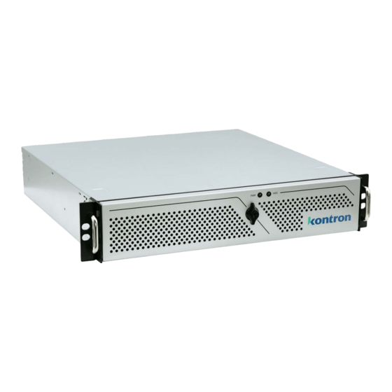
KISS 2U V4 ADL - User Guide, Rev.1.0 4/ Product Features Front Panel The front panel features a power button, power LED, HDD LED, magnetic filter pad door and supports different front panel internal or external drive bay options. To mount the product in a 19” rack mounting, optional 19” rack handles are available, see Table 2: Accessories and Spares Parts. -
Page 23: Front Flap
KISS 2U V4 ADL - User Guide, Rev.1.0 4.1.1. Front Flap To protect against unauthorized access, an optional front flap with front flap side panels is available, see Table 2: Accessories and Spares Parts. Figure 4: Front Flap Front flap... -
Page 24: Handle Brackets
KISS 2U V4 ADL - User Guide, Rev.1.0 4.1.3. Handle Brackets When using the handle brackets always attach both handle brackets to the product firmly, using the two screws provided (Figure 5, pos. 1). When mounting the product in a 19” rack always secure the product using both handle brackets and screws suitable for the mount environment (Figure 5, pos. -
Page 25: Power Button
KISS 2U V4 ADL - User Guide, Rev.1.0 4.1.5. Power Button The power button is located on the front panel, behind the front flap and is used to switch on or switch off the product. Pressing the power button for longer than four seconds initiates a forced system shutdown before the switching off the product. -
Page 26: Usb Ports
KISS 2U V4 ADL - User Guide, Rev.1.0 4.1.7. USB Ports The two USB 3.0 ports are (USB 3.2 Gen 1) and located on the front panel, behind the front flap. Figure 8: USB 3.2 Gen 1 Port If USB devices are connected to the USB ports on the front side, the front flap cannot be closed and locked. -
Page 27: Rear Panel
KISS 2U V4 ADL - User Guide, Rev.1.0 Rear Panel The rear panel features the PSU, air exhaust ventilation openings, external interfaces, and expansion card slots. The different rear panels low profile and riser card support different PCIE/PCI expansion cards sizes and quantities. -
Page 28: Display Port (Dp)
KISS 2U V4 ADL - User Guide, Rev.1.0 Figure 10: Rear Panel (riser card) Input power sockets (shown with 1x Serial port (RS232) optional redudant power supply) 1x USB-C 3.2 Gen 2 4x DP 1.4 @ 4K 1x Audio 1x 1.0 GbE 10 Slot 1: PCIE (full height, full length) 2x USB 3.2 Gen 1... -
Page 29: Usb 3.2
KISS 2U V4 ADL - User Guide, Rev.1.0 Connection to either a VGA, DVI or HDMI video source is possible using either a passive or active adapter. The type of adapter depends on the signal type and if the connection is to a single device or multiple devices. -
Page 30: Serial Ports (Com)
KISS 2U V4 ADL - User Guide, Rev.1.0 4.2.4. Serial Ports (COM) The serial port provides full RS232 support. Three additional RS232 serial ports can be routed from the motherboard to the rear panel to populate the available breakouts, see Figure 9, pos. 17 and Figure 10, pos. 13. -
Page 31: Table 6: Redundant Psu Led Description
KISS 2U V4 ADL - User Guide, Rev.1.0 Do not disconnect the power from the system while the system is switched on! Performing a forced shut down can lead to loss of data or other undesirable effects! The default PSU is a single 400 W PSU, with the option for a redundant 550 W PSU for high availability applications. -
Page 32: Potential Equalization Stud
KISS 2U V4 ADL - User Guide, Rev.1.0 PSU LED Power Supply Description Amber Main AC power cable unplugged or AC power lost; with a second power supply in parallel still with AC input power. Amber (Flashing) Power supply warning events where the power supply continues to operate, such as: high temperature, high power, high current, slow fan. -
Page 33: Side
KISS 2U V4 ADL - User Guide, Rev.1.0 Side The sides feature a fastening mechanism to hold the cover in place using a push button with metal catch and corresponding indents and hooks to secure the sides of the cover. -
Page 34: Figure 15: Cover Top Side (Low Profile)
KISS 2U V4 ADL - User Guide, Rev.1.0 Figure 15: Cover Top Side (low profile) Two indented thumb holes Expansion card plate (low profile) Figure 16: Cover Underside (low profile) Three hooks Two studs Lock hole for metal catch Expansion card plate Front side pins www.kontron.com... -
Page 35: System Configuration
KISS 2U V4 ADL - User Guide, Rev.1.0 System Configuration Figure 17: Example of KISS 2U V4 ADL Configuration Cover retaining plate on front side Fastening screws for slot brackets or expansion card slot brackets Side fastening mechanism Six PCIe slots+ one PCI slot... -
Page 36: 5/ System Expansion
KISS 2U V4 ADL - User Guide, Rev.1.0 5/ System Expansion This chapter contains important information on how to expand the KISS 2U V4 ADL with storage and expansion cards. Before Expanding Before expanding the product with storage and expansion cards, consider the maximum power consumption allowed by the power supply. -
Page 37: Expansion Cards
PSU is not exceeded. 5.4.1. Reference PCIe Expansion Cards The Kontron reference low profile PCIe expansion cards supports the following functions: Table 10: Reference KISS 2U V4 ADL PCIe Expansion Cards Reference Card Description LAN Dual 1.0 GbE Copper Port... - Page 38 Interface: PCIe 3.0 x16 Form factor: Single slot Power consumption: 40 W Max. simultaneous displays: 4x 3840x2160@120Hz 4x 5120x2880@60Hz 2x 7680x4320@60Hz Others PCIe/PCI expansion card options are available on request. For more information, contact Kontron Support. www.kontron.com // 38...
-
Page 39: 6/ Thermal Management
When clogged, the filter pad restricts the amount of air entering the product thus causing excessive heating. Kontron recommends cleaning the filter pad as often as necessary, see Chapter 13.3: Cleaning the Filter Pad. -
Page 40: Third Party Components
KISS 2U V4 ADL - User Guide, Rev.1.0 There are no ventilation restrictions above and below the product, enabling installation directly on top of or below another system. Third Party Components When expanded with third party components, such as PCIe/PCI expansion cards, M.2 modules, DIMMs and drives (HDD, SSD, DVD), take into consideration that there is an increase in air temperature inside the chassis and the air temperature in the chassis is higher than the ambient air temperature around the product. -
Page 41: 7/ Assembly
7/ Assembly This chapter contains important information on the mechanical assembly and working safely with internal components. Follow these instructions when handling KISS 2U V4 ADL internal components and observe the corresponding safety instruction included in Chapter 2/ General Safety Instructions. -
Page 42: Installing And Removing Pcie/Pci Expansion Cards (Low Profile Variant)
KISS 2U V4 ADL - User Guide, Rev.1.0 Figure 18: Push Button (left and right side) Metal catch Push button To open the cover, perform the following: Place both thumbs in the indented thumb-holes on the cover (Figure 15, pos. 1) and index fingers on the push button on the left and right sides of the chassis (Figure 18, pos. -
Page 43: Installing And Removing Pcie Expansion Cards (Riser Card Variant)
KISS 2U V4 ADL - User Guide, Rev.1.0 Figure 19: Installing Low Profile Expansion Cards 7x Slot bracket screws 7x Slot bracket latches To install a low profile expansion card, perform the following: Switch off and disconnect the product from the mains power supply. -
Page 44: Installing And Removing The Handle Brackets
KISS 2U V4 ADL - User Guide, Rev.1.0 Figure 20: Installing Riser Card Expansion Cards Slot bracket screws Sliding screw Slot bracket latches Small rear side panel To install an expansion card in the riser card, perform the following: Switch off and disconnect the product from the mains power supply. -
Page 45: Installing And Removing The Front Flap
Return the product to the upright position with the cover facing upwards. Installing Slide Rails Kontron offers compatible 19” Slide Rails and Rack Slide Rails Kit for the KISS 2U V4-ADL. For more information, see Table 2: Accessories and Spares Parts. To install the slide rails, proceed as follows: Extend the slide rail to the pulled-out position to expose the inner part of the slide rail with screw holes. -
Page 46: 8/ Mounting
KISS 2U V4 ADL - User Guide, Rev.1.0 8/ Mounting This chapter contains important information on how to mount the KISS 2U V4 ADL in a 19” Industrial rack and in customer specific environments. Before Mounting Before mounting the product, read the instructions in this chapter and observe the information in Chapter 2/: General Safety Instructions. -
Page 47: Mounting On A Desktop
KISS 2U V4 ADL - User Guide, Rev.1.0 Mounting on a Desktop Before installing the product in a desktop environment, install the delivered rubber feet, to avoid scratching the installation surface. Additionally, observe the general instructions and any safety warnings within this chapter. - Page 48 KISS 2U V4 ADL - User Guide, Rev.1.0 Installing the product alone can result in product damage or personal injury. Due to possible access restrictions, before installing the product install all expansion cards and connect required peripherals to the corresponding system ports.
-
Page 49: 9/ Starting Up
KISS 2U V4 ADL - User Guide, Rev.1.0 9/ Starting Up This chapter contains important information on how to connect to a power supply and start the KISS 2U V4 ADL. Before Starting Before starting up observe the instructions within this chapter and refer to Chapter 2/ General Safety Instructions. -
Page 50: Connecting To The Redundant Power Supply (Option)
KISS 2U V4 ADL - User Guide, Rev.1.0 Do not disconnect the power while the product is in operation. Performing a forced shut down can lead to loss of data or other undesirable effects! Connecting to the Redundant Power Supply (option) The redundant 550 W power supply contains two separate power supplies where each power supply is capable of powering the product alone. -
Page 51: Operating System And Hardware Component Drivers
Operating System and Hardware Component Drivers The product is fully operational when switched on for the first time with pre-installed Operating System (OS) Windows 10 IoT x64 or Linux Ubuntu 64-bit and with all required drivers. Drivers are available from Kontron’s Customer Section. -
Page 52: 10/ Bios
KISS 2U V4 ADL - User Guide, Rev.1.0 BIOS The KISS 2U V4 ADL uses the uEFI BIOS supported by the motherboard. This chapter informs user how to start the BIOS, use the BIOS setup to configure, and perform a BIOS update. -
Page 53: Bios Navigation
The latest BIOS updates and BIOS release information for the product is available by accessing the Motherboard FTP server on Kontron’s Customer Section Website by selecting Motherboards & SBC > ATX > K3851-R ATX > Link to the FTP Server. The FTP server provides operators with downloads of the latest BIOS version and general BIOS information. -
Page 54: Recover Bios
KISS 2U V4 ADL - User Guide, Rev.1.0 For the latest BIOS updates and BIOS release information, visit Kontron’s Customer Section Website and select: Motherboards & SBC > ATX > K3851-R ATX > Link to the FTP Server. Recover BIOS... -
Page 55: 11/ Product Specification
KISS 2U V4 ADL - User Guide, Rev.1.0 11/ Product Specification This chapter described the technical specifications of the KISS 2U V4 ADL Block Diagram Figure 25: Block Diagram KISS 2U V4 ADL (low profile) KISS 2U V4 ADL Low Profile ATX Mainboard Intel®... -
Page 56: Figure 26: Block Diagram Kiss 2U V4 Adl (Riser Card)
KISS 2U V4 ADL - User Guide, Rev.1.0 Figure 26: Block Diagram KISS 2U V4 ADL (riser card) KISS 2U V4 ADL Riser Card ATX Mainboard Intel® 12th/13th Gen Core™ i9/i7/i5/i3 Processors Intel® R680E Chipset 2x System Fans 1x M.2 2280 2x USB 3.2 Gen 1... -
Page 57: Hardware Specification
KISS 2U V4 ADL - User Guide, Rev.1.0 Hardware Specification Table 12: Hardware Specification Product KISS 2U V4 ADL Low profile KISS 2U V4 ADL Riser card Motherboard Type K3851-R ATX Processor Intel® 12 /13th Gen Core™ i9, i7, i5 und i3 Processors... -
Page 58: Software Specification
KISS 2U V4 ADL - User Guide, Rev.1.0 Product KISS 2U V4 ADL Low profile KISS 2U V4 ADL Riser card Expansion Cards PCIe /PCI cards Slot 1: 1x PCIe x16, Gen 5, 16 lanes 2xPCIe x8 slots (full height, full length) -
Page 59: Environmental Specification
KISS 2U V4 ADL - User Guide, Rev.1.0 Easy Access to Power Cable and Power Connectors The power cable must always remain easily accessible. If the end environment restricts access to power cable, disconnection must be guaranteed using a separate cut-off fixture. -
Page 60: Mechanical Specification
For detailed mechanical dimensions, visit Kontron’s Customer Section. Compliance The KISS 2U V4 ADL plans to comply with the relevant requirements and the approximation of the laws relating to the CE Mark and the standards that are constitutional parts of the declaration. -
Page 61: Table 18: International Compliance
Kontron is not responsible for any radio television interference caused by unauthorized modifications of the delivered product or the substitution or attachment of connecting cables and equipment other than those specified by Kontron. The correction of interference caused by unauthorized modification, substitution or attachment is the user’s responsibility. -
Page 62: 12/ Standard Interfaces- Pin Assignment
KISS 2U V4 ADL - User Guide, Rev.1.0 Standard Interfaces- Pin Assignment DP Port Pin Assignment Table 19: DP V1.4a Pin Assignment Signal Name Signal Name DPP (V1.4) Connector Link0+ Link0- Link1+ Link1- Link2+ Link2- Link3+ Link3- DVI dongle detect... -
Page 63: Usb-C 3.2 Gen 2 Port Pin Assignment
KISS 2U V4 ADL - User Guide, Rev.1.0 USB-C 3.2 Gen 2 Port Pin Assignment Table 21: USB 3.2 Gen 2 Type C Pin Assignment Pin-A Signal Name Pin-B Signal Name USB 3.2 Gen 2-C Type Connector USB3_TX1+ USB3_RX+ USB3_TX1-... -
Page 64: Com Port Pin Assignment
KISS 2U V4 ADL - User Guide, Rev.1.0 LAN Cabling 1000Base-T CAT 5E/6 or higher up to 100m 100Base-T CAT 5/5E/6 or higher up to 100m 10Base-T CAT 3/4/5/5E/6 or higher up to 100m COM Port Pin Assignment Table 23: RS232 Connector Pin Assignment... -
Page 65: M.2 Key M (Nvme Ssd) Socket Pin Assignment
KISS 2U V4 ADL - User Guide, Rev.1.0 M.2 Key M (NVME SSD) Socket Pin Assignment Table 25: M.2 Key M Socket Pin Assignment Signal Name Signal Name M.2 Key M +3.3V +3.3V PCIe RX 3- PCIe RX 3+ LED SSD PCIe TX 3- +3.3V... -
Page 66: Jumpers
Figure 27: Recover BIOS Jumper Default jumper setting Recover position (orange) Table 26: Recover BIOS Jumper Pins State 24-pin Front Panel Header 20-22 Default 22-24 Recover BIOS Default Recover BIOS For further motherboard information, visit Kontron’s K3851-R ATX motherboard website. www.kontron.com // 66... -
Page 67: 13/ Maintenance And Prevention
Maintenance and Prevention Maintenance or repair may only be carried out by Kontron authorized qualified personnel. The KISS 2U V4-ADL only require minimal maintenance and care to keep them operating correctly. Clean the air filter pad regularly (as often as necessary), the time-period will depend on the level of contaminates with in the operating environment. -
Page 68: Replacing The System Fans
KISS 2U V4 ADL - User Guide, Rev.1.0 Figure 28: Removing the Filter Pad Magnetic filter pad door with filter Filter pad door’s opening pad behind Front flap To remove and clean or replace the filter pad, perform the following: Open the front flap (Figure 28, pos. -
Page 69: Replacing The Lithium Battery
(Figure 29, pos. 2). Replace the fan with a Kontron spare part fan, Table 2: Accessories and Spares Parts, by connecting to the fan to the fan connector (Figure 29, pos. 2). -
Page 70: Replacing The Internal 2.5" Ssd Drive
Figure 30: Lithium Battery (CR2032) Lithium battery CR2032 Replaced the lithium battery only with the same type of battery or with a type of battery recommended by Kontron. To replace the factory installed lithium battery (CR2032) on the motherboard, perform the following: Switch off and disconnect the product properly from the mains power supply. -
Page 71: Replacing A M.2 Ssd Module
KISS 2U V4 ADL - User Guide, Rev.1.0 Position the new 2.5” SSD in the metal bracket and secure with the four screws retained in step 5. Attach the SATA data and SATA power cable to the 2.5” SSD drive. - Page 72 KISS 2U V4 ADL - User Guide, Rev.1.0 The redundant PSU enables hot swap of faulty PSU units. To replace a faulty redundant PSU unit, perform the following: Locate the faulty PSU unit with the illuminated indication LED, see Table 6: Redundant PSU LED Description.
-
Page 73: 14/ Technical Support
RMA number. The buyer accepts responsibility for all freight charges for the return of goods to Kontron's designated facility. Kontron will pay the return freight charges back to the buyer's location in the event that the equipment is repaired or replaced within the stipulated warranty period. Follow these steps before returning any product to Kontron. -
Page 74: 15/ Warranty
Limitation/Exemption from Warranty Obligation In general, Kontron shall not be required to honor the warranty, even during the warranty period, and shall be exempted from the statutory accident liability obligations in the event of damage caused to the product due to failure to observe the following: ... -
Page 75: List Of Acronyms
KISS 2U V4 ADL - User Guide, Rev.1.0 List of Acronyms Table 27: List of Acronyms Advanced Technology eXtended Secure Shell BIOS Basic Input Output System Trusted Computer Group Communication port TFTP Trivial File Transfer Protocol Central Processing Unit Trusted Platform Module... -
Page 76: About Kontron
KISS 2U V4 ADL – User Guide, Rev.1.0 About Kontron Kontron is a global leader in IoT/Embedded Computing Technology (ECT). Kontron offers individual solutions in the areas of Internet of Things (IoT) and Industry 4.0 through a combined portfolio of hardware, software and services.
Need help?
Do you have a question about the KISS 2U V4 ADL and is the answer not in the manual?
Questions and answers