Table of Contents
Advertisement
Quick Links
Advertisement
Table of Contents

Related Manuals for Kontron TIGW1U


Summary of Contents for Kontron TIGW1U
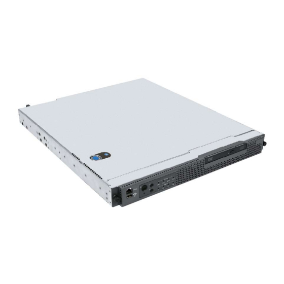
- Page 1 Kontron Carrier Grade Server TIGW1U Product Guide December 2009 Rev. 1.3...
- Page 2 All rights reserved. All data is for information purposes only and not guaranteed for legal purposes. Information has been carefully checked and is believed to be accurate; however, no responsibility is assumed for inaccuracies. Kontron and the Kontron logo and all other trademaarks or registed trademarks are the property of their respective owners and are recognized.
-
Page 3: Table Of Contents
Internal System Component Installation Procedures ......30 3.4.1 Configuring Jumpers on the Server Board .......31 3.4.1.1 Jumper Blocks ............31 3.4.1.2 CMOS Clear and Password Reset Procedures .....32 3.4.1.3 BMC Force Update Procedure ........32 Kontron Carrier Grade Server TIGW1U December 2009 Product Guide, rev. 1.3... - Page 4 Installing the Server into a Rack ............68 3.6.1 Connecting the Power Cord ..........68 3.6.2 Equipment Rack Precautions ..........68 Server Utilities ..................71 Using the BIOS Setup Utility ............71 4.1.1 Starting Setup ..............71 Kontron Carrier Grade Server TIGW1U Product Guide, rev. 1.3 December 2009...
- Page 5 B.1.1 Product Safety Compliance ...........99 B.1.2 Product EMC Compliance - Class A Compliance .......99 B.1.3 Certifications / Registrations / Declarations ......99 Electromagnetic Compatibility Notices ..........100 B.2.1 FCC (USA) ...............100 Kontron Carrier Grade Server TIGW1U December 2009 Product Guide, rev. 1.3...
- Page 6 Europe (CE Declaration of Conformity) .........101 B.2.4 VCCI (Japan) ..............101 B.2.5 BSMI (Taiwan) ..............101 B.2.6 Regulated Specified Components ........102 Getting Help ..................103 World Wide Web ................103 Telephone ..................103 Emai ..................l103 Kontron Carrier Grade Server TIGW1U Product Guide, rev. 1.3 December 2009...
-
Page 7: Revision History
—TIGW1U server Revision History Date Revision Description December 2009 Kontron version; Changed all Z-U130 drive references to SMART Embedded USB Solid-State Drive ® ® Edited processor information to include Quad-Core Intel Xeon processors 5400 series. Minor grammar and formatting changes. - Page 8 TIGW1U server— Kontron Carrier Grade Server TIGW1U Product Guide, rev. 1.3 December 2009...
-
Page 9: About This Manual
Manual Organization Chapter 2 provides a brief overview of the TIGW1U server. In this chapter, you will find a list of the server board features, chassis features, illustrations of the product, and product diagrams to help you identify components and their locations. -
Page 10: Product Accessories
Additional Information and Software If you need more technical information about this product or information about the accessories that can be used with this TIGW1U server, see the Technical Product Specifications (for both system and server board) and the test reports at http://us.kontron.com/support/... - Page 11 December 2009Introduction—TIGW1U server • System drivers Kontron Carrier Grade Server TIGW1U December 2009 Product Guide, rev. 1.3...
- Page 12 TIGW1U server—December 2009Introduction Kontron Carrier Grade Server TIGW1U Product Guide, rev. 1.3 December 2009...
-
Page 13: Features
This chapter briefly describes the main features of the Kontron Carrier Grade Server TIGW1U. This chapter provides a diagram of the product, a list of the server features, and diagrams showing the location of important components and connections on the server system. - Page 14 Upgradeability and Note: Quad-Core Intel Xeon processor 5400 series support is available only on investment protection TIGW1U server systems that have product codes TMRA0201W and TMRD0201W.Multi-generational chassis ® Supports Intel 64 architecture Supports 24 Gbyte DDR2-533 or DDR2-667 MHz Registered SDRAM FBD DIMM memory ®...
-
Page 15: Server Components
Features—TIGW1U server Server Components Figure 2 shows the internal components of the TIGW1U server (top cover and front bezel removed). Figure 2. Carrier Grade Server TIGW1U Components AF000801 Item Description Item Description SAS front panel (SFP) board System fans Power distribution board (PDB) -
Page 16: Back Panel
Power supply #2 Keyboard connector Front Panel Figure 4. Front View (Bezel Installed) AF000806 Item Description Item Description RJ45 serial port (COM2/Serial B) Optical drive Control panels USB port 2 Kontron Carrier Grade Server TIGW1U Product Guide, rev. 1.3 December 2009... - Page 17 An example is the loss of a large section of memory, or other corruption, that renders the system non-operational. The front panel critical alarm relay engages. Kontron Carrier Grade Server TIGW1U December 2009 Product Guide, rev. 1.3...
-
Page 18: Rear Panel Ethernet Ports
NIC PCI Express* (PCIe*) or PCI-X* card with rear I/O panel access ports. There are no GbE NIC ports accessible from the front of the TIGW1U server. The GbE NIC ports are intended to be installed with shielded cabling that is grounded at both ends of the cable. -
Page 19: Server Board Connector And Component Locations
RMM NIC connector Serial Port A header PCI Express/PCI-X riser card super slot Main power connector POST code diagnotic LEDs PATA (IDE) connector Dual-port LAN connector Password clear jumper (J1H2) Kontron Carrier Grade Server TIGW1U December 2009 Product Guide, rev. 1.3... -
Page 20: Hard Disk Drives
Replacing a Hard Drive”. Note: The TIGW1U server does not support all SAS hard drives. For a list of validated hard drive manufacturers and hard drive types, see the Tested Hardware and Operating Systems List (THOL) on the Kontron support website at http://us.kontron.com/support/. -
Page 21: Pci Express Riser Card
The power supply is rated for 450 W output capability in full AC (or DC) input voltage range. 2.10 System Cooling There are three cooling areas in the TIGW1U server: front panel board area, PCI area, and CPU-memory-HDD area. Figure 8. Cooling Areas... -
Page 22: Front Panel Cooling Area
Channel 0 consists of DIMM sockets A1, A2, and A3. Channel 1 consists of DIMM sockets B1, B2, and B3. See Section 3.4.2, “Configuring Memory DIMMs” on page 34 for population rules and configuration information. Kontron Carrier Grade Server TIGW1U Product Guide, rev. 1.3 December 2009... -
Page 23: Server Installations And Upgrades
Cable Routing Reference It is important for cables to be connected correctly. See Figure 9. For more detailed information about cable connectors, see the Kontron Carrier Grade Server TIGW1U Technical Product Specification. Kontron Carrier Grade Server TIGW1U December 2009 Product Guide, rev. 1.3... -
Page 24: General Installation Procedures
3.2.1 Removing the Chassis Cover The TIGW1U server must be operated with the top cover in place to ensure proper cooling. You need to remove the top cover to add or replace components inside of the server. Before removing the top cover, power down the server system and unplug all peripheral devices and the power cable. -
Page 25: Installing The Chassis Cover
Server Installations and Upgrades—TIGW1U server Note: A non-skid surface or a stop behind the server may be needed to prevent the server from sliding on your work surface. 1. Observe the safety and ESD precautions in Appendix A, “Safety Information”. -
Page 26: Installing The Front Bezel
TIGW1U server—Server Installations and Upgrades Figure 11. Removing the Front Bezel TS000202 3.2.4 Installing the Front Bezel While holding the front bezel in place, tighten the captive screws at the left and right edges of the bezel. 3.2.5 Removing the Processor Air Duct The air duct must be removed to access the processors, memory DIMMs, and the four- fan assembly. -
Page 27: Installing The Processor Air Duct
If you install fewer than three hard drives, the empty bays must be populated with drive trays that have baffles in them to maintain proper system cooling. The Carrier Grade Server TIGW1U does not support all SAS hard drives. To see a list of validated manufacturers and hard drive types, go to: http://us.kontron.com/support/... -
Page 28: Removing A Hard Drive Tray From The Chassis
TIGW1U server—Server Installations and Upgrades 3.3.1.1 Removing a Hard Drive Tray from the Chassis 1. Remove the front bezel. For instructions, see Section 3.2.3, “Removing the Front Bezel” on page 2. Select the drive bay where you want to install the drive. Remove the drive tray by pressing the green button to open the lever. -
Page 29: Replacing A Power Supply Module
Server Installations and Upgrades—TIGW1U server 2. Install the new drive in the drive tray and secure the drive with the four screws that come with the drive tray. (“A” and “B” in Figure Figure 15. Installing a Hard Drive AF000810 3. -
Page 30: Removing The Power Supply Module
TIGW1U server—Server Installations and Upgrades To maintain hot-swap capability, make sure an active power supply module is in each chassis slot before replacing (hot-swapping) a power supply module. 3.3.2.1 Removing the Power Supply Module 1. Check the status LED to determine which power supply has failed (“A” in Figure 17). -
Page 31: Configuring Jumpers On The Server Board
The jumpers are located on the S5000PHB server board server board, which is in the rear left side of the TIGW1U server chassis. To configure the jumpers on the server board, in adddition to removing the chassis cover, you also must remove the processor air duct (see Section 3.2.5, “Removing the Processor Air Duct”... -
Page 32: Cmos Clear And Password Reset Procedures
TIGW1U server—Server Installations and Upgrades 3.4.1.2 CMOS Clear and Password Reset Procedures The procedure is identical for clearing the CMOS and the password, but has changed from previous generation server boards. The following steps outline the new procedure for both operations. -
Page 33: Bios Select Jumper
3.4.1.5 Serial B Port Configuration Jumper The rear of the Carrier Grade Server TIGW1U provides an RJ45 connector for the Serial B port, which is intended for direct connection to serial devices such as serial port concentrators using a standard Cat 5 cable. -
Page 34: Configuring Memory Dimms
TIGW1U server—Server Installations and Upgrades CAUTION: Jumper J3E2 must be configured to match your installed ® for Dual-Core Intel processor or your system will not boot ® Xeon Processor properly. 5100 Series: Server Install jumper Board over pins 1-2. 1 2 3 ®... -
Page 35: Dimm Population Rules
Server Installations and Upgrades—TIGW1U server The two channels support registered DDR2-533 and DDR2-667 FBDIMM memory (stacked or unstacked). Peak theoretical memory data bandwidth is 6.4 Gbytes/s with DDR2-533 or 8.0 Gbytes/s with DDR2-667. Table 4 Table 5 show the maximum memory configurations supported using the specified memory technology. -
Page 36: Sparing Mode Memory Configuration
TIGW1U server—Server Installations and Upgrades 3.4.2.3 Sparing Mode Memory Configuration The Memory Controller Hub (MCH) provides memory sparing capabilities. Sparing is a RAS feature that involves configuring a DIMM to be placed in reserve so it can be use to replace a DIMM that fails. -
Page 37: Removing Dimms
The processor must be appropriate: You could damage the server board if you install a processor that is inappropriate for your server. Go to http://us.kontron.com/support/ for a list of compatible processors for the TIGW1U server. 3.4.4.1 ESD and Handling Processors •... -
Page 38: Removing A Processor
TIGW1U server—Server Installations and Upgrades Figure 20. Cautions for Handling Processors Follow the instructions below to remove and then install a processor, referring to Figure 21 through Figure 3.4.4.2 Removing a Processor 1. Remove the processor air duct that covers the processor. For instructions, Section 3.2.5, “Removing the Processor Air Duct”... -
Page 39: Installing A New Processor
Server Installations and Upgrades—TIGW1U server Figure 22. Using the Socket Lever AF000768 6. Pull the lever and open the load plate all the way. (“A” and “B” in Figure Figure 23. Opening the Load Plate AF000769 7. Remove the processor. - Page 40 TIGW1U server—Server Installations and Upgrades Caution: The underside of the processor has components that may damage the socket pins if installed improperly. The processor must align correctly with the socket. Set the processor carefully into the socket! 2. Orient the processor with the socket so that the processor cutouts match the socket notches.
-
Page 41: Setting The Processor Select Jumper
Server Installations and Upgrades—TIGW1U server 5. Close the load plate. (Figure 27, “A”) Figure 27. Closing the Processor Load Plate and Socket Lever AF000773 6. Close the socket lever and ensure that the load plate tab engages under the socket lever when fully closed. -
Page 42: Installing Or Replacing A Pci Add-In Card
Note: Use a supported PCI/PCIe card. For a list of tested and supported cards,see the Tested Hardware and Operating System List (THOL) at http://us.kontron.com/support/. Search for TIGW1U, click on Product Downloads, and then 3.4.5.1 Removing the PCI Riser Card Assembly To remove an installed riser card assembly, follow these steps: 1. -
Page 43: Removing A Pci Card From The Riser Card Assembly
Server Installations and Upgrades—TIGW1U server Figure 28. Removing the Riser Card Assembly TS000211 3.4.5.2 Removing a PCI card from the Riser Card Assembly Caution: When handling a PCI card, observe safety and ESD precautions. See Appendix A, “Safety Information” for more information. - Page 44 TIGW1U server—Server Installations and Upgrades a. With the riser card assembly upside-down, remove the riser card by loosening the two screws that attach it to the riser card assembly sheet metal top. b. Fasten the new riser card, i.e., the PCIe riser card in this example, using the two screws.
-
Page 45: Installing The Riser Card Assembly Onto The Server Board
Server Installations and Upgrades—TIGW1U server 3.4.5.4 Installing the Riser Card Assembly onto the Server Board 1. Align the fork on the riser card assembly with the pin on the rear chassis panel. (“A” in Figure 2. Attach the riser card assembly to the server board by inserting the riser card edge connector into the super slot header on the server board. -
Page 46: Installing A Smart Embedded Usb Solid-State Drive
TIGW1U server—Server Installations and Upgrades 3.4.6 Installing a SMART Embedded USB Solid-State Drive The SMART Embedded USB Solid-State Drive (eUSB SSD) is a removable media device that provides local memory storage for options like system information, diagnostic partitions, and configuration data. The solid-state drive is installed on top of the drive bays in front of the SFP board. -
Page 47: Installing Hardware Raid Components
Figure 9 for the connector locations. Please refer to the TIGW1U Spares and Configuration Guide for these parts. The RAID mini-DIMM may also be procured from the list of approved vendors in the Server Board S5000PHB Tested Memory List at http://www.cmtlabs.com/mbSearchResults.asp?sManuf=Kontron&sMem=FB-... -
Page 48: Installing The Intel
TIGW1U server—Server Installations and Upgrades ® 3.4.7.1 Installing the Intel RAID Smart Battery ® The Intel RAID Smart Battery is located just behind the front panel near HDD drive bay 0. The connector is on the far right end of the SAS Front Panel (SFP) board. - Page 49 Server Installations and Upgrades—TIGW1U server 6. Align the two hooks on the underside of the Smart Battery with the matching tabs on the chassis. (“A” in Figure 7. Slide the Smart Battery toward the front panel to lock it in place. (“B”) 8.
-
Page 50: Dimm
3.5.1 Replacing an Optical Device A DVD-ROM device comes pre-installed in the Carrier Grade Server TIGW1U. This device is not hot-swappable. To replace the drive, you must first power down the system and remove the chassis cover as described in Section 3.2, “General Installation... -
Page 51: Removing The Optical Device Tray From The Chassis
Server Installations and Upgrades—TIGW1U server 3.5.1.1 Removing the Optical Device Tray from the Chassis 1. Disconnect the power and data connectors from the interposer board on the back of the optical drive. 2. Loosen the blue captive thumbscrew on the optical drive tray. (“A” in Figure 3. -
Page 52: Installing A New Optical Drive
TIGW1U server—Server Installations and Upgrades 3.5.1.2 Installing a New Optical Drive 1. Connect the interposer board to the back of the optical drive. (“A” in Figure Figure 39. Connecting the Optical Drive Interposer Board TS000221 2. Place the new optical drive into the drive tray. (“A” in Figure Figure 40. -
Page 53: Replacing A Fan Assembly
Server Installations and Upgrades—TIGW1U server Figure 41. Installing the Drive Tray with Optical Drive Attached into the Server TS000223 4. Connect the power and data cables back onto the interposer board. 5. If this is the only change you are making, attach the front bezel and cover and reconnect the power to the chassis. -
Page 54: Replacing The Cpu Four-Fan Assembly
TIGW1U server—Server Installations and Upgrades 3.5.2.1 Replacing the CPU Four-Fan Assembly 1. Remove the processor air duct that covers the processor and cooling area behind the drive trays. For instructions, see Section 3.2.5, “Removing the Processor Air Duct” on page 2. -
Page 55: Replacing The Pci Fan
Server Installations and Upgrades—TIGW1U server Figure 44. Installing Fans into the Four-Fan Assembly Bracket TS000297 7. Connect the fan cables to the correct fan connectors on the SFP board. The fan connectors are labeled on the SFP board. 3.5.2.2 Replacing the PCI Fan 1. -
Page 56: Replacing The Sas Front Panel Board
• LED light pipes to the front panel Caution: Before replacing any of the TIGW1U server boards, you must first take the server out of service, turn off all peripheral devices connected to the system, turn off the system by pressing the power button, and unplug the power cord from the system or wall outlet. - Page 57 Server Installations and Upgrades—TIGW1U server 5. Disconnect these cables from the SFP board: — Front panel data — Front panel USB — All fan power cables — Flex cable — Optical device power cable — Power interconnect to PDB 6. Remove the screws (“A”).
-
Page 58: Replacing The Light Pipe Assembly
TIGW1U server—Server Installations and Upgrades 3.5.3.2 Replacing the Light Pipe Assembly To replace the light pipe assembly on an existing SFP board, use the following instructions, but replace the existing SFP board instead of installing a board: • Removing the SAS Front Panel (SFP) Board •... -
Page 59: Remote Management Module 2
Server Installations and Upgrades—TIGW1U server ® 3.5.4 Installing the Intel Remote Management Module 2 ® To install the GCM module and the Intel Remote Management Module 2 ® (Intel RMM2), you must first remove the chassis top cover, the processor air duct, and PCI riser card assembly. - Page 60 TIGW1U server—Server Installations and Upgrades Figure 49. Installing the Remote Management Module 2 RMM Module GCM3 Module TS000414 Kontron Carrier Grade Server TIGW1U Product Guide, rev. 1.3 December 2009...
-
Page 61: Replacing The Power Distribution Board
Use the following instructions to replace the PDB. Caution: Before replacing any board in the TIGW1U server, you must first take the server out of service, turn off all peripheral devices connected to the system, turn off the system by pressing the power button, and unplug the power cord from the system or wall outlet. -
Page 62: Replacing The Server Board
4. Install the PCI fan air duct and the chassis cover. 3.5.6 Replacing the Server Board ® The Carrier Grade Server TIGW1U uses the Intel Server Board S5000PHB server board. To replace the server board, the following components must be removed: All components on the server board: •... -
Page 63: Installing The Server Board Back Into The Chassis
Server Installations and Upgrades—TIGW1U server 5. Remove the heat sink(s) and processor(s). For instructions, see Section 3.4.4.2, “Removing a Processor” on page 6. Remove the four-fan assembly, including the bracket. 7. Disconnect all cables from the server board. 8. Remove the screws that attach the server board to the chassis. (“A” in Figure 9. -
Page 64: Replacing The Cmos Battery On The Server Board
When the battery starts to weaken, it loses voltage, and the server settings (for example, the date and time) stored in CMOS RAM (Random Access Memory) in the RTC may be wrong. Contact your Kontron sales representative or dealer for a list of approved devices. - Page 65 Server Installations and Upgrades—TIGW1U server Caution: Before replacing the battery, you must first take the server out of service, turn off all peripheral devices connected to the system, turn off the system by pressing the power button, and unplug the power cord from the system or wall outlet.
- Page 66 TIGW1U server—Server Installations and Upgrades Figure 54. Replacing the Battery TS000416 7. Dispose of the battery according to local ordinance. 8. Being careful to observe the correct polarity, insert the new battery into the socket. 9. Re-install the processor air duct and the chassis cover.
-
Page 67: Installing The Battery Insulator
Server Installations and Upgrades—TIGW1U server 3.5.8 Installing the Battery Insulator If you are installing the battery on a new server board or replacing it on a server board that does not have the protective insulator surrounding the battery, use the following procedure to install the insulator. -
Page 68: Installing The Server Into A Rack
TS000418 Installing the Server into a Rack Installation instructions for the standard bracket kit and the optional rail kit are included with each kit. These instructions can also be found on the Kontron Deployment Assistant CD and at http://us.kontron.com/support/. Search for TIGW1U. - Page 69 Ventilation: The equipment rack must provide sufficient airflow to the front of the server to maintain proper cooling. It must also include ventilation sufficient to exhaust a maximum of 1200 BTU per hour for a fully loaded server system using the Kontron Carrier Grade Server TIGW1U.
- Page 70 TIGW1U server—Server Installations and Upgrades Kontron Carrier Grade Server TIGW1U Product Guide, rev. 1.3 December 2009...
-
Page 71: Server Utilities
Using the BIOS Setup Utility This section describes the BIOS Setup Utility options, which is used to change configuration defaults for the Kontron Carrier Grade Server TIGW1U. You can run BIOS Setup with or without an operating system being present. See the Kontron Carrier Grade Server TIGW1U Technical Product Specification for details about specific BIOS setup screens. -
Page 72: Cmos Clear And Password Reset Procedure
(Pins 2-3). For the location of this jumper, see Figure 4. Wait 5 seconds. 5. Move the jumper back to the default position (Pins 1-2). 6. Close the server. Kontron Carrier Grade Server TIGW1U Product Guide, rev. 1.3 December 2009... -
Page 73: Bmc Force Update Procedure
In the unlikely event that a BIOS error occurs during the BIOS update process, a recovery process may need to be followed to return the system to service. See Section 1.4, “Additional Information and Software” on page 10 for additional information. Kontron Carrier Grade Server TIGW1U December 2009 Product Guide, rev. 1.3... -
Page 74: Recording The Current Bios Settings
6. Return the Password Clear jumper to the Password Clear Protect position, covering pins 1 and 2. 7. Close the server chassis. See Section 3.2.2, “Installing the Chassis Cover” instructions. 8. Reconnect the power and power up the server. Kontron Carrier Grade Server TIGW1U Product Guide, rev. 1.3 December 2009... -
Page 75: Clearing The Cmos
3. Return the CMOS Clear jumper to the CMOS Clear by BMC location, covering pins 1 and 2. 4. Close the server chassis. See Section 3.2.2, “Installing the Chassis Cover” instructions. 5. Reconnect the power and power up the system. Kontron Carrier Grade Server TIGW1U December 2009 Product Guide, rev. 1.3... - Page 76 TIGW1U server—Server Utilities Kontron Carrier Grade Server TIGW1U Product Guide, rev. 1.3 December 2009...
-
Page 77: Troubleshooting
(BMC). For information about the latest updates, go to http://us.kontron.com/support/ and search for TIGW1U. In addition to the server firmware and files, also update any drivers used for components you have installed in your system, such as video drivers, network drivers, and SCSI drivers. -
Page 78: Hardware Diagnostic Testing
If system LEDs are illuminated, see Section 5.5, “LED Information” for a description of the LED lights and steps that need to be taken to correct the problem. Kontron Carrier Grade Server TIGW1U Product Guide, rev. 1.3 December 2009... -
Page 79: Confirming Loading Of The Operating System
Remove all add-in cards and see if the video returns. If successful, re-insert the cards one at a time with a reboot between each addition. Make sure the memory DIMMs comply with the system requirements. Kontron Carrier Grade Server TIGW1U December 2009 Product Guide, rev. 1.3... -
Page 80: Characters Are Distorted Or Incorrect
Cannot Connect to a Server Make sure the network cable is securely attached to the correct connector at the system back panel. Try a different network cable. Kontron Carrier Grade Server TIGW1U Product Guide, rev. 1.3 December 2009... -
Page 81: Diagnostics Pass But The Connection Fails
Before installing a PCI card, you should always: 1. Turn off the server power by using the power button on the front of the system. 2. Unplug the power cord from the server. Kontron Carrier Grade Server TIGW1U December 2009 Product Guide, rev. 1.3... -
Page 82: Problems With Newly Installed Application Software
Make sure the drive is connected correctly and that it is plugged into the power supply. Make sure the drive is compatible. Go to http://us.kontron.com/support/ computeboards/nsw1u/ for a link to the list tested drives. Kontron Carrier Grade Server TIGW1U Product Guide, rev. 1.3 December 2009... -
Page 83: Led Information
Attachment Packet Interface) device. Run Setup to make sure Master Drive - ATAPI Incompatible Sec device is selected correctly. Slave Drive - ATAPI Incompatible A: Drive Error No response from diskette drive. Kontron Carrier Grade Server TIGW1U December 2009 Product Guide, rev. 1.3... -
Page 84: Bios Post Beep Codes
POST error beep codes. Prior to system video initialization, the BIOS uses these beep codes to inform users of error conditions. Please note that not all error conditions are supported by BIOS beep codes. Kontron Carrier Grade Server TIGW1U Product Guide, rev. 1.3 December 2009... - Page 85 In a two-processor system, make sure the processors are identical. 1-5-2-4 Front-side bus select configuration error. 1-5-4-2 DC power unexpectedly lost. 1-5-4-3 Chipset control failure. 1-5-4-4 Power control failure. Kontron Carrier Grade Server TIGW1U December 2009 Product Guide, rev. 1.3...
- Page 86 TIGW1U server—Troubleshooting Kontron Carrier Grade Server TIGW1U Product Guide, rev. 1.3 December 2009...
-
Page 87: Warranty
This Kontron product is warranted against defects in material and workmanship for the warranty period from the date of shipment. During the warranty period, Kontron will at its discretion decide to repair or replace defective products. Within the warranty period, the repair of products is free of charge as long as warranty conditions are observed. - Page 88 TIGW1U server—Warranty Kontron Carrier Grade Server TIGW1U Product Guide, rev. 1.3 December 2009...
-
Page 89: Safety Information
If the server power cord is plugged into an AC outlet that is part of the rack, then you must Kontron Carrier Grade Server TIGW1U December 2009... -
Page 90: If Dc Power Supplies Are Installed
DC source and the server. The branch circuit protection shall be Kontron Carrier Grade Server TIGW1U Product Guide, rev. 1.3 December 2009... -
Page 91: Temperature And Ventilation
Label and disconnect all cables connected to I/O connectors or ports on the back of the system. Provide electrostatic discharge (ESD) protection by wearing an antistatic wrist strap attached to chassis ground of the system—any unpainted metal surface—when handling components. Kontron Carrier Grade Server TIGW1U December 2009 Product Guide, rev. 1.3... -
Page 92: Wichtige Sicherheitshinweise
Wichtige Sicherheitshinweise Lesen Sie zunächst sämtliche Warn- und Sicherheitshinweise in diesem Dokument, bevor Sie eine der Anweisungen ausführen. Beachten Sie hierzu auch die Sicherheitshinweise zu Kontron-Serverplatinen und -Servergehäusen unter http://us.kontron.com/support/ Kontron Carrier Grade Server TIGW1U Product Guide, rev. 1.3... - Page 93 Bringen Sie die Verschlußeinrichtung (Padlock) wieder an und schließen Sie diese, um ein unerlaubtes Öffnen des Systems zu verhindern. Schließen Sie alle externen Kabel und den AC Stromanschlußstecker Ihres Systems wieder an. Kontron Carrier Grade Server TIGW1U December 2009 Product Guide, rev. 1.3...
- Page 94 Notez que le commutateur CC de mise sous tension /hors tension du panneau avant n’éteint pas l’alimentation CA du système. Pour mettre le système hors tension, vous devez débrancher chaque câble d’alimentation de sa prise. Kontron Carrier Grade Server TIGW1U Product Guide, rev. 1.3 December 2009...
-
Page 95: Instrucciones De Seguridad Importantes
• Muni d’une prise murale correctement mise à la terre. • Suffisamment spacieux pour vous permettre d’accéder aux câbles d’alimentation (ceux-ci étant le seul moyen de mettre le système hors tension). Instrucciones de seguridad importantes Kontron Carrier Grade Server TIGW1U December 2009 Product Guide, rev. 1.3... - Page 96 Inserte el bloqueo de seguridad en el sistema y bloquéelo para impedir que pueda accederse al mismo sin autorización. Conecte todos los cables externos y los cables de alimentación CA al sistema. Kontron Carrier Grade Server TIGW1U Product Guide, rev. 1.3 December 2009...
- Page 97 (SES), portando un cinghia anti-statica da polso che è attaccata alla presa a terra del telaio del sistema - qualsiasi superficie non dipinta - . Non far operare il sistema quando il telaio è senza le coperture. Kontron Carrier Grade Server TIGW1U December 2009 Product Guide, rev. 1.3...
- Page 98 • Dotata di una presa a muro correttamente installata. • Dotata di spazio sufficiente ad accedere ai cavi di alimentazione, i quali rappresentano il mezzo principale di scollegamento del sistema. Kontron Carrier Grade Server TIGW1U Product Guide, rev. 1.3 December 2009...
-
Page 99: Regulatory And Certification Information
• BSMI CNS 13436 (Taiwan) B.1.2 Product EMC Compliance - Class A Compliance The TIGW1U server has been has been tested and verified to comply with the following electromagnetic compatibility (EMC) regulations: • FCC /ICES-003 - Emissions (USA/Canada) • CISPR 22 - Emissions (International) •... -
Page 100: Electromagnetic Compatibility Notices
• CNCA Certification (China) • Ecology Declaration (International) Note: The TIGW1U server is not suitable for use with a visual display workplace device according to the German Ordinance for Work with Visual Display Units because it has a glossy front. -
Page 101: Industry Canada (Ices-003)
Regulatory and Certification Information—TIGW1U server B.2.2 Industry Canada (ICES-003) Cet appareil numérique respecte les limites bruits radioélectriques applicables aux appareils numériques de Classe A prescrites dans la norme sur le matériel brouilleur: “Appareils Numériques”, NMB-003 édictée par le Ministre Canadian des Communications. -
Page 102: Regulated Specified Components
TIGW1U server—Regulatory and Certification Information B.2.6 Regulated Specified Components To maintain the UL listing and compliance to other regulatory certifications and/or declarations, the following conditions must be adhered to and the following regulated components must be used. Interchanging or using other components will void the UL listing and other product certifications and approvals. -
Page 103: Getting Help
Appendix C: Getting Help World Wide Web Technicians and engineers from Kontron and/or its subsidiaries are available for technical support. We are committed to making our product easy to use and will help you use our products in your systems. - Page 104 TIGW1U server—Getting Help Kontron Carrier Grade Server TIGW1U Product Guide, rev. 1.3 December 2009...
Need help?
Do you have a question about the TIGW1U and is the answer not in the manual?
Questions and answers