Table of Contents
Advertisement
Advertisement
Table of Contents

Related Manuals for Kontron ME1100


Summary of Contents for Kontron ME1100
- Page 1 USER GUIDE ME1100 Doc. Rev. 1.3...
- Page 2 Kontron products. This document does not entail any guarantee on the part of Kontron with respect to technical processes described in the manual or any product characteristics set out in the manual. Kontron assumes no responsibility or liability for the use of the described product(s), conveys no...
- Page 3 If you have any difficulties using this guide, discover an error, or just want to provide some feedback, please contact Kontron support. Detail any errors you find. We will correct the errors or problems as soon as possible and post the revised user guide on our website.
-
Page 4: Symbols
ME1100 Doc. Rev. 1.3 Symbols The following symbols may be used in this manual DANGER indicates a hazardous situation which, if not avoided, will result in death or serious injury. WARNING indicates a hazardous situation which, if not avoided, could result in death or serious injury. -
Page 5: Table Of Contents
PCI Mapping ......................................31 MAC Addresses ....................................... 32 Interfaces ......................................... 33 Description of Interface Access Methods ..........................36 Paths to the Operating System Prompt ............................36 Paths to the ME1100 embedded IPMITOOL shell .......................... 37 Getting Started ....................................38 www.kontron.com // 5... -
Page 6: List Of Tables
5.1.1. DC Power Supply ....................................38 Establish a Serial Console Connection ............................. 38 Log In to the BMC/FRU0 of the ME1100 ............................39 Configure and Set the IP Address of BMC/FRU0 (Static or DHCP) ..................40 Enable Remote Management Using the IPMI Protocol ....................... 40 Verify BMC/FRU0 Network Configuration............................ -
Page 7: List Of Acronyms
Figure 18: SSD carrier bracket insertion ..............................29 Figure 19: SSD carrier bracket attachment ............................. 29 Figure 20: Default IP addresses in an ME1100 server ......................... 33 Figure 21: Diagram of interface paths with a serial console connection ..................34 Figure 22: Diagram of interface paths with a management networking connection .............. -
Page 8: Electrostatic Discharge
ME1100 Doc. Rev. 1.3 Electrostatic Discharge ESD Sensitive Device! ME1100 Mobile Edge servers are sensitive to electrostatic discharge (ESD). Users must take the appropriate precautions when handling ESD-sensitive devices. Limited Warranty Please refer to the full terms and https://www.kontron.com/support-and-services/rma/canada/standard_warranty_policy_canada.pdf. www.kontron.com... -
Page 9: Me1100 Safety And Regulatory Information
ME1100 Doc. Rev. 1.3 ME1100 Safety and Regulatory Information Before working with SYMKLOUD products or performing instructions described in this guide or other SYMKLOUD guides, read the safety and warning information in this section. Assembly instructions in this guide must be followed to ensure and maintain compliance with existing product certifications and approvals. -
Page 10: Circuit Overloading
DC Power Supply Safety ME1100 servers equipped with a DC power supply must be installed in a restricted access area. When powered by DC current, this equipment must be protected by a listed branch circuit protector with a maximum 20 A rating. The DC source must be electrically isolated from any hazardous AC source by double or reinforced insulation. -
Page 11: Regulatory Specifications
ME1100 Doc. Rev. 1.3 1.2.7. Regulatory Specifications The ME1100 server meets the requirements of the following regulatory tests and standards: Table 1: Safety compliance USA/Canada This product is marked cCSAus This product complies with the Low Voltage Directive, 2014/35/EU and... -
Page 12: Shipping Box Contents
Server One-page document with a QR code referring to online documentation Kontron products have a QR code. This code provides the following information: serial number, part number, batch ID, and MAC address. Recommended Optional Components RJ45 to DB9 serial adaptor... -
Page 13: Product Description
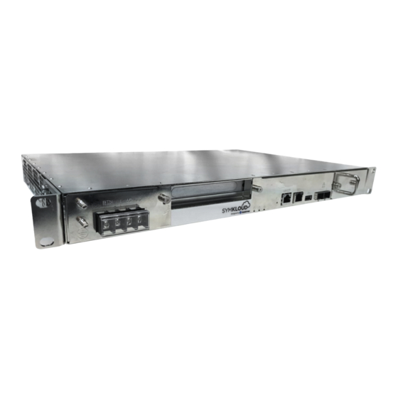
ME1100 is a 1U rackmount, short depth (300mm), Xeon D-1500 server with two 10GbE SFP+ network interfaces, optional SATA storage and a PCIe extension slot. The ME1100 server is designed for Telco Edge virtual infrastructures and could be used with Kubernetes Kontron platforms. -
Page 14: Serial Port Component Access
ME1100 Doc. Rev. 1.3 Serial Port Component Access When connecting to the serial interface, a multiplexing functionality (see Section 3.12) can establish a link with one of the following components: Baseboard Management Controller (BMC) Server (CPU) Figure 4: Serial port component access... -
Page 15: Environmental Specifications
(e.g., SFP+ Temperature, operating module, SSD and PCIe card). Kontron recommends using SFP+ and SSD modules with an industrial operating temperature range. Another limitation can result from airflow obstruction caused by fan filter clogging and failure to follow recommended side clearances. -
Page 16: Feature Summary
ME1100 Doc. Rev. 1.3 Environment Specification This product meets 8 kV contact, 15 kV air discharge using IEC 61000-4-2 Test Electrostatic discharge Method This product is designed to meet China RoHS Phase 1 (self-declaration and labeling) RoHS This product complies with EU directive 2002/96/EC (WEEE) -
Page 17: Table 6: Key Software Features
ME1100 Doc. Rev. 1.3 Feature Description Fans Hot-swappable fan tray: Fan tray contains 3 fans (standard configuration) Fan tray contains 4 fans when 2.5-in SSD option is installed Fan filter can be removed independently from the fan tray... -
Page 18: Server Components
ME1100 Doc. Rev. 1.3 Server Components 3.7.1. Front Panel Figure 5: ME1100 front view 3.7.2. Serial Port Connector Pinout Figure 6: Serial port pinout www.kontron.com // 18... -
Page 19: Led And Button Behavior
ME1100 Doc. Rev. 1.3 3.7.3. LED and Button Behavior Figure 7: Server LEDs and Button Table 7: ID and power LED behavior State (blue) Power (green) Both power inputs DOWN or out of range for normal operation One or both power inputs UP... -
Page 20: Table 8: Status Led Behavior
ME1100 Doc. Rev. 1.3 Table 8: Status LED behavior State Status (amber/red) No active error notification (normal operation) Major alarm active Amber ON Critical alarm active (service/maintenance is required) Red ON Table 9: Reset button behavior State Behavior Reset button pressed... -
Page 21: Fans And Filter
Fans and Filter The ME1100 server is equipped with a fan tray assembly comprised of fans and a filter. The filter can be pulled out by itself or the entire fan tray assembly (i.e., the fans and the filter) can be pulled out. -
Page 22: 3.7.4.1. Cooling And Thermal Management
ME1100 Doc. Rev. 1.3 3.7.4.1. Cooling and Thermal Management rated BMC. The BMC uses information collected from on-board temperature sensors in order to adjust the speed of the fans and regulate the temperature of the platform according to a PID algorithm. The temperature sensors are aggregated to provide an input value to the system temperature PID regulator, which provides a speed command for the fans. -
Page 23: Power Supply Unit
3.7.5.1. DC Power Supply Mating Cable Preparation Kontron suggests using crimp lugs (ring or spade terminal, straight, isolated, UL94V-0) on the power cables. Connect the appropriate cable to the appropriate polarity. Read the power safety warnings in Sections 1.1 and 1.2 before handling the power supply units. -
Page 24: Figure 11: Dc Power Supply Cable Preparation And Connection
Kontron suggests the following wire gauges for -48V DC and RTN: 14 AWG or 12 AWG. Kontron suggests installing the terminals so the wires connected to the -48V DC and RTN terminal blocks go up toward the top of the chassis. -
Page 25: Pcie Add-In Card
ME1100 Doc. Rev. 1.3 3.7.6. PCIe Add-in Card A PCIe add-in card can be installed in the server as an option. The PCIe add-in card maximum form factor is full- height, three-quarter length. To install a PCIe add-in card: Remove the top cover by unscrewing the 4 screws in the back and sliding the cover off toward the rear. -
Page 26: Figure 14: Pcie Riser Card And Front Plate Adaptor Assembly
ME1100 Doc. Rev. 1.3 Install the PCIe riser card onto the PCIe add-in card as shown in Figure 14. Mount the front plate adaptor onto the PCIe add- -bracket as shown in Figure 14. Fasten the front plate adaptor screw to the L-bracket (6 lbf·in torque) as shown in Figure 14. -
Page 27: Figure 15: Pcie Add-In Card Installation In Me1100
ME1100 Doc. Rev. 1.3 Figure 15: PCIe add-in card installation in ME1100 Figure 16: Assembled PCIe card Reinstall the top cover by sliding it from back to front, and then fasten the 4 screws (4 lbf·in torque). www.kontron.com // 27... -
Page 28: Optional 2.5-In Ssd
ME1100 Doc. Rev. 1.3 3.7.7. Optional 2.5-in SSD Up to four 2.5-in SSDs can be installed in the server as an option. To install 2.5-in SSDs: Remove the top cover by unscrewing the 4 screws in the back and sliding the cover off toward the rear. -
Page 29: Figure 18: Ssd Carrier Bracket Insertion
ME1100 Doc. Rev. 1.3 Figure 18: SSD carrier bracket insertion Figure 19: SSD carrier bracket attachment Reinstall the top cover by sliding it from back to front, and then fasten the 4 screws (4 lbf·in torque). www.kontron.com // 29... -
Page 30: Typical Power Consumption
SFP+ network connection (SFP+ port 2 in Figure 5) (the BMC is using NC-SI, sideband traffic, to communicate with the network). A third way to access it is from the CPU, via the KCS interface, using the ipmitool application provided by Kontron. The BMC implements the IPMI standard for management:... -
Page 31: Pci Mapping
ME1100 Doc. Rev. 1.3 PCI Mapping Table 15: PCI mapping Bus:Device. Vendor ID Device ID Component Description Function Intel Corporation Xeon E7 v4/Xeon E5 v4/Xeon 00:00.0 8086 6F00 Host Bridge E3 v4/Xeon D DMI2 (rev 03) Intel Corporation Xeon E7 v4/Xeon E5 v4/Xeon 00:01.0... -
Page 32: Mac Addresses
ME1100 Doc. Rev. 1.3 Bus:Device. Vendor ID Device ID Component Description Function QuickData Technology Register DMA Channel 3 Ethernet Intel Corporation Ethernet Connection X552 03:00.0 8086 15AC Controller 10GbE Ethernet Intel Corporation Ethernet Connection X552 03:00.1 8086 15AC Controller 10GbE Slot for PCIe Add- 05:00.0... -
Page 33: Interfaces
The IP addresses of the BMC must be in different subnets in order to avoid potential conflicts. The default IOL IP addresses are set to be static and are shown in the following figure and table. Figure 20: Default IP addresses in an ME1100 server Table 17: Default IP addresses IOL1 FRU0 192.168.0.2, netmask 255.255.255.0... -
Page 34: Figure 21: Diagram Of Interface Paths With A Serial Console Connection
ME1100 Doc. Rev. 1.3 Figure 21: Diagram of interface paths with a serial console connection *Default redirection is set to CPU 1 at system power up. The serial interface of the server includes a multiplexing functionality that can establish a link with each component through a series of hotkeys (Figure 21). -
Page 35: Table 18: Default Usernames And Passwords
Figure 22: Diagram of interface paths with a management networking connection Terminal emulator software such as PuTTY can be used. The Kontron ipmitool package can be downloaded from Symkloud.com. Kontron recommends using the ipmitool package from its website and not the open source version. -
Page 36: Description Of Interface Access Methods
, an operating system has to be installed. Redirection to the serial port must be configured in the OS (e.g., console=ttyS0, 115200n8). If the system delivered has an OS installed by Kontron, then the console redirection will be enabled by default. -
Page 37: Paths To The Me1100 Embedded Ipmitool Shell
Console redirection enabled in OS (e.g., 115200, ttyS0) or BMC of the ME1100 server BIOS is available Paths to the ME1100 embedded IPMITOOL shell Paths to the embedded IPMITOOL shell Path Main reasons for use Prerequisites Initial configuration ... -
Page 38: Getting Started
ME1100 Doc. Rev. 1.3 Getting Started Connect the Power Supply 5.1.1. DC Power Supply Connect the chassis ground to one of the ground lugs located on the faceplate. Connect appropriately rated cables from an external power source to each power supply input on the front of the unit. -
Page 39: Log In To The Bmc/Fru0 Of The Me1100
Default credentials are admin/admin. Multiple methods can be used to configure the management network of the ME1100. The following configuration steps use the serial console multiplexing feature of the platform. Please refer to Appendix C for all available methods. -
Page 40: Configure And Set The Ip Address Of Bmc/Fru0 (Static Or Dhcp)
ME1100 Doc. Rev. 1.3 Configure and Set the IP Address of BMC/FRU0 (Static or DHCP) Configure and set the IP address, the netmask and the gateway (optional for a static IP) of IOL1 FRU0 (0x20) and IOL2 FRU0. Choose Option 1 for a static IP or Option 2 for a DHCP IP. -
Page 41: Verify Bmc/Fru0 Network Configuration
ME1100 Doc. Rev. 1.3 Verify BMC/FRU0 Network Configuration Check the following configurations: IP address source (static or DHCP), IP address, subnet mask, default gateway IP and 802.1q VLAN ID. The results shown in the table below are for a static IP. -
Page 42: Optional Configurations, Monitoring And Operation
Note that because the ME1100 activates automatically on system power-up, there should be no reason to target FRU0 with power control commands unless the ME1100 needs to be powered down or control over the power states of the CPU is required. -
Page 43: Chassis Id Led Control
ME1100 Doc. Rev. 1.3 To reset the CPU: IPMITOOL From the IPMITOOL prompt of the BMC (FRU0) of the targeted server: ipmitool> power reset RemoteComputer_OSPrompt:~# ipmitool -I lanplus -H <ME1100_FRU0_IP> -U admin -P admin power reset Chassis ID Led Control... -
Page 44: Os Installation
ME1100 Doc. Rev. 1.3 To change the boot order temporarily: CPU serial console, IPMITOOL Perform a CPU reset (see Section 6.1) From the CPU serial console: 2.1) Press [Del] or [F2] when prompted to enter the BIOS setup menu Select the Save & Exit tab... -
Page 45: Disable Remote Management Using The Ipmi Protocol
ME1100 Doc. Rev. 1.3 Disable Remote Management Using the IPMI Protocol To disable the IPMI access through one of the interfaces, instruct the BMC not respond to IPMI commands over that interface: IPMITOOL From the IPMITOOL prompt of the BMC (FRU0) of the targeted server: ipmitool>... -
Page 46: Performing Updates
ME1100 Doc. Rev. 1.3 Performing Updates The ME1100 firmware components are updated via IPMITOOl using HPM package provided by Kontron. Both can be downloaded from Symkloud.com. All BIOS settings, including the boot order, are reset to their default value after a BIOS upgrade. -
Page 47: Appendix A: Sensor List
Appendix A: Sensor List This list does not cover PCIe Add-in Card sensors which are specific to design implementation. The following tables contain information on the sensors of the ME1100 server. Table 20 provides detailed information on the sensors described in blue in Table 19. - Page 48 ME1100 Doc. Rev. 1.3 Sensor Sensor type Reading Description Event offset name code type code Vcc+1.8V +1.8V 10GbE PHY See IPMI v2.0 table 42-2 for (Threshold (Voltage) supply voltage threshold based event Based) +2.5V DDR4 memory See IPMI v2.0 table 42-2 for...
- Page 49 ME1100 Doc. Rev. 1.3 Sensor Sensor type Reading Description Event offset name code type code See IPMI v2.0 table 42-2 for Fan1:Speed 04h (Fan) (Threshold Fan 1 RPM threshold based event Based) See IPMI v2.0 table 42-2 for Fan2:Speed 04h (Fan)
- Page 50 ME1100 Doc. Rev. 1.3 Sensor Sensor type Reading Description Event offset name code type code Ver Change BIOS Firmware See IPMI v2.0 table 42-3, Sensor (Version (Sensor BIOS Change Detection type code 2Bh for sensor definition Change) Specific) Only offset 0,1 are used...
-
Page 51: Table 20: Detailed Information For Kontron Oem Firmware Info
ME1100 Doc. Rev. 1.3 Table 20: Detailed information for Kontron OEM Firmware Info Event/reading Sensor specific Sensor name Sensor type Event trigger type code offset Fan Presence 04h (Fan) 00h Fan1 0 = State Deasserted Fan Fault OEM Kontron 01h Fan2... - Page 52 ME1100 Doc. Rev. 1.3 Event/reading Sensor specific Sensor name Sensor type Event trigger type code offset Event Data 2: Reset Type 00h: Warm reset State Asserted 01h: Cold reset / State 02h: Forced Cold [ Warm reset reverted to Deasserted...
- Page 53 ME1100 Doc. Rev. 1.3 Event/reading Sensor specific Sensor name Sensor type Event trigger type code offset Event Data2: The ID of the first sensor from the aggregation that caused the fault. Event Data3: Not used Sensor Aggregation List (FRU0): ID - Sensor Name...
-
Page 54: Appendix B: Ipmi Command List
ME1100 Doc. Rev. 1.3 Appendix B: IPMI Command List Table 21 lists the commands that are supported and unsupported by the FRU0. Table 21: Supported and unsupported commands for FRU0 Command ME1100 (FRU0) IPM Device "Global" Commands (NetFN/LUN 06h/0h) Get Device ID (01h) - Page 55 ME1100 Doc. Rev. 1.3 Command ME1100 (FRU0) Set User Access (43h) Supported Get User Access (44h) Supported Set User Name (45h) Supported Get User Name (46h) Supported Set User Password (47h) Supported Master Write-Read (52h) Supported Get Channel Cipher Suites (54h)
- Page 56 ME1100 Doc. Rev. 1.3 Command ME1100 (FRU0) Set Last Processed Event ID (14h) Supported Get Last Processed Event ID (15h) Supported Alert Immediate (16h) Unsupported PET Acknowledge (17h) Unsupported Sensor Device Commands (NetFN/LUN 04h/0h) Get Device SDR Info (20h) Supported...
- Page 57 ME1100 Doc. Rev. 1.3 Command ME1100 (FRU0) Get SEL Info (40h) Supported Get SEL Allocation Info (41h) Supported Reserve SEL (42h) Supported Get SEL Entry (43h) Supported Add SEL Entry (44h) Supported Partial Add SEL Entry (45h) Unsupported Delete SEL Entry (46h)
- Page 58 ME1100 Doc. Rev. 1.3 Command ME1100 (FRU0) Get Upgrade Status (34h) Supported Activate Firmware (35h) Supported Query Self-Test Results (36h) Supported Query Rollback Status (37h) Supported Initiate Manual Rollback (38h) Supported www.kontron.com // 58...
-
Page 59: Appendix C: Additional Options To Configure Iol Interfaces
Using CPU/Operating System (KCS) (IOL 1 and IOL 2) a) Install OS with open IPMI KCS support. b) Install Kontron's version of ipmitool. c) Configure IOL using LAN commands. Configure and set the IP address, the netmask and the gateway (optional for a static IP). Choose Option 1 for a static IP or Option 2 for a DHCP IP. -
Page 60: Table 22: Default Ip Addresses
IOL1 FRU0, connect the cable in the SFP+ 2 port and replace lan set 2 by lan set a) Install Kontron's version of ipmitool on a remote computer. b) Connect a cable in the MNGT port (must be configured and accessible from a remote computer) (see Figure 23). -
Page 61: Appendix D: User Application Providing Feedback To Bmc
ME1100 Doc. Rev. 1.3 Appendix D: User Application Providing Feedback to BMC The ME1100 allows customers to integrate their capabilities. This interaction takes place at a lower level than with IPMI commands. Three main tasks can be achieved: Control the Power LED to indicate system has completed booting (no blink status) ... - Page 62 ME1100 Doc. Rev. 1.3 Bash #!/bin/sh # Kontron Canada Inc. # ME1100_UserAppMon.sh # Demo script of the application LED control and # temperatures monitoring # by directly setting the FPGA registers #Stop the green LED blinking: #(write the value 0x01 to the port 2592) printf "\x01"...
- Page 63 ME1100 Doc. Rev. 1.3 C application demo using FPGA registers For a demo closer to the look and feel of a customer's application, the following C source file has to be transferred and compiled on the CPU (example provided on a CentOS operating system).
- Page 64 Entering manual IPMI commands in the OS prompt Stop LED blinking: COMMAND PURPOSE root@ME1100-BMC:~# ipmitool -v raw 0x3e 0x20 0xc4 0 Command to stop LED blinking where 0xc4 is the control-state and 0 the only possible parameter value. Running PICMG GetDeviceLocator...
- Page 65 Check the green Power LED on the faceplate. It should have stopped blinking. Set user-reported temperatures: COMMAND PURPOSE root@ME1100-BMC:~# ipmitool sensor | grep Temp | tail -n 4 Display current temperature Temp PCIe | na| degrees C| na | 0.000 | -1.000| 0.000 | thresholds.
- Page 66 ME1100 Doc. Rev. 1.3 #(write the value 0x00 to the control-state #0xc4) ipmitool raw 0x3e 0x20 0xc4 0 2> /dev/null while true # Here the customer has to add the means to read the actual temperatures from the PCIe, M.2 and SFPs) # …...
- Page 67 ME1100 Doc. Rev. 1.3 Setting sensor "Temp SFP 1" Upper Critical threshold to 30.000 Setting sensor "Temp SFP 1" Upper Non-Recoverable threshold to 50.000 [root@CentOS73 ~]# ipmitool sensor thresh "Temp SFP 2" upper Set upper threshold for SFP2 10 30 50 Temperature.
- Page 68 BMC's status: observing timeouts on these commands is an indication that the BMC is rebooting. Setting BMC time For safety purposes, the ME1100 BMC does not use a battery to store time. The NTP is provided as solution for BMC time synchronization.
- Page 69 ME1100 Doc. Rev. 1.3 NOTE: Each time the BMC restarts (e.g. after a version update), its time is reset and needs to be updated by the user. b) The sub-function OEMAP_NTP_SET_OFFSET (03h) allows the user to set the time by providing 4 data bytes with the epoch time requested.
- Page 70 ME1100 Doc. Rev. 1.3 Appendix E: Several useful IPMI commands are implemented by Kontron as OEM commands. (The ipmitool version should be at least 1.8.13-K12 to support the NTP OEM commands.) Below is a short list of the available commands (00 = Linear and 01 = Circular):...
- Page 71 ME1100 Doc. Rev. 1.3 About Kontron Kontron, a global leader in embedded computing technology and trusted advisor in IoT, works closely with its customers, allowing them to focus on their core competencies by offering a complete and integrated portfolio of hardware, software and services designed to help them make the most of their applications.
Need help?
Do you have a question about the ME1100 and is the answer not in the manual?
Questions and answers