
Subscribe to Our Youtube Channel
Related Manuals for Kontron KISS 1U Short V2 KTQM87-A


Summary of Contents for Kontron KISS 1U Short V2 KTQM87-A
- Page 1 » User’s Guide « KISS 1U Short V2 KISS 1U Short V2 KTQM87-A User’s Guide (Version 1.0) 1057-0668 www.kontron.com...
-
Page 2: Table Of Contents
9.1. AC-Power Cord Connection ........................22 9.2. Operating System and Hardware Components Drivers .................. 23 10. Maintenance and Prevention ........................ 24 10.1. Replacing the Lithium Battery ......................24 10.2. Replacing the System Fans ........................24 10.3. Cleaning the Filter Mat ........................25 www.kontron.com... -
Page 3: Table Of Figures
Fig. 19: Detail with opened slide brackets for PCI card slot ................. 20 Fig. 20: KISS 1U Short V2 AC input connector ....................22 Fig. 21: Detail of the front side - Location of the filter mat ................. 25 www.kontron.com... - Page 4 Fig. 25: Attaching the inner side of the slide rail ..................... 27 Fig. 26: KISS 1U Short V2 with slide rails in pulled-out position ................27 Fig. 27: KISS 1U Short V2 with slide rails ......................27 Fig. 28: Assembling the “Telescopic Rail” set ....................28 www.kontron.com...
-
Page 5: Introduction
Kontron does not accept any liability for any printing errors or other inaccuracies in the manual unless it can be proven that Kontron is aware of such errors or inaccuracies or that Kontron is unaware of these as a result of gross negligence and Kontron has failed to eliminate these errors or inaccuracies for this reason. -
Page 6: Symbols Used In This Manual
This symbol indicates that the product or parts thereof may be damaged if the corresponding warning notices are not observed. This symbol indicates general information about the product and the user manual. This symbol indicates detail information about the specific product configuration. This symbol precedes helpful hints and tips for daily use. www.kontron.com... -
Page 7: Important Instructions
In the event of damage to the device caused by failure to observe the included document “General Safety Instructions for IT Equipment”, the hints in this manual or eventually the warning signs label on the device, Kontron shall not be required to honor the warranty even during the warranty period and shall be exempted from the statutory accident liability obligation. -
Page 8: General Safety Instructions For It Equipment
If the enclosure of such a drive is opened, invisible laser radiation is emitted. Do not allow yourself to be exposed to this radiation. The laser system meets the code of Federal Regulations 21 CFR, 1040 for the USA and the Canadian Radiation Emitting Devices Act, REDR C 1370. www.kontron.com... -
Page 9: Electrostatic Discharge (Esd)
The lithium battery type must be UL recognized. Do not dispose of lithium batteries in general trash collection. Dispose of the battery according to the local regulations dealing with the disposal of these special materials, (e.g. to the collecting points for dispose of batteries). www.kontron.com... -
Page 10: Electromagnetic Compatibility
5.3. EMC Compliance (Canada) The method of compliance is self-declaration to Canadian standard ICES-003: (English): This Class B digital apparatus complies with the Canadian ICES-003. (French): Cet appareil numérique de la classe B est conforme à la norme NMB-003 du Canada. www.kontron.com... -
Page 11: Scope Of Delivery
“y” is replaced by a single letter (A through Z) representing the power supply installed in the system. Note for the equipped PSU (Power Supply Unit): A: corresponds to the systems with a wide range AC power supply (100-240 V, 270 W) www.kontron.com... -
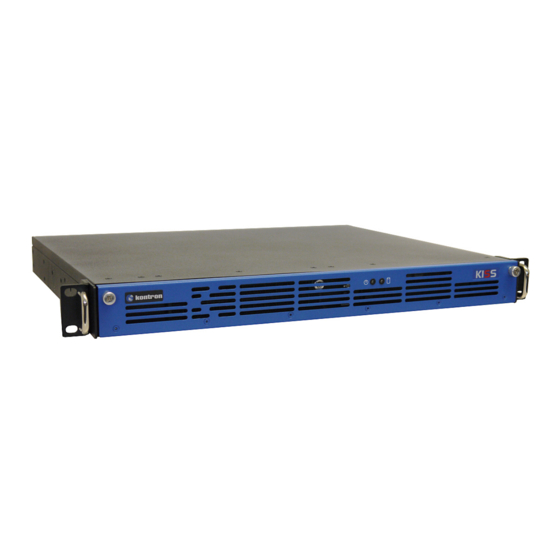
Page 12: Product Description
7. Product Description KISS 1U Short V2 extends the range of Kontron’s product family– KISS -. It is a 1U (19") platform equipped with a motherboard and can be equipped with up to two drive bays (refer to the “Configuration Guide” on our web site). The flexible hardware system configuration and robust design with excellent mechanical stability provides the KISS 1U Short V2 platform with the necessary characteristics for a computer, which is suitable for use in harsh industrial environments. - Page 13 10 Fixing brackets for the cover on the rear side 5 Fixing brackets for the cover on the front side 11 PCIe-slot for expansion card (max. 25 cm (10") card length) 6 Fan slide-in module (equipped with two fans) 12 Slide bracket with fixing screws www.kontron.com...
-
Page 14: Front Side
(shown with one DVD drive installed) 3 Filter mat holder with captive knurled screws 8 D2: 3.5"externally accessible drive bay 4 2x USB 2.0 (shown with optional KISS-Stor Slim SATA RAID 1 5 LED indicators (power LED and HDD LED) Solution installed) www.kontron.com... -
Page 15: Interfaces On The Front Side
Depending on the configuration ordered, your KISS 1U Short V2 can be equipped with up to two externally accessible drives: D1 (1x 5.25" Slim-line drive bay) and D2 (1x 3.5" drive bay) (refer to Fig. 8, pos. 7 and pos. 8). www.kontron.com... -
Page 16: Rear Side
7.2.1. Interfaces of the Motherboard on the Rear Side Information and technical data can be found in the corresponding motherboard manual. You can download the relevant motherboard manual for your system configuration from our web site at www.kontron.com by selecting the product name. 7.2.2. Power Supply Unit The power supply unit (PSU) is placed on the rear side of the KISS 1U Short V2 platform (Fig. -
Page 17: Side View
(Fig. 12, pos. 3) will be inserted properly into the corresponding retaining brackets for the cover ( Fig. 5, pos. 10) on the rear side of the chassis. Fig. 12: Inside of the cover with fixing brackets 1 Captive knurled screws 3 3x front fixing brackets 2 Insulation foil (Makrolon) 4 Inside of the cover www.kontron.com... -
Page 18: Fan Module
2 Captive knurled screws of the fan module 3 Two fans per fan module 4 Fan connection The KISS 1U Short V2 platform should only be operated with a functioning fan module Defective components should only be replaced by Kontron. www.kontron.com... -
Page 19: Assembly, Disassembly
1. Turn off your system and disconnect the power cord from the mains. 2. Loosen the fastening screws on the rear side of the unit that secure the cover. Fig. 14: Loosening the three fastening screws on the rear side of the KISS 1U Short V2 system www.kontron.com... - Page 20 4 Fastening screw for the slide bracket (card slot bracket) 6. Move the slide bracket to the right. The slot bracket is disengaged now and can be removed from the system. Fig. 18: Detail: Rear side with slide bracket (opened) www.kontron.com...
- Page 21 12. Close the device and secure the cover with the fastening screws (Fig. 10, Fig. 12, pos. 1) on the rear side. pos. 3 When closing the cover, make sure that the cover fixing brackets (Fig. 12, ) slide into the corresponding retaining brackets ( Fig. 5, pos. 6) of the chassis. www.kontron.com...
-
Page 22: Instruction For Installation In A 19" Cabinet
If further stabilization is necessary, then bolt the 19" industrial cabinet to the floor or anchor it on the wall. The voltage feeds must not be overloaded. Adjust the cabling and the external overcharge protection to correspond with the electrical data indicated on the type label. The type label is located on right side of the unit. www.kontron.com... -
Page 23: Starting Up
The power cord is used as a disconnecting device (the unit is only completely disconnected from the mains, when the power cord is disconnected either from the mains or the unit). Therefore, the outlet of the AC power source must be located near to the device and be easily accessible. www.kontron.com... -
Page 24: Operating System And Hardware Components Drivers
The terms and condition for using the pre-installed operating systems are defined in the document „MICROSOFT SOFTWARE LICENSE TERMS“. This document can be downloaded from our web site www.kontron.com by selecting the product name/tab Downloads/Windows. If you have ordered your system without a pre- installed operating system, you have to install the operating system and the corresponding drivers for the ordered computer configuration (optional hardware components). -
Page 25: Maintenance And Prevention
4. Make sure that you insert the battery the right way around. The plus pole must be on the top! 5. The lithium battery must be replaced with an identical battery or a battery type recommended by Kontron. The Lithium battery type must be UL listed. -
Page 26: Cleaning The Filter Mat
1. Open the front access door (Fig. 6, pos. 4). 2. Loosen the knurled screw (Fig. 21, pos. 3) that secure the filter mat holder with the air filter mat to the chassis. 3. Pull out the filter mat holder (Fig. 21, pos. 3) into the marked direction. www.kontron.com... - Page 27 7. Tighten the knurled screws to secure the filter mat holders to the chassis. When inserting the filter mat, ensure that the denser side of the mat is facing the fans. Defective components may be replaced only by Kontron original spare parts. Part number of the filter mat: 1017-2544...
-
Page 28: Slide Rails (Option)
KISS 1U Short V2 – User’s Guide (Version 1.0) 11. Slide Rails (Option) Kontron offers slide rails for installing the KISS 1U Short V2 platform into a 19" industrial cabinet. These can be ordered under: “Slide rails” - Set No.: 3-A260-0244. -
Page 29: Slide Rails Accessories And Assembling
2x bar nut kits 8x M4x6 flathead screws For assembling refer to Fig. 28. Fig. 28: Assembling the “Telescopic Rail” set Short brackets are usually used at the front of the chassis and long brackets at the rear. www.kontron.com... -
Page 30: Main Specifications
The corresponding “Configuration Guide” and the manual of the installed board can be downloaded from our web site at www.kontron.com by selecting the product name. 12.1. Electrical Specifications The electrical specification you can read off on the type label of your KISS 1U Short V2 platform. -
Page 31: Mechanical Specifications
15 G, 30 ms duration, half sine Operating Shock Horizontal 10 G, 45 ms duration , half sine Storage/Transit Shock 30 G, 11 ms, duration, half sine Operating Vibration 5 – 500 Hz, 1.0 G Storage / Transit Vibration 5 – 500 Hz, 2.0 G www.kontron.com... -
Page 32: Ce Directives And Standards
UL60950-1/ CSA C22.2- No. 60950-1-7 CB Scheme CB Certification Harmonized Standards Generic emission standard for industrial environments (Emission): EN 61000-6-4:2007 Generic standards - Immunity for industrial environments (Immunity): EN 61000-6-2:2005 U.S.A. FCC 47 CFR Part 15, Class B KANADA ICES-003, Class B www.kontron.com... -
Page 33: Standard Interfaces - Pin Assignments
GND (ML Lane 2) Lane 2 (n) Lane 3 (p) GND (ML Lane 3) Lane 3 (n) AUX SEL# Pull-down to GND AUX CH (p) GND (AUX CH) AUX CH (n) Hot Plug 3.3V (DDC EEPROM power GND (GND_DDC) 500 mA fused www.kontron.com... -
Page 34: Usb 2.0 Port
Type A Version 2.0 Data- Data+ 13.1.4. USB 3.0 Port Pin Signal Name 9-pin USB Socket Type A Version 3.0/2.0 USB 2.0 contact pins USB 3.0 contact pins VCC, StdA_SSRX- fused (900 mA max.) StdA_SSRX+ Data- GND_DRAIN Data+ StdA_SSTX- StdA_SSTX+ www.kontron.com... -
Page 35: Technical Support
Be ready to explain the nature of your problem to the service technician. If you have questions about Kontron or our products and services, you can reach us by the above-mentioned telephone number and on e-mail address or at: www.kontron.com...
Need help?
Do you have a question about the KISS 1U Short V2 KTQM87-A and is the answer not in the manual?
Questions and answers