Sign In
Upload
Manuals
Brands
Kontron Manuals
Server
KISS 2U V4 ADL
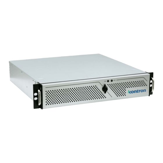
Kontron KISS 2U V4 ADL Manuals
Manuals and User Guides for Kontron KISS 2U V4 ADL. We have
1
Kontron KISS 2U V4 ADL manual available for free PDF download: User Manual
Kontron KISS 2U V4 ADL User Manual (76 pages)
Brand:
Kontron
| Category:
Server
| Size: 3 MB
Table of Contents
Symbols
6
For Your Safety
7
High Voltage Safety Instructions
7
Special Handling and Unpacking Instruction
7
Lithium Battery Precautions
8
General Instructions on Usage
8
Quality and Environmental Management
8
Disposal and Recycling
8
WEEE Compliance
8
Table of Contents
9
List of Tables
11
List of Figures
12
1/ Introduction
13
Figure 1: KISS 2U V4 ADL
13
2/ General Safety Instructions
15
Instructions Générales de Sécurité
16
Electrostatic Discharge (ESD)
17
Grounding Methods
17
Instructions for the Lithium Battery
18
Operation of Laser Source Devices
19
3/ Shipment and Unpacking
20
Packaging
20
Unpacking
20
Scope of Delivery
20
Accessories and Spare Parts
20
Table 1: Scope of Delievy
20
Table 2: Accessories and Spares Parts
20
Product Identification Type Label
21
Figure 2: Type Label Examples
21
4/ Product Features
22
Front Panel
22
Figure 3: Front Panel
22
Front Flap
23
Drive Bays
23
Figure 4: Front Flap
23
Handle Brackets
24
Fans Assembly
24
Figure 5: Handle Brackets
24
Power Button
25
Power LED and HDD LED
25
Table 3: Power LED and HDD LED
25
Figure 6: Power Button
25
Figure 7: LED Indicators
25
USB Ports
26
Figure 8: USB 3.2 Gen 1 Port
26
Rear Panel
27
Figure 9: Rear Panel (Low Profile)
27
Display Port (DP)
28
Table 4: Display Resolution
28
Table 5: Display Order Priority
28
Figure 10: Rear Panel (Riser Card)
28
Usb 3.2
29
Lan
29
Serial Ports (COM)
30
Audio
30
Power Supply Unit
30
Table 6: Redundant PSU LED Description
31
Figure 11: Single PSU (400 W)
31
Figure 12: PSU, 550 W (Redundant)
31
Potential Equalization Stud
32
PCIE/PCI Expansion Card Slots
32
Side
33
Cover
33
Figure 13: Left Side
33
Figure 14: Right Side
33
Figure 15: Cover Top Side (Low Profile)
34
Figure 16: Cover Underside (Low Profile)
34
System Configuration
35
Figure 17: Example of KISS 2U V4 ADL Configuration
35
5/ System Expansion
36
Before Expanding
36
Mass Storage (Internal)
36
Drive Bays (Front Panel or Internal)
36
Table 7: Mass Storage (Internal)
36
Table 8: Drive Bays
36
Expansion Cards
37
Reference Pcie Expansion Cards
37
Table 9: Pcie/Pci Expansion Cards Slot Allocation
37
Table 10: Reference KISS 2U V4 ADL Pcie Expansion Cards
37
6/ Thermal Management
39
Active Cooling
39
Temperature Sensor
39
Minimum Thermal Clearance
39
Third Party Components
40
7/ Assembly
41
Before Assembling the Product
41
Opening and Closing the Cover
41
Installing and Removing Pcie/Pci Expansion Cards (Low Profile Variant)
42
Figure 18: Push Button (Left and Right Side)
42
Installing and Removing Pcie Expansion Cards (Riser Card Variant)
43
Figure 19: Installing Low Profile Expansion Cards
43
Installing and Removing the Handle Brackets
44
Figure 20: Installing Riser Card Expansion Cards
44
Installing and Removing the Front Flap
45
Installing the Rubber Feet
45
Installing Slide Rails
45
8/ Mounting
46
Before Mounting
46
Mounting on a Desktop
47
Mounting in a 19" Industrial Rack Cabinet
47
9/ Starting up
49
Before Starting
49
Connecting the Power Supply
49
Figure 21: Input Power Socket
49
Connecting to the Redundant Power Supply (Option)
50
Switching on
50
Figure 22: Redundant Power Sockets
50
Figure 23: Power Button
50
Operating System and Hardware Component Drivers
51
10/ Bios
52
Starting the BIOS
52
BIOS Setup Menus
52
BIOS Navigation
53
BIOS Update
53
Updating the BIOS
53
Table 11: Navigation Hot Keys in the Legend Bar
53
Figure 24: BIOS FTP Server
53
Recover BIOS
54
11/ Product Specification
55
Block Diagram
55
Figure 25: Block Diagram KISS 2U V4 ADL (Low Profile)
55
Figure 26: Block Diagram KISS 2U V4 ADL (Riser Card)
56
Hardware Specification
57
Table 12: Hardware Specification
57
Software Specification
58
Power Specification
58
Table 13: Software Specification
58
Table 14: Electrical Specification
58
Environmental Specification
59
Table 15: Environmental Specification
59
Mechanical Specification
60
Compliance
60
Table 16: Mechanical Specification
60
Table 17: CE Compliance
60
Table 18: International Compliance
61
12/ Standard Interfaces- Pin Assignment
62
DP Port Pin Assignment
62
USB 3.2 Gen 2/1 Pin Assignment
62
Table 19: DP V1.4A Pin Assignment
62
Table 20: USB 3.2 Gen 2 Pin Assignment
62
USB-C 3.2 Gen 2 Port Pin Assignment
63
2.5 Gbe/1.0 Gbe Pin Assignment
63
Table 21: USB 3.2 Gen 2 Type C Pin Assignment
63
Table 22: LAN (RJ45) Connector Pin Assignment
63
COM Port Pin Assignment
64
Audio Jack Connector Pin Assignment (Line-In, Line-Out, MIC-In)
64
Table 23: RS232 Connector Pin Assignment
64
Table 24: Audio Jack Pin Assignment
64
M.2 Key M (NVME SSD) Socket Pin Assignment
65
Table 25: M.2 Key M Socket Pin Assignment
65
Jumpers
66
Recover BIOS Jumper
66
Table 26: Recover BIOS Jumper
66
Figure 27: Recover BIOS Jumper
66
13/ Maintenance and Prevention
67
Before Maintaining the Product
67
Cleaning the Product
67
Cleaning the Filter Pad
67
Replacing the System Fans
68
Figure 28: Removing the Filter Pad
68
Replacing the Lithium Battery
69
Figure 29: Removing a System Fan
69
Replacing the Internal 2.5" SSD Drive
70
Figure 30: Lithium Battery (CR2032)
70
Replacing a M.2 SSD Module
71
Replacing a Faulty Redundant PSU Unit
71
14/ Technical Support
73
Returning Defective Merchandise
73
15/ Warranty
74
Limitation/Exemption from Warranty Obligation
74
List of Acronyms
75
Table 28: List of Acronyms
75
About Kontron
76
Advertisement
Advertisement
Related Products
Kontron Kiss 2U
Kontron 2-A0HC Series
Kontron KISS 2U V3
Kontron KISS 2U V2
Kontron 22201
Kontron 2-DH47-0010
Kontron MediClient 23.8"
Kontron MediClient 21.5"
Kontron KISS 1U V4 ADL
Kontron CC2800
Kontron Categories
Computer Hardware
Motherboard
Server
Industrial PC
Desktop
More Kontron Manuals
Login
Sign In
OR
Sign in with Facebook
Sign in with Google
Upload manual
Upload from disk
Upload from URL