Table of Contents

Related Manuals for Dalsa ML-FM-16K07A


Summary of Contents for Dalsa ML-FM-16K07A
- Page 1 Linea ML Multiline Cameras Monochrome / HDR CMOS ML-FM-08K30H, ML-FM-16K07A, ML-FM-16K15A, ML-HM-08K30H and ML-HM-16K30H sensors | cameras | frame grabbers | processors | software | vision solutions 03-032-20263-03 www.teledynedalsa.com...
- Page 2 Document number: 03-032-20263-03 About Teledyne DALSA Teledyne DALSA, a business unit of Teledyne Digital Imaging Inc., is an international high- performance semiconductor and Electronics Company that designs, develops, manufactures, and markets digital imaging products and solutions, in addition to providing wafer foundry services.
-
Page 3: Table Of Contents
Contents LINEA ML MULTILINE MONOCHROME / HDR CMOS CAMERAS ESCRIPTION AMERA IGHLIGHTS Key Features Programmability Applications UMBERS AND OFTWARE EQUIREMENTS ERFORMANCE PECIFICATIONS Flash Memory Size Certification & Compliance AMERA IXEL RRANGEMENT AMERA ROCESSING HAIN UPPORTED NDUSTRY TANDARDS GenICam™ Camera Link HS Data Cables &... - Page 4 Exposure Mode Sequential Adjusting Responsivity Image Response Uniformity & Flat Field Calibration Saving & Rapidly Loading a PRNU Set Only Setting Custom Flat Field Coefficients Flat Field Calibration Filter Flat Field Calibration Regions of Interest TDI S TAGE ELECTIONS AND HDR Demo Mode INNING Using Area of Interest to Reduce Image Data &...
- Page 5 Voltage & Temperature Measurement Test Patterns – What Can They Indicate? Built-In Self-Test Codes ESOLVING AMERA SSUES Communications: Image Quality Issues Power Supply Issues Causes for Overheating & Power Shut Down DECLARATIONS OF CONFORMITY FCC Statement of Conformance CE and UKCA Declaration of Conformity DOCUMENT REVISION HISTORY CONTACT INFORMATION ALES...
-
Page 6: Linea Ml Multiline Monochrome / Hdr Cmos Cameras
(LC or CX4, resolution dependent). Teledyne DALSA’s Linea ML cameras and compatible frame grabbers combine to offer a complete solution for the next generation of automatic optical inspection (AOI) systems. -
Page 7: Camera Highlights
Camera Highlights Key Features • Highly responsive multiline CMOS • 8K or 16K pixel resolution • Up to 300 kHz line rates • Very low noise • Bi-directionality with fixed optical center • Binning • Robust Camera Link HS interface •... -
Page 8: Part Numbers And Software Requirements
5.0 x 5.0 µm Camera Link HS 140 kHz x 2 HDR mode LC fiber optic (300 kHz / 150 x 2 kHz using AOI) ML-FM-16K07A-00-R 16,384 x 1 pixels 70 kHz monochrome 5.0 x 5.0 µm Camera Link HS LC fiber optic... -
Page 9: Performance Specifications
Performance Specifications Table 4: Camera Performance Specifications Specifications ML-HM-08K30H ML-FM-08K30H ML-HM-16K30H ML-FM-16K07A ML-FM-16K15A Imager Format High speed CMOS multiline sensor Resolution 8,192 x 4 pixels mono 16,384 x 4 pixels mono 16,384 x 1 pixels mono Pixel Size 5.0 µm x 5.0 µm... -
Page 10: Flash Memory Size
Operating Ranges Performance ML-FM-16K07A (ML-FM-08K30H, ML-HM-08K30H, ML-HM-16K30H) ML-FM-16K15A Random Noise < 0.3 DN rms, typical Peak Responsivity Low Responsivity Line 3 DN / (nJ / cm High Responsivity Line 18 DN / (nJ / cm 18 DN / (nJ / cm... -
Page 11: Camera Pixel Arrangement
Figure 2: ML-FM-16K07A and ML-FM-16K15A Pixel Structure The ML-FM-16K07A and ML-FM-16K15A cameras operate with a single high sensitivity line output only. There is no difference in camera operation when the scanning direction is changed. -
Page 12: Camera Processing Chain
Camera Processing Chain The diagram below details the sequence of arithmetic operations performed on the cameras sensor data, which the user can adjust to obtain an optimum image for their application. These adjustments are performed using camera features outlined in the ‘Review of Camera Performance and Features’... -
Page 13: Data Cables
The distance through which the data can be transmitted depends on the type of fiber optic used. Recommended fiber optic cables are types OM3 and OM4. OM4 is used for distances > 300 m, but also requires SFP+ transceiver module changes. Contact Teledyne DALSA Support for more information on recommended cables. Category Fiber Diameter... - Page 14 Camera Link HS cables can be bought from an OEM. OEM cables are also available for applications where flexing is present. Please refer to Teledyne DALSA’s website (www.teledynedalsa.com) for a list of recommended cable vendors and for part numbers. Each data cable is used for sending image data to and accepting command data from the frame grabber.
-
Page 15: Responsivity & Qe Plots
Responsivity & QE Plots Figure 5. Camera Spectral Responsivity Note: Responsivity values measured using 8-bit, 1x gain, single row. Figure 6. Camera Quantum Efficiency Linea ML Multiline Monochrome / HDR CMOS Cameras • 15... -
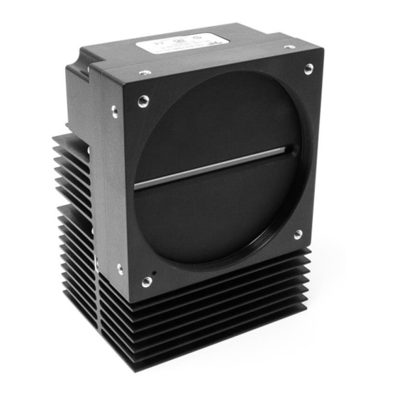
Page 16: Mechanical Drawings
Mechanical Drawings Figure 7. Linea ML-FM-8K Camera Mechanical 16 • Linea ML Multiline Monochrome / HDR CMOS Cameras... - Page 17 Figure 8. Linea ML-FM-16K Camera Mechanical Linea ML Multiline Monochrome / HDR CMOS Cameras • 17...
- Page 18 Figure 9. Linea ML-HM-16K Camera Mechanical 18 • Linea ML Multiline Monochrome / HDR CMOS Cameras...
- Page 19 Figure 10: ML-HM-08K camera mechanical Linea ML Multiline Monochrome / HDR CMOS Cameras • 19...
-
Page 20: Precautions
Precautions Read these precautions before using the camera. Confirm that the camera’s packaging is undamaged before opening it. If the packaging is damaged please contact the related logistics personnel. Do not open the housing of the camera. The warranty is voided if the housing is opened. Keep the camera’s front plate temperature in a range of 0 °C to +65 °C during operation. -
Page 21: Install & Configure Frame Grabber & Software
Install & Configure Frame Grabber & Software Because of the high bandwidth required by these cameras, we recommend a compatible Teledyne DALSA frame grabber (part numbers: OR-A8S0-FX840 (ML-FM) or OR-A8S0-PX870 (ML-HM)), or equivalent, described in detail on the teledynedalsa.com site here. -
Page 22: Camexpert Panes
CamExpert Panes CamExpert, first instance: select Camera Link HS using the Device drop-down menu. Figure 11. CamExpert Frame Grabber Control Window The CamExpert application uses panes to organize the selection and configuration of camera files or acquisition parameters. Device Selector pane: View and select from any installed Sapera acquisition device. Once a device is selected, CamExpert will only show acquisition parameters for that device. - Page 23 Control Buttons: The display pane includes CamExpert control buttons. These are: Acquisition control button: Click once to start live grab, click again to stop. Single frame grab: Click to acquire one frame from device. Trigger button: With the I/O control parameters set to Trigger Enabled, click to send a single trigger command.
-
Page 24: Setting Up For Imaging
Setting Up for Imaging Figure 12. Camera I / O Connectors: ML-FM models (left) & ML-HM models (right). Camera I / O Connectors 1) Factory use only. 2) Data and control connectors: LC or CX4 AOC. 3) LED status indicators. 4) Power and GPIO connectors: +12 V to +24 V DC, Hirose 12-pin circular. -
Page 25: Power And Gpio Connections
• When using a 12 V supply, voltage loss in the power cables will be greater due to the higher current. Use the Camera Information category to refresh and read the camera’s input voltage measurement. Adjust the supply to ensure that it reads above or equal to 12 V. Note: If your power supply does not meet these requirements, then the camera performance specifications are not guaranteed. - Page 26 Voltage & Temperature Measurement for more details. Mating GPIO Cable Assembly Teledyne DALSA makes available for purchase an optional GPIO breakout cable (12-pin Female Hirose to 13-Pos Euro Block), as shown in the following drawing. Use accessory number #CR- GENC-IOP00 to order.
- Page 27 External Input Electrical Characteristics Switching Voltage Input Level Standard Low to high High to low Input Impedance 3.3V TTL 2.1V 10K Ω External Input Timing Reference Input Level Maximum Input Minimum Pulse Input Current Maximum Signal Propagation Delay Standard Frequency Width @ 60 3.3V TTL...
-
Page 28: Establishing Camera Communications
Establishing Camera Communications When you power up the camera, observe the LED status indication on the back. The LED will indicate one of the following status conditions: LED State Description Camera not powered up or waiting for the software to start Constant Red The camera BIST status is not good. -
Page 29: Camera Performance And Features
Camera Performance and Features This section is intended to be a progressive introduction to the features of the camera, including explanations of how to use them effectively. A detailed description of all features is found in Appendix A: GenICam Commands. Synchronizing to Object Motion Acquiring Images: Triggering the Camera Related Features: ExposureMode, TriggerMode, TriggerSource,... -
Page 30: Measuring Line Rate (Trigger)
Maximum Line Rate (1 sensor line output, 8 bit) Camera Model One Fiber Optic Cable Two Fiber Optic Cables One AOC cable ML-FM-08K30H-00-R 140 kHz 280 kHz ML-FM-16K07A-00-R 70 kHz 70 kHz ML-FM-16K15A-00-R 71 kHz 143 kHz ML-HM-08K30H-00-R 300 kHz... - Page 31 Direction Change Time The direction change time between forward and reverse is < 1 ms. Figure 13. Image with incorrect scan direction Camera Performance and Features • 31...
-
Page 32: Camera Orientation
Camera Orientation The diagram below shows the orientation of forward and reverse with respect to the camera body. Note: The diagram assumes the use of a lens on the camera, which inverts the image. Figure 14: Example of Object Movement and Camera Direction (8K camera shown) The diagram shows the designated camera direction. -
Page 33: Compensating For Encoder Errors (Spatial Correction)
Compensating for Encoder Errors (Spatial Correction) See Camera Control Category in Appendix A for GenICam features associated with this section and how to use them. Related Feature: sensorLineSpatialCorrection To achieve a sharp image in the vertical direction when running the camera in TDI mode or in HDR mode it is important that the lines being used are aligned correctly. - Page 34 Object Pixel Setup for 20 µm, Encoder set at 19 µm. Forward Scanning Can be corrected with 20 / 19 = 1.05 Line Spatial Correction Object Pixel Setup for 20 µm, Encoder set at 21 µm. Forward Scanning Can be corrected with 20 / 21 = 0.95 Line Spatial Correction If there are several different camera angles and associated illumination configurations in the inspection system, a single encoder pulse will not provide the correct timing for all the cameras.
-
Page 35: Parallax Correction: Using The Camera At Non-Perpendicular Angles To The Object
Parallax Correction: Using the Camera at Non-Perpendicular Angles to the Object See Camera Control Category in Appendix A for GenICam features associated with this section and how to use them. Related Features: imageDistortionCorrectionMode, imageDistortionCorrectionAlgorithm, imageDistortionCorrectionLineSelector, imageDistortionParallaxCorrectionPixelStretch When using a camera at an angle to the objects surface, the object pixel sizes for the three arrays are slightly different—this is due to parallax. - Page 36 Image example of artifact induced by parallax at the image extremity: Camera Angle, 8k Camera, 80 mm lens, 20 µm Object Pixel, Spatial Correction =9.2, No Parallax Correction 36 • Camera Performance and Features...
-
Page 37: Establishing The Desired Response
(Timed, Sequential) ExposureMode has 2 options: Timed and Sequential. Timed is the standard exposure operation as found in Teledyne DALSA line scan cameras. For operation of sequential mode, please see the section titled Exposure Mode Sequential. See the Exposure Control Section. -
Page 38: Exposure Time Selector
Use exposureTimeSelector to select whether to set the exposure time of each row independently or all to the same value. exposureDelay is only configurable when in Sequential exposure mode. Adjusting the exposure will result in a temporary loss of LVAL (8 lines) while the sensor is re- configured. -
Page 39: Sequential Mode Application Example
Sequential Mode Application Example The Linea ML is equipped with an innovative new mode that allows each line of the sensor to be exposed in a serial sequence with a single trigger applied to the camera. This can allow an object to be imaged with various lighting condition on a single pass of the image object past the camera. -
Page 40: Exposure Mode Sequential
Exposure Mode Sequential Relevant Features: ExposureMode, ExposureTime, ExposureDelay, TriggerDelay, outputLinePulseDelay, outputLinePulseDuration Unique to the Linea ML camera is the sequential exposure mode. For each trigger entering the camera the exposure for each line can be executed separately and in a serial sequence. This allows the user to set up different lighting conditions for each line. - Page 41 The trigger signal entering the camera is routed to the sensor and also to each of the output control features. The TriggerDelay feature delays the trigger going to the sensor. This delay allows the user to turn on the LED before exposing the sensor. Each line can be delayed relative to the previous line using the ExposureDelay feature.
-
Page 42: Adjusting Responsivity
Adjusting Responsivity See the section Camera Control Category in Appendix A for GenICam features associated with this section and how to use them. Relevant Features: GainSelector, Gain It is desirable for camera performance to always use the maximum exposure time possible based on the maximum line rate of the inspection system and any margin that may be required to accommodate illumination degradation. -
Page 43: Saving & Rapidly Loading A Prnu Set Only
Settings and then select Miscellaneous > Current PRNU to download / upload a file. The file format is described in the document 03-084-20133 Linea ML Binary File Format, which can be obtained from Teledyne DALSA Technical Support. This document also includes Excel spread sheet examples. -
Page 44: Flat Field Calibration Filter
Flat Field Calibration Filter See the section Flat Field Category in Appendix A for GenICam features associated with this section and how to use them Related Feature: flatfieldCorrectionAlgorithm If a sheet of material is being used as a white target, it must be completely free of blemishes and texture. -
Page 45: Tdi Stage Selections And Full Well
TDI Stage Selections and Full Well See the section Camera Control Category in Appendix A for GenICam features associated with this section and how to use them Relevant Features: sensorTDIModeSelection, sensorTDIStagesSelection, sensorFullWellMode The camera’s sensor has 3 high-responsivity lines. These line scans be summed to further increase the responsivity. -
Page 46: Hdr Demo Mode
HDR Demo Mode In planar mode, the camera can be configured to output sensor row 0 and 1 separately. Under the same conditions, the row 1 is 4x more responsive than the row 0. The contrast ratio does not always have to be 4:1, it can be varied depending on the contrast of the object. The user can change the ratio by changing the exposure time and/or gain. -
Page 47: Binning
Binning See the section Image Format Control Category in Appendix A for GenICam features associated with this section and how to use them Related Features: Horizontal Binning, Vertical Binning In certain applications, lower image resolution may be acceptable if the desired defect detection can still be achieved. -
Page 48: Using Area Of Interest To Reduce Image Data & Enhance Performance
Using Area of Interest to Reduce Image Data & Enhance Performance See the section Image Format Control Category in Appendix A for GenICam features associated with this section and how to use them Related Features: AOI Count, AOI Selector, AOI Offset, AOI Width If the camera’s field of view includes areas that are not needed for inspection (also refer to the description in the Flat Field Calibration Region of Interest section) then the user may want to ignore this superfluous image data. -
Page 49: Rules For Setting Areas Of Interest
Look Up Table to upload a file. The file format is described in 03-084-20133 Linea ML Binary File Format which can be obtained from Teledyne DALSA Technical Support. This document also includes Excel spread sheet examples. Camera Performance and Features... -
Page 50: How To Generate Lut With Camexpert
How to Generate LUT with CamExpert CamExpert can also be used to create a LUT file. The camera uses a 12-bit in / 12-bit out LUT (even if the camera is outputting an 8-bit image). CamExpert can be configured to create a 12-bit in / 16-bit out LUT - the camera will convert it to the required format. -
Page 51: Adjusting Responsivity And Contrast Enhancement
Adjusting Responsivity and Contrast Enhancement See the section Camera Control Category in Appendix A for GenICam features associated with this section and how to use them. Related Features: Gain Selector, Gain, Offset It is best for camera performance to always use the maximum exposure time possible based on the maximum line rate of the inspection system and any margin that may be required to accommodate illumination degradation. -
Page 52: Changing Output Configuration
Changing Output Configuration Pixel Format See the section Image Format Control Category in Appendix A for GenICam features associated with this section and how to use them Related Feature: Pixel Format The camera can output video data as 8-bit or 12-bit. The Mono8 Pixel Format are selected when the user wants to process image data as one, two, or three separate image planes. -
Page 53: Saving & Restoring Camera Setup Configurations
Saving & Restoring Camera Setup Configurations See the section Camera Information Category in Appendix A for GenICam features associated with this section and how to use them Related Features: Power-up Configuration Selector, UserSet1 thru UserSet16, User Set Selector, Power-on User Set, Current User Set An inspection system may use multiple illumination, resolution, and responsivity configurations in order to cover the different types of inspection it performs. -
Page 54: Active Settings For Current Operation
Active Settings for Current Operation Active settings are those settings used while the camera is running and include all unsaved changes made by GenICam input to the settings. These active settings are stored in the camera’s volatile memory and will be lost and cannot be restored if the camera resets, is powered down, or loses power during operation. -
Page 55: Appendix A: Genicam Commands
Additionally the Standard column will indicate which parameter is a member of the DALSA Features Naming Convention (using the tag DFNC), versus the GenICam Standard Features Naming Convention (SFNC tag not shown). -
Page 56: Camera Information Category
Camera Information Category Camera information can be retrieved via a controlling application. Parameters such as camera model, firmware version, etc. are read to uniquely identify the connected camera. These features are typically read-only. The Camera Information Category groups information specific to the individual camera. In this category the number of features shown is identical whether the view is Beginner, Expert or Guru. -
Page 57: Built-In Self-Test Codes (Bist)
Display Name Feature Description Standard & View Load & Save UserSetSelector Selects the camera configuration set (Factory, Beginner Configuration UserSet 1 – 16) to load feature settings from or save current feature settings to. The Factory set contains default camera feature settings. -
Page 58: Camera Power-Up Configuration Selection Dialog
Camera Power-Up Configuration Selection Dialog CamExpert provides a dialog box which combines the menu option used to select the camera’s power-up state and the options for the user to save or load a camera state as a specific user set that is retained in the camera’s non-volatile memory. -
Page 59: Camera Control Category
Camera Control Category The camera control category, as shown by CamExpert, groups control parameters such as line rate, exposure time, scan direction and gain. Figure 23: CamExpert Camera Control Category Appendix A: GenICam Commands • 59... -
Page 60: Camera Control Feature Descriptions
Camera Control Feature Descriptions Display Name Feature Description Standard & View Device Scan Type DeviceScanType Used to set the camera scanning mode. Beginner Only standard line scan mode is available. (RO) Linescan Linescan Linescan sensor. Sensor Color Type sensorColorType Identifies the sensor color type Beginner “Monochrome.”... - Page 61 Display Name Feature Description Standard & View ExposureMode Sets the operation mode for the camera’s Beginner Exposure Mode exposure (or shutter). (RO) Timed Timed The sensor lines are exposed at the same time. The exposure duration time is set using the Exposure Time feature. If the lines have different exposure times then the longest starts immediately after the line trigger and the others are delayed so...
- Page 62 Display Name Feature Description Standard & View Line Spatial Correction sensorLineSpatialCorrection Sets the number of rows each line is Beginner delayed to establish spatial alignment. DFNC Must stop acquisition to change. Image Distortion imageDistortionCorrectionMode Used to enable parallax correction. Expert Correction Mode DFNC Active...
-
Page 63: Digitali / O Control Category
Digital I / O Control Category The Digital I / O Control features are used to configure the camera’s GPIO pins. Figure 24: CamExpert Digital I/O Control Category Digital I/O Control Feature Descriptions Display Name Feature Description Standard & View Trigger Mode TriggerMode Determines the source of trigger to the camera,... - Page 64 Display Name Feature Description Standard & View Rotary Encoder Direction rotaryEncoderDirection Specifies the phase which defines the encoder DFNC forward direction. Beginner Counter Clockwise CounterClockwise Inspection goes forward when the rotary encoder direction is counter clockwise (phase A is ahead of phase B).
- Page 65 Display Name Feature Description Standard & View Output Line Pulse outputLinePulseDuration Sets the width (duration) of the output line pulse DFNC Duration in microseconds. Beginner Line Inverter LineInverter Controls whether to invert the polarity of the DFNC selected input or output line signal. Beginner Output Line Software outputLineSoftwareCmd...
-
Page 66: Flat Field Category
Flat Field Category The Flat Field controls, as shown by CamExpert, group parameters used to control the FPN and PRNU calibration process. Figure 25: CamExpert Flat Field Category Flat Field Control Feature Descriptions Display Name Feature Description Standard & View Flat Field Correction Mode flatfieldCorrectionMode Beginner... - Page 67 Display Name Feature Description Standard & View flatfieldCorrectionAlgorithm Selection between four different PRNU Beginner Calibration Algorithm algorithms. DFNC Peak Peak Calculation of PRNU coefficients to bring all pixels to the peak. Peak, Image Filtered PeakFilter A low pass filter is applied to the average line values before calculating the coefficients.
- Page 68 Display Name Feature Description Standard & View Output LUT Mode lutMode Allows the output LUT to be selected Beginner DFNC The output LUT is disabled and linear data is output Gamma Correction Gamma Correction The output LUT is populated using the gamma correction equation.
-
Page 69: Image Format Control Category
Image Format Control Category The camera’s Image Format controls, as shown by CamExpert, group parameters used to configure camera pixel format, image cropping, binning and test pattern generation features. Figure 26: CamExpert Image Format Category Image Format Control Feature Description Display Name Feature Description... - Page 70 Binning Vertical BinningVertical Number of vertically adjacent pixels to sum Beginner together. This increases the intensity of the pixels and reduces the vertical resolution of the image [1, 2, 4] Binning Horizontal BinningHorizontal Number of horizontally adjacent pixels to Beginner sum together.
-
Page 71: Transport Layer Control Category
Transport Layer Control Category Figure 27: CamExpert Transport Layer Category Transport Layer Feature Descriptions Display Name Feature Description Standard & View XML Major Version DeviceManifestXMLMajorVersion Together with Beginner DeviceManifestXMLMinorVersion specifies the DFNC GenICam™ feature description XML file version. (RO) XML Minor Version DeviceManifestXMLMinorVersion Together with Beginner... - Page 72 clhsDiscovery Selects whether the camera needs to be Guru CLHS Discovery commanded to send image data after power DFNC Discovery Disabled DiscoverDisable POGO (Power On & GO mode) – as soon as the camera detects a cable it enables its transmitters and starts sending image data.
-
Page 73: Acquisition And Transfer Control Category
Acquisition and Transfer Control Category Figure 28: Cam Expert Acquisition & Transfer Control Category Acquisition and Transfer Control Feature Descriptions Display Name Feature Description Standard & View Acquisition Mode AcquisitionMode The device acquisition mode defines the number of frames to Beginner capture during an acquisition and the way it stops. -
Page 74: File Access Control Category
File Access Control Category The File Access control in CamExpert allows the user to quickly upload and download various data files to/from the connected the camera. The supported data files for the camera include firmware updates and Flat Field coefficients. Note: Communication performance when reading and writing large files can be improved by stopping image acquisition during the transfer. - Page 75 Display Name Feature Description Standar d & View FileOperationSelector Selects the operation for the selected file in the device. This Guru File Operation operation is executed when the File Operation Execute feature Selector is called. Open Open Select the Open operation - executed by FileOperationExecute. Close Close Select the Close operation - executed by FileOperationExecute.
-
Page 76: File Access Via The Camexpert Tool
File Access via the CamExpert Tool 1. Click on the “Setting…” button to show the file Access Control dialog box. Figure 30: File Access Control Tool 2. From the Type drop menu, select the file type that will be uploaded to the camera or downloaded from the camera. -
Page 77: Clhs File Transfer Protocol
CLHS File Transfer Protocol If you are not using CamExpert to perform file transfers, pseudo-code for the CLHS File Transfer Protocol is as follows. Upload File 1. Select the file by setting the FileSelector feature 2. Set the FileOpenMode to Read 3. -
Page 78: Download A List Of Camera Parameters
3. In the “Type” drop down box select “Miscellaneous.” 4. In the “File selector” drop down box select “CameraData.” 5. Hit “Download” 6. Save the text file and send the file to Teledyne DALSA customer support. 78 • Appendix A: GenICam Commands... -
Page 79: Appendix B: Troubleshooting Guide
The camera data file includes the operational configuration and status of the camera. This text file can be downloaded from the camera and forwarded to Teledyne DALSA Technical Customer support team to aid in diagnosis of any reported issues. See Saving & Restoring Camera Setup Configurations of the user manual for details on downloading the Camera Data file. -
Page 80: Built-In Self-Test Codes
Built-In Self-Test Codes The Built-In Self-test (BIST) codes are located in the Camera Information pane under Power-on Status. None of these should occur in a properly functioning camera except OVER_TEMPERATURE. OVER_TEMPERATURE occurs if the ambient temperature is too high, or if there is insufficient air circulation or heat sinking. -
Page 81: Resolving Camera Issues
Resolving Camera Issues Communications: No Camera Features when Starting CamExpert If the camera’s CamExpert GUI is opened and no features are listed, then the camera may be experiencing lane lock issues. While using the frame grabber CamExpert GUI you should be able to see a row of status indicators below the image area that indicates the status of the CLHS communications. -
Page 82: Image Quality Issues
Image Quality Issues Vertical Lines Appear in Image after Calibration The purpose of flat field calibration is to compensate for the lens edge roll-off and imperfections in the illumination profiles by creating a uniform response. When performing a flat field calibration, the camera must be imaging a flat white target that is illuminated by the actual lighting used in the application. - Page 83 Over Time, Pixels Developing Low Response When flat field calibration is performed using a white reference, as per the guidelines in the user manual, all pixels should achieve the same response. However, over time dust in the lens extension tube may migrate to the sensor surface and reduce the response of some pixels. If the dust particles are small, they may have only a minor effect on responsivity, but still create vertical dark lines that interfere with defect detection and that need to be corrected.
- Page 84 Continuously Smeared, Compressed or Stretched Images When accurate synchronization is not achieved, the image appears smeared in the scan direction. If the EXSYNC pulses are coming too fast, then the image will appear smeared and stretched in the machine direction. If the pulses are too slow, then the image will appear smeared and compressed. Check the resolution of the encoder used to generate the EXSYNC pulses, along with the size of the rollers, pulleys, gearing, etc.
- Page 85 Randomly Compressed Images It is possible that when the scan speed nears the maximum allowed, based on the exposure time used, the image will be randomly compressed and possibly smeared for short periods in the scan direction. This is indicative of the inspection systems transport mechanism dynamics causing momentary over-speed conditions.
-
Page 86: Power Supply Issues
Power Supply Issues For safe and reliable operation, the camera input supply must be +12 V to +24 V DC. The power supply to the camera should be suitably current limited, as per the applied input voltage of between +12 V to +24 V. Assume a worst-case power consumption of +24 W and a 150% current rating for the breaker or fuse. -
Page 87: Causes For Overheating & Power Shut Down
Causes for Overheating & Power Shut Down For reliable operation, the camera’s face plate temperature should be kept below +65 °C and the internal temperature kept below +70 °C. Many applications, such as in clean rooms, cannot tolerate the use of forced air cooling (fans) and therefore must rely on convection. -
Page 88: Declarations Of Conformity
This equipment is intended to be a component of a larger industrial system. CE and UKCA Declaration of Conformity Teledyne DALSA declares that this product complies with applicable standards and regulations. Changes or modifications not expressly approved by the party responsible for compliance could void the user's authority to operate the equipment. -
Page 89: Document Revision History
HDR Demo Mode section revised and expanded. • Sequential Exposure Mode timing diagram revised. Added ML-FC-16K04T-00-R model November 1, 2019 Added ML-FM-16K07A-00-R and ML-HM-08K30H-00-R models January 23, 2023 Corrected External Output Timing Reference Updated Notice, Declarations of Conformity and Contact Information. -
Page 90: Contact Information
Sales Information Visit our web site: www.teledynedalsa.com Email: info@teledynedalsa.com Canadian Sales Teledyne DALSA — Head office Teledyne DALSA — Montreal office 605 McMurray Road 880 Rue McCaffrey Waterloo, Ontario, Canada, N2V 2E9 Saint-Laurent, Quebec, Canada, H4T 2C7 Tel: 519 886 6000...
Need help?
Do you have a question about the ML-FM-16K07A and is the answer not in the manual?
Questions and answers