
Related Manuals for Dalsa Linea ML ML-FM-16K15A


Summary of Contents for Dalsa Linea ML ML-FM-16K15A
- Page 1 Linea ML Multiline Cameras Monochrome / HDR CMOS ML-FM-08K30H, ML-FM-16K15A and ML-HM-16K30H sensors | cameras | frame grabbers | processors | software | vision solutions 03-032-20263-02 www.teledynedalsa.com...
- Page 2 Document number: 03-032-20263-02 About Teledyne DALSA Teledyne DALSA, a business unit of Teledyne Digital Imaging Inc., is an international high performance semiconductor and Electronics Company that designs, develops, manufactures, and markets digital imaging products and solutions, in addition to providing wafer foundry services.
-
Page 3: Table Of Contents
Contents LINEA ML MULTILINE MONOCHROME / HDR CMOS CAMERAS ESCRIPTION AMERA IGHLIGHTS Key Features Programmability Applications UMBERS AND OFTWARE EQUIREMENTS ERFORMANCE PECIFICATIONS Flash Memory Size Certification & Compliance AMERA IXEL RRANGEMENT AMERA ROCESSING HAIN UPPORTED NDUSTRY TANDARDS GenICam™ Camera Link HS Data Cables &... - Page 4 Sequential Mode Application Example Exposure Mode Sequential Adjusting Responsivity Image Response Uniformity & Flat Field Calibration Saving & Rapidly Loading a PRNU Set Only Setting Custom Flat Field Coefficients Flat Field Calibration Filter Flat Field Calibration Regions of Interest TDI S TAGE ELECTIONS AND HDR Demo Mode...
- Page 5 Causes for Overheating & Power Shut Down ECLARATION OF ONFORMITY OCUMENT EVISION ISTORY • Linea ML Multiline Monochrome / HDR CMOS Cameras...
-
Page 6: Linea Ml Multiline Monochrome / Hdr Cmos Cameras
(LC or CX4, resolution dependent). Teledyne DALSA’s Linea ML cameras and compatible frame grabbers combine to offer a complete solution for the next generation of automatic optical inspection (AOI) systems. -
Page 7: Camera Highlights
Camera Highlights Key Features Highly responsive multiline CMOS • 8K or 16K pixel resolution • Up to 300 kHz line rates • Very low noise • Bi-directionality with fixed optical center • • Binning • Robust Camera Link HS interface •... -
Page 8: Part Numbers And Software Requirements
Camera Link HS 150 kHz x 2 HDR mode Table 2: Frame Grabber Compatible Frame grabber ML-FM-08K30H ML-HM-16K30H ML-FM-16K15A Teledyne DALSA OR-A8S0-FX840 OR-A8S0-PX870 OR-A8S0-FX840 Other compatible frame grabbers may be available from third-party vendors. Table 3: Software Software Product Number / Version Number... - Page 9 Connectors and ML-FM-08K30H ML-HM-16K30H ML-FM-16K15A Mechanicals Control & Data Camera Link HS LC fiber optic Camera Link HS CX4 Camera Link HS LC fiber optic Power +12 V to +24 V DC, Hirose 12-pin circular Typical Power Dissipation 15 W 25 W 21 W Size...
-
Page 10: Flash Memory Size
Front plate temperature: 45º C • Environmental Specifications Storage temperature range -20 °C to +80 °C Humidity (storage and operation) 15% to 85% relative, non-condensing MTBF (mean time between failures) >100,000 hours, typical field operation Flash Memory Size Table 5: Camera Flash Memory Size Camera Flash memory size All models... -
Page 11: Camera Processing Chain
Figure 2: ML-FM-16K15A-00-R Pixel Structure The ML-HM-16K15A camera operates with a single high sensitivity line output only. There is no difference in camera operation when the scanning direction is changed. Camera Processing Chain The diagram below details the sequence of arithmetic operations performed on the cameras sensor data, which the user can adjust to obtain an optimum image for their application. -
Page 12: Data Cables
Figure 3. Linea ML Dual LC/SFP+ Connector Configuration The ML-HM camera model uses a CX4 connector for the output—using up to 5 lanes. Camera Frame Grabber (C2,7M1) (C2,7M1) Command Video Link Channel Channel Data Lane 0 Data Lane 6 Figure 4. Single CLHS Connector Configuration The command channel is used by the frame grabber to send commands, configuration and programming data to the camera and to receive command responses, status, and image data from the camera. - Page 13 Camera Link HS cables can be bought from an OEM. OEM cables are also available for applications where flexing is present. Please refer to Teledyne DALSA’s website (www.teledynedalsa.com) for a list of recommended cable vendors and for part numbers. Each data cable is used for sending image data to and accepting command data from the frame grabber.
-
Page 14: Responsivity & Qe Plots
Responsivity & QE Plots Figure 5. Camera Spectral Responsivity Note: responsivity values measured using 8-bit, 1x gain, single row. Figure 6. Camera Quantum Efficiency • Linea ML Multiline Monochrome / HDR CMOS Cameras... -
Page 15: Mechanical Drawings
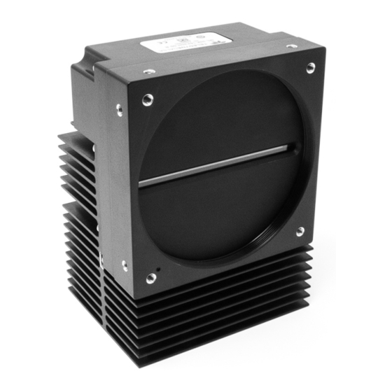
Mechanical Drawings Figure 7. Linea ML-FM-8K Camera Mechanical • Linea ML Multiline Monochrome / HDR CMOS Cameras... - Page 16 Figure 8. Linea ML-FM-16K Camera Mechanical • Linea ML Multiline Monochrome / HDR CMOS Cameras...
- Page 17 Figure 9. Linea ML-HM-16K Camera Mechanical • Linea ML Multiline Monochrome / HDR CMOS Cameras...
-
Page 18: Precautions
Install & Configure Frame Grabber & Software Because of the high bandwidth required by these cameras, we recommend a compatible Teledyne DALSA frame grabber (part numbers: OR-A8S0-FX840 (ML-FM) or OR-A8S0-PX870 (ML-HM)), or equivalent, described in detail on the teledynedalsa.com site here. -
Page 19: Using Sapera Camexpert
Using Sapera CamExpert CamExpert is the camera interfacing tool supported by the Sapera library. When used with the camera, CamExpert allows a user to access a camera’s features and parameters, and to test the operating modes. In addition, CamExpert can be used to save the camera’s user settings configurations to the camera or to save multiple configurations as individual camera parameter files on the host system (*.ccf). -
Page 20: Camexpert Panes
CamExpert Panes CamExpert, first instance: select Camera Link HS using the Device drop-down menu. Figure 10. CamExpert Frame Grabber Control Window The CamExpert application uses panes to organize the selection and configuration of camera files or acquisition parameters. Device Selector pane: View and select from any installed Sapera acquisition device. Once a device is selected, CamExpert will only show acquisition parameters for that device. - Page 21 Control Buttons: The display pane includes CamExpert control buttons. These are: Acquisition control button: Click once to start live grab, click again to stop. Single frame grab: Click to acquire one frame from device. Trigger button: With the I/O control parameters set to Trigger Enabled, click to send a single trigger command.
-
Page 22: Setting Up For Imaging
Setting Up for Imaging Figure 11. Camera I / O Connectors: 8K FM (left) & 16K HM (right) Camera I / O Connectors 1) Factory use only. 2) Data and control connectors: LC or CX4 AOC. 3) LED status indicators. 4) Power and GPIO connectors: +12 V to +24 V DC, Hirose 12-pin circular. -
Page 23: Power And Gpio Connections
When using a 12 V supply, voltage loss in the power cables will be greater due to the higher • current. Use the Camera Information category to refresh and read the camera’s input voltage measurement. Adjust the supply to ensure that it reads above or equal to 12 V. Note: If your power supply does not meet these requirements, then the camera performance specifications are not guaranteed. - Page 24 Voltage & Temperature Measurement for more details. Mating GPIO Cable Assembly Teledyne DALSA makes available for purchase an optional GPIO breakout cable (12-pin Female Hirose to 13-Pos Euro Block), as shown in the following drawing. Use accessory number #CR- GENC-IOP00 to order.
-
Page 25: Establishing Camera Communications
External Input Electrical Characteristics Switching Voltage Input Level Standard Low to high High to low Input Impedance 10K Ω 3.3V TTL 2.1V External Input Timing Reference Input Level Maximum Input Minimum Pulse Input Current Maximum Signal Propagation Delay @ Standard Frequency Width 3.3V TTL... -
Page 26: Selecting The Data Format
Selecting the Data Format The camera can output data in the following formats: Mono8 Mono12 Please refer to the frame grabber user’s documentation for further details on selection input and output pixel formats. Establishing Data Integrity 1. Use the camera’s internal triggering. This allows for initial imaging with a static object and no encoder input is required. -
Page 27: Camera Performance And Features
Camera Performance and Features This section is intended to be a progressive introduction to the features of the camera, including explanations of how to use them effectively. A detailed description of all features is found in Appendix A: GenICam Commands. Synchronizing to Object Motion Acquiring Images: Triggering the Camera Related Features: Exposure Mode, Trigger Mode, Trigger Source, Trigger Activation... -
Page 28: Measuring Line Rate (Trigger)
Measuring Line Rate (Trigger) See Camera Control Category in Appendix A for GenICam features associated with this section and how to use them. Related Feature: Measured Line Rate The Measured Line Rate command is used to read the line (trigger) rate being applied, externally or internally, to the camera. - Page 29 Direction Change Time The direction change time between forward and reverse is < 1 ms. Figure 12. Image with incorrect scan direction • Camera Performance and Features...
-
Page 30: Camera Orientation
Camera Orientation The diagram below shows the orientation of forward and reverse with respect to the camera body. Note that the diagram assumes the use of a lens on the camera, which inverts the image. Figure 13: Example of Object Movement and Camera Direction (8K camera shown) The diagram shows the designated camera direction. -
Page 31: Compensating For Encoder Errors (Spatial Correction)
Compensating for Encoder Errors (Spatial Correction) See Camera Control Category in Appendix A for GenICam features associated with this section and how to use them. Related Feature: Line Spatial Correction To achieve a sharp image in the vertical direction when running the camera in TDI mode or in HDR mode it is important that the lines being used are aligned correctly. - Page 32 Object Pixel Setup for 20 µm, Encoder set at 19 µm. Forward Scanning Can be corrected with 20 / 19 = 1.05 Line Spatial Correction Object Pixel Setup for 20 µm, Encoder set at 21 µm. Forward Scanning Can be corrected with 20 / 21 = 0.95 Line Spatial Correction If there are several different camera angles and associated illumination configurations in the inspection system, a single encoder pulse will not provide the correct timing for all the cameras.
-
Page 33: Parallax Correction: Using The Camera At Non-Perpendicular Angles To The Object
Parallax Correction: Using the Camera at Non-Perpendicular Angles to the Object See Camera Control Category in Appendix A for GenICam features associated with this section and how to use them. Related Features: Image Distortion Correction Mode, Image Distortion Correction Algorithm, Image Distortion Correction Line Selector, Image Distortion Parallax Correction Pixel Stretch When using a camera at an angle to the objects surface, the object pixel sizes for the three arrays are slightly different—this is due to parallax. - Page 34 Image example of artifact induced by parallax at the image extremity: Camera Angle, 8k Camera, 80 mm lens, 20 µm Object Pixel, Spatial Correction =9.2, No Parallax Correction • Camera Performance and Features...
-
Page 35: Establishing The Desired Response
Related Features: ExposureMode (Timed, Sequential) ExposureMode has 2 options: Timed and Sequential. Timed is the standard exposure operation as found in Teledyne DALSA line scan cameras. For operation of sequential mode, please see the section titled Exposure Mode Sequential. See the Exposure Control Section. -
Page 36: Exposure Time Selector
Use exposureTimeSelector to select whether to set the exposure time of each row independently or all to the same value. exposureDelay is only configurable when in Sequential exposure mode. Adjusting the exposure will result in a temporary loss of LVAL (8 lines) while the sensor is re-configured. Timed Exposure Mode Also called Global Reset Mode, the exposure begins when the line trigger occurs. -
Page 37: Sequential Mode Application Example
Sequential Mode Application Example The Linea ML is equipped with an innovative new mode that allows each line of the sensor to be exposed in a serial sequence with a single trigger applied to the camera. This can allow an object to be imaged with various lighting condition on a single pass of the image object past the camera. -
Page 38: Exposure Mode Sequential
Exposure Mode Sequential Relevant Features: ExposureMode, ExposureTime, ExposureDelay, TriggerDelay, OutputDelay, OutputDuration Unique to the Linea ML camera is the sequential exposure mode. For each trigger entering the camera the exposure for each line can be executed separately and in a serial sequence. This allows the user to set up different lighting conditions for each line. -
Page 39: Adjusting Responsivity
Figure 17Typical Sequential Timing The trigger signal entering the camera is routed to the sensor and also to each of the output control features. The TriggerDelay feature delays the trigger going to the sensor. This delay allows the user to turn on the LED before exposing the sensor. -
Page 40: Image Response Uniformity & Flat Field Calibration
It is desirable for camera performance to always use the maximum exposure time possible based on the maximum line rate of the inspection system and any margin that may be required to accommodate illumination degradation. However, it will be necessary to adjust the responsivity to achieve the desired output from the camera. -
Page 41: Saving & Rapidly Loading A Prnu Set Only
Settings and then select Miscellaneous > Current PRNU to download / upload a file. The file format is described in the document 03-084-20133 Linea ML Binary File Format, which can be obtained from Teledyne DALSA Technical Support. This document also includes Excel spread sheet examples. -
Page 42: Flat Field Calibration Regions Of Interest
One way to minimize this effect is to have the white target in motion during the calibration process. This has the result of averaging out any dirt or texture present. If this is not possible, the camera has a feature where a flat field calibration filter can be applied while generating the flat field correction coefficients—which can minimize the effects of dirt. -
Page 43: Hdr Demo Mode
If using 1 line only, there is the option of having high or low full well, using the sensorFullWellMode. There is a 4x difference in responsivity between these two modes and also a 4x difference in the full well. HDR Demo Mode In planar mode, the camera can be configured to output sensor row 0 and 1 separately. -
Page 44: Image Filters
Image Filters Related Features: imageFilterMode, imageFilterType, imageFilterKernalSize, imageFilterContrastRatio The camera has a selection of image filters that can be used to reduce image noise. Use the feature imageFilterMode to turn the filtering on or off. Use the feature imageFilterType to read the user information of the type of filter that is being used. -
Page 45: Binning
Binning See the section Image Format Control Category in Appendix A for GenICam features associated with this section and how to use them Related Features: Horizontal Binning, Vertical Binning In certain applications, lower image resolution may be acceptable if the desired defect detection can still be achieved. -
Page 46: Using Area Of Interest To Reduce Image Data & Enhance Performance
Using Area of Interest to Reduce Image Data & Enhance Performance See the section Image Format Control Category in Appendix A for GenICam features associated with this section and how to use them Related Features: AOI Count, AOI Selector, AOI Offset, AOI Width If the camera’s field of view includes areas that are not needed for inspection (also refer to the description in the Flat Field Calibration Region of Interest section) then the user may want to ignore this superfluous image data. -
Page 47: Customized Linearity Response (Lut)
Look Up Table to upload a file. The file format is described in 03-084-20133 Linea ML Binary File Format which can be obtained from Teledyne DALSA Technical Support. This document also includes Excel spread sheet examples. How to Generate LUT with CamExpert CamExpert can also be used to create a LUT file. -
Page 48: Adjusting Responsivity And Contrast Enhancement
10. This file can loaded into the camera using the File Access features. It is saved with the current Load / Save Configuration user set; ensure that a user set and not the factory set is selected, otherwise the upload will fail. 11. -
Page 49: Changing Output Configuration
Changing Output Configuration Pixel Format See the section Image Format Control Category in Appendix A for GenICam features associated with this section and how to use them Related Feature: Pixel Format The camera can output video data as 8-bit or 12-bit. The Mono8 Pixel Format are selected when the user wants to process image data as one, two, or three separate image planes. -
Page 50: Active Settings For Current Operation
A previously saved user setting (User Set 1 to 16) or the factory settings can be restored using the user set selector and user set load features. Either the factory setting or one of the user settings can be configured as the default setting, by selecting the set in the user set default selector. -
Page 51: User Setting
User Setting The user setting is the saved set of camera configurations that you can customize, resave, and restore. By default, the user settings are shipped with the same settings as the factory set. The command user set save saves the current settings to non-volatile memory as a user set. The camera automatically restores the user set configured as the default set when it powers up. -
Page 52: Appendix A: Genicam Commands
Features listed in the description table but tagged as Invisible are typically reserved for Teledyne DALSA Support or third party software usage, and not typically required by end user applications. The following feature tables describe these parameters along with their view attributes and in which version of the device the feature was introduced. -
Page 53: Camera Information Category
Camera Information Category Camera information can be retrieved via a controlling application. Parameters such as camera model, firmware version, etc. are read to uniquely identify the connected camera. These features are typically read-only. The Camera Information Category groups information specific to the individual camera. In this category the number of features shown is identical whether the view is Beginner, Expert or Guru. - Page 54 Display Name Feature Description Device Version & View Serial Number DeviceSerialNumber Displays the device’s factory set camera serial 1.00 number. Same as the camera label. (RO) Beginner Device User ID DeviceUserID Feature to store user-programmable identifier 1.00 of up to 31 characters. The default factory Beginner setting is the camera serial number.
-
Page 55: Built-In Self-Test Codes (Bist)
Built-In Self-Test Codes (BIST) In the Camera Information screen shot example above, the Power-On Status is showing the 23 status flags where ‘1’ is signaling an issue. When there are no issues, the Power-On status will indicated “Good”. Details of the BIST codes can be found in the Trouble Shooting Guide in Appendix B. Camera Power-Up Configuration Selection Dialog CamExpert provides a dialog box which combines the menu option used to select the camera’s power-up state and the options for the user to save or load a camera state as a specific user set... -
Page 56: Camera Control Category
Camera Control Category The camera control category, as shown by CamExpert, groups control parameters such as line rate, exposure time, scan direction and gain. Figure 24: Camera Control Panel • Camera Performance and Features... -
Page 57: Camera Control Feature Descriptions
Camera Control Feature Descriptions Display Name Feature Description Device Version & View Device Scan Type DeviceScanType Used to set the camera scanning mode. 1.00 Only standard line scan mode is available. Beginner Linescan (RO) SNFC Sensor Color Type sensorColorType Identifies the sensor color type 1.00 “Monochrome.”... - Page 58 Display Name Feature Description Device Version & View Exposure Time exposureTimeSelector Select which sensor line the exposure time 1.00 Selector applies to Beginner Exposure Delay exposureDelay In Sequential exposure mode this feature 1.00 defines the delay before each line is Beginner exposed.
- Page 59 Display Name Feature Description Device Version & View Image Distortion imageDistortionCorrectionMode Used to enable parallax correction 1.00 Correction Mode Expert Active Image Distortion imageDistortionCorrection Algorithm Read only. Indicates the type of correction 1.00 Correction Algorithm algorithm used i.e. Parallax Expert ParallaxCorrection Image Distortion imageDistortionCorrectionLineSelector...
-
Page 60: Digital I / O Control Category
Digital I / O Control Category The Digital I / O Control features are used to configure the camera’s GPIO pins. Figure 25 Digital I/O Control Panel • Camera Performance and Features... - Page 61 Digital I/O Control Feature Descriptions Display Name Feature Description Device Version & View Trigger Mode TriggerMode Determines the source of trigger to the camera, 1.00 internal or external DFNC Beginner Internal External Trigger Source TriggerSource Determines the source of external trigger 1.00 DFNC Beginner...
- Page 62 Rotary Encoder Multiplier rotaryEncoderMultiplier Specifies a multiplication factor for the rotary 1.00 encoder output pulse generator. DFNC Beginner Rotary Encoder Divisor rotaryEncoderDivider Specifies a division factor for the rotary encoder 1.00 output pulse generator. DFNC Beginner Rotary Encoder Rescaler rotaryEncoderRescalerOrder Specifies the order that the multiplier and divider are 1.00 Order...
-
Page 63: Flat Field Category
Refresh Line Status refreshLineStatus Command CamExpert to update LineStatus 1.00 DFNC Expert Line Status LineStatus Returns the current status of the line selected with 1.00 LineSelector DFNC Expert (RO) High High Flat Field Category The Flat Field controls, as shown by CamExpert, group parameters used to control the FPN and PRNU calibration process. - Page 64 Flat Field Control Feature Description Display Name Feature Description Device Version & View Flat Field Correction Mode flatfieldCorrectionMode 1.00 FPN and PRNU correction Beginner disabled. FPN and PRNU correction DFNC enabled. Clear Coefficents flatfieldCalibrationClearCoefficient Reset all FPN to 0 and all PRNU coefficients to 1.
- Page 65 Display Name Feature Description Device Version & View Calibrate PRNU flatfieldCalibrationPRNU Initiates the PRNU calibration 1.00 process Beginner DFNC Flat Field Correction Current flatfieldCorrectionCurrentActiveSet Selects the User PRNU set to be 1.00 Active Set saved or loaded. Guru DFNC Factory set can only be loaded. Factory Set Only the PRNU values are saved User set (1 thru 16)
-
Page 66: Image Format Control Category
Image Format Control Category The camera’s Image Format controls, as shown by CamExpert, group parameters used to configure camera pixel format, image cropping, binning and test pattern generation features. Figure 27: Image Format Panel Image Format Control Feature Description Display Name Feature Description Device... - Page 67 Output Width Width Horizontal width of the out pixels. Equals the 1.00 sum of AOI’s. Beginner DFNC Read only Height Height Height of the image provided by the device (in 1.00 object pixels) [1-4] Beginner DFNC Read only. Binning Vertical BinningVertical Number of vertically adjacent pixels to sum 1.00...
-
Page 68: Transport Layer Control Category
Transport Layer Control Category Note: All features shown in Guru visibility. Figure 28: Transport Layer Panel • Camera Performance and Features... - Page 69 Transport Layer Feature Descriptions Display Name Feature Description Device Version & View XML Major Version DeviceManifestXMLMajorVersion Together with 1.00 DeviceManifestXMLMinorVersion Beginner DFNC specifies the GenICam™ feature description file version (RO) XML Minor Version DeviceManifestXMLMinorVersion Together with 1.00 DeviceManifestXMLMajorVersion Beginner DFNC specifies the GenICam™...
-
Page 70: Acquisition And Transfer Control Category
Acquisition and Transfer Control Category Figure 29: Acquisition & Transfer Control Panel Acquisition and Transfer Control Feature Descriptions Display Name Feature Description Device Version & View Acquisition Mode AcquisitionMode The device acquisition mode defines the number of frames to 1.00 capture during an acquisition and the way it stops Beginner DFNC... -
Page 71: File Access Control Category
File Access Control Category The File Access control in CamExpert allows the user to quickly upload and download various data files to/from the connected the camera. The supported data files for the camera include firmware updates and Flat Field coefficients. Note that the communication performance when reading and writing large files can be improved by stopping image acquisition during the transfer. - Page 72 Display Name Feature Description View Current PRNU Accesses the PRNU coefficients that are currently being used by the camera (not necessarily saved). CameraData Download camera information and send for customer support. File Operation FileOperationSelector Selects the operation for the selected file in the device. This 1.00 Selector operation is executed when the File Operation Execute feature is...
-
Page 73: File Access Via The Camexpert Tool
File Access via the CamExpert Tool 1. Click on the “Setting…” button to show the file Access Control dialog box. Figure 31: File Access Control Tool 2. From the Type drop menu, select the file type that will be uploaded to the camera or downloaded from the camera. - Page 74 3. Set the FileOperationSelector to Open 4. Open the file by setting FileOperationExecute to 1. This is a read-write feature - poll it every 100 ms until it returns 0 to indicate it has completed 5. Read FileOperationStatus to confirm that the file opened correctly A return value of 0 is success.
-
Page 75: Download A List Of Camera Parameters
The camera data file includes the operational configuration and status of the camera. This text file can be downloaded from the camera and forwarded to Teledyne DALSA Technical Customer support team to aid in diagnosis of any reported issues. See Saving & Restoring Camera Setup Configurations of the user manual for details on downloading the Camera Data file. - Page 76 Built-In Self-Test Codes The Built-In Self-test (BIST) codes are located in the Camera Information pane under Power-on Status. None of these should occur in a properly functioning camera except OVER_TEMPERATURE. OVER_TEMPERATURE occurs if there ambient temperature is too high, there is insufficient air circulation or heat sinking.
-
Page 77: Resolving Camera Issues
Resolving Camera Issues Communications: No Camera Features when Starting CamExpert If the camera’s CamExpert GUI is opened and no features are listed, then the camera may be experiencing lane lock issues. While using the frame grabber CamExpert GUI you should be able to see a row of status indicators below the image area that indicates the status of the CLHS communications. - Page 78 for imperfections such as dust, scratches, paper grain, etc. in the white reference. Once the white reference is removed and the camera images the material to be inspected, any white reference imperfections will appear as vertical stripes in the image. If the white reference had imperfections that caused dark features, there will be a bright vertical line during normal imaging.
- Page 79 It is also important that the direction of image travel across the sensor is matched to the camera’s scan direction, as set by the user. See ‘Scan Direction’ in the user manual for more information. If the scan direction is incorrect, then the image will have a significant smear and image artifacts in the scan direction.
-
Page 80: Power Supply Issues
Power Supply Issues For safe and reliable operation, the camera input supply must be +12 V to +24 V DC. The power supply to the camera should be suitably current limited, as per the applied input voltage of between +12 V to +24 V. Assume a worst case power consumption of +24 W and a 150% current rating for the breaker or fuse. - Page 81 If the camera’s internal temperature exceeds +80 °C, then the camera will partially shut down to protect itself against damage. Commands can still be sent to the camera to read the temperature, but the image sensor will not be operational and LVAL in response to line triggers will not be generated. Additionally, the camera’s power will reduce to approximately 70% of normal operation.
- Page 82 Declaration of Conformity • Camera Performance and Features...
- Page 83 Document Revision History Revision Description Date Initial release. 26 February 2019 Note added that 300 kHz line rate achievable using AOI feature 13 June 2019 • in 8k cameras. Power / GPIO connector pin 8 revised to line 6 out. •...
Need help?
Do you have a question about the Linea ML ML-FM-16K15A and is the answer not in the manual?
Questions and answers