
Subscribe to Our Youtube Channel
Related Manuals for Dalsa Linea ML ML-FM-08K30H-00-R


Summary of Contents for Dalsa Linea ML ML-FM-08K30H-00-R
- Page 1 Linea ML Multiline Cameras Monochrome / HDR CMOS ML-FM-08K30H and ML-HM-16K30H sensors | cameras | frame grabbers | processors | software | vision solutions 03-032-20263-00 w ww.teledynedalsa.com...
- Page 2 All information provided in this manual is believed to be accurate and reliable. No responsibility is assumed by Teledyne DALSA for its use. Teledyne DALSA reserves the right to make changes to this information without notice. Reproduction of this manual in whole or in part, by any means, is prohibited without prior permission having been obtained from Teledyne DALSA.
-
Page 3: Table Of Contents
Contents LINEA ML MULTILINE MONOCHROME / HDR CMOS CAMERAS ESC RIPTIO N AMER A IGHLIGHTS Key Features Programmability Applications UMBER S AND OFTW AR E EQUIR EMENTS ER FORMANC E PECIFIC ATIO NS Flash Memory Size Certification & Compliance AMER A IXEL RR ANGEMENT AMER A... - Page 4 Sequential Mode Application Example Exposure Mode Sequential Adjusting Responsivity Image Response Uniformity & Flat Field Calibration Saving & Rapidly Loading a PRNU Set Only Setting Custom Flat Field Coefficients Flat Field Calibration Filter Flat Field Calibration Regions of Interest TDI S TAGE ELECTIO NS AND HDR Demo Mode...
- Page 5 Causes for Overheating & Power Shut Down EC LAR ATIO N O F O NFOR MITY OC UMENT EVISIO N ISTORY Linea ML Multiline Monochrome / HDR CMOS Cameras...
-
Page 6: Linea Ml Multiline Monochrome / Hdr Cmos Cameras
(LC or CX4, resolution dependent). Teledyne DALSA’s Linea ML cameras and compatible frame grabbers combine to offer a complete solution for the next generation of automatic optical inspection (AOI) systems. -
Page 7: Camera Highlights
Camera Highlights Key Features Highly responsive multiline CMOS 8K or 16K pixel resolution Up to 300 kHz aggregated line rates Very low noise Bi-directionality with fixed optical center Binning Robust Camera Link HS interface ... -
Page 8: Part Numbers And Software Requirements
Camera Link HS 150 kHz x 2 HDR mode Table 2: Frame Grabber Com patible Fram e grabber ML-FM-08K30H ML-HM-16K30H Teledyne DALSA OR-A8S0-FX840 OR-A8S0-PX870 Other compatible frame grabbers may be available from third-party vendors. Table 3: Software Softw are Product Num ber / Version Num ber... - Page 9 Mass < 500 g 1.2 kg Operating Temp +0 °C to +65°C, front plate temperature Optical Interface ML-FM-08K30H ML-HM-16K30H Lens Mount M58 x 0.75 mm M90 x 1 mm Sensor to Camera Front Distance 12 mm Sensor Alignment (aligned to sides of camera) Flatness 50 µm...
-
Page 10: Flash Memory Size
Flash Memory Size Table 5: Camera Flash Memory Size Cam era Flash m em ory size All models 4 GByte Certification & Compliance Table 6: Camera Certifications and Compliance Com pliance See, Declaration of Conformity. KC Registration Verified equipment registered under the Clause 3, Article 58-2 of Radio Waves Act. ML-HM-16K30H registration no. R-R- Td2-ML-HM-16K30H. -
Page 11: Supported Industry Standards
Supported Industry Standards GenICam™ The camera is GenICam compliant and implements a superset of the GenICam Standard Features Naming Convention specification V1.5. This description takes the form of an XML device description file using the syntax defined by the GenApi module of the GenICam specification. The camera uses the GenICam Generic Control Protocol (GenCP V1.0) to communicate over the Camera Link HS command lane. -
Page 12: Data Cables
The distance through which the data can be transmitted depends on the type of fiber optic used. Fiber optic cables are divided into four types: OM1, OM2, OM3, and OM4. The OM4 is used for distances > 300 m, but also requires SFP+ transceiver module changes. Contact Teledyne DALSA Support for more information. -
Page 13: Responsivity & Qe Plots
Responsivity & QE Plots Figure 3. Camera Spectral Responsivity Figure 4. Camera Quantum Efficiency Note: values measured using 8-bit, 1x gain, single row. Linea ML Multiline Monochrome / HDR CMOS Cameras... -
Page 14: Mechanical Drawings
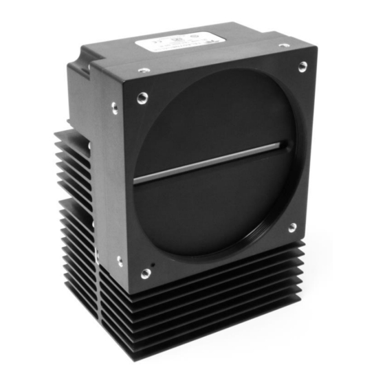
Mechanical Drawings Figure 5. Linea ML-FM-8K Camera Mechanical Linea ML Multiline Monochrome / HDR CMOS Cameras... - Page 15 Figure 6. Linea ML-HM-16K Camera Mechanical Linea ML Multiline Monochrome / HDR CMOS Cameras...
-
Page 16: Precautions
Install & Configure Frame Grabber & Software Because of the high bandwidth required by these cameras, we recommend a compatible Teledyne DALSA frame grabber (part numbers: OR-A8S0-FX840 (8K) or OR-A8S0-PX870 (16k)), or equivalent, described in detail on the teledynedalsa.com site, here. - Page 17 configurations to the camera or to save multiple configurations as individual camera parameter files on the host system (*.ccf). CamExpert can also be used to upgrade the camera’s software. An important component of CamExpert is its live acquisition display window. This window allows the user to verify the timing or control parameters in real-time, without needing to run a separate acquisition program.
-
Page 18: Camexpert Panes
CamExpert Panes CamExpert, first instance: select Camera Link HS using the Device drop-down menu. Figure 7. CamExpert Frame Grabber Control Window The CamExpert application uses panes to organize the selection and configuration of camera files or acquisition parameters. Device Selector pane: View and select from any installed Sapera acquisition device. Once a device is selected, CamExpert will only show acquisition parameters for that device. - Page 19 Trigger button: With the I/O control parameters set to Trigger Enabled, click to send a single trigger command. CamExpert display controls: (these do not modify the frame buffer data) Stretch image to fit, set image display to original size, or zoom the image to virtually any size and ratio.
-
Page 20: Setting Up For Imaging
Setting Up for Imaging Figure 8. Camera I / O Connectors: 8K (left) & 16K (right) Camera I / O Connectors 1) Factory use only. 2) Data and control connectors: LC (8K) and CX4 AOC (16K). 3) LED status indicators. 4) Power and GPIO connectors: +12 V to +24 V DC ±... -
Page 21: Power And Gpio Connections
When using a 12 V supply, voltage loss in t he power cables will be greater due to the higher current. Use the Camera Information category to refresh and read the camera’s input voltage measurement. Adjust the supply to ensure that it reads above or equal to 12 V. Note: If your power supply does not meet these requirements, then the camera performance specifications are not guaranteed. - Page 22 CamExpert. Refer to the section on Voltage & Temperature Measurement for more details. Mating GPIO Cable Assembly Teledyne DALSA makes available for purchase an optional GPIO breakout cable (12-pin Female Hirose to 13-Pos Euro Block), as shown in the following drawing. Use accessory number #CR- GENC-IOP00 to order.
-
Page 23: Establishing Camera Communications
Output Level Standard 3.3V TTL <0.4V @ 10mA* >3.1V @ 10mA* *See Linear Technology data sheet LTC2854 External Input Timing Reference Output Level Maxim um Output Minim um Pulse Output Maxim um Signal Propagation Delay @ Standard Frequency Width Current 3.3V TTL Line rate dependent 25 ns... - Page 24 3. Use a frame grabber CamExpert instance to capture, display, and analyze the test pattern image to verify the integrity of the connection. If the test pattern is not correct, check the cable connections and the frame grabber setup. 4. Disable the test pattern output. ...
-
Page 25: Camera Performance And Features
Camera Performance and Features This section is intended to be a progressive introduction to the features of the camera, including explanations of how to use them effectively. A detailed description of all features is found in Appendix A: GenICam Commands. Synchronizing to Object Motion Acquiring Images: Triggering the Camera Related Features: Exposure Mode, Trigger Mode, Trigger Source, Trigger Activation... -
Page 26: Maximum Line Rate
Related Feature: Measured Line Rate The Measured Line Rate command is used to read the line (trigger) rate being applied, externally or internally, to the camera. Maximum Line Rate The maximum line rate that the camera can achieve is determined by the number of CLHS lanes used and by the number of cables installed, as shown in the following table: Maxim um Line Rate (1 sensor line output, 8 bit) Cam era Model... - Page 27 Figure 9. Image with incorrect scan direction Camera Performance and Features...
-
Page 28: Camera Orientation
Camera Orientation The diagram below shows the orientation of forward and reverse with respect to the camera body. Note that the diagram assumes the use of a lens on the camera, which inverts the image. Figure 10: Example of Object Movement and Camera Direction (8K camera shown) The diagram shows the designated camera direction. -
Page 29: Compensating For Encoder Errors (Spatial Correction)
Compensating for Encoder Errors (Spatial Correction) See Camera Control Category in Appendix A for GenICam features associated with this section and how to use them. Related Feature: Line Spatial Correction To achieve a sharp image in the vertical direction when running the camera in TDI mode or in HDR mode it is important that the lines being used are aligned correctly. - Page 30 Object Pixel Setup for 20 µm, Encoder set at 19 µm. Forward Scanning Can be corrected with 20 / 19 = 1.05 Line Spatial Correction Object Pixel Setup for 20 µm, Encoder set at 21 µm. Forward Scanning Can be corrected with 20 / 21 = 0.95 Line Spatial Correction If there are several different c amera angles and associated illumination configurations in the inspection system, a single encoder pulse will not provide the correct timing for all the cameras.
-
Page 31: Parallax Correction: Using The Camera At Non-Perpendicular Angles To The Object
Parallax Correction: Using the Camera at Non-Perpendicular Angles to the Object See Camera Control Category in Appendix A for GenICam features associated with this section and how to use them. Related Features: Image Distortion Correction Mode, Image Distortion Correction Algorithm, Image Distortion Correction Line Selector, Image Distortion Parallax Correction Pixel Stretch When using a camera at an angle to the objects surface, the object pixel size s for the three arrays are slightly different—this is due to parallax. -
Page 32: Establishing The Desired Response
Image example of artifact induced by parallax at the image extremity : Camera Angle, 8k Camera, 80 mm lens, 20 µm Object Pixel, Spatial Correction =9.2, No Parallax Correction Establishing the Desired Response One of the important performance characteristics of the camera that will determine its suitability for an application is its responsivity and the associated noise level at the system’s maximum line rate and under the desired illumination conditions and lens configuration. -
Page 33: Exposure Mode
Related Features: ExposureMode (Timed, Sequential) ExposureMode has 2 options: Timed and Sequential. Timed is the standard exposure operation as found in Teledyne DALSA line scan cameras. For operation of sequential mode, please see the section titled Exposure Mode Sequential. See the Exposure Control Section. -
Page 34: Exposure Time Selector
Timed Exposure Mode Also called Global Reset Mode, the exposure begins when the line trigger occurs. If some rows have shorter exposure times then they are held in reset longer such that all the rows finish exposing at the same time and read out begins. The minimum exposure time depends on the number of rows being read out. - Page 35 Linea ML Bright Field Illumination Dark Field Illumination Object to Image Back Field Illumination Figure 13. Typical Lighting Configuration Camera Performance and Features...
-
Page 36: Exposure Mode Sequential
Exposure Mode Sequential Relevant Features: ExposureMode, ExposureTime, ExposureDelay, TriggerDelay, OutputDelay, OutputDuration Unique to the Linea ML camera is the sequential exposure mode. For each trigger entering the camera the exposure for each line can be executed separately and in a serial sequence. This allows the user to set up different lighting conditions for each line. -
Page 37: Adjusting Responsivity
Internal Timing Generation CLHS Framegrabber Exsync Trigger Delay Linea ML Sensor Trigger Activation Debouncer Input Line 1 GPIO Connector Rotary Encoder Multiply-Divide Input Line 2 Trigger Activation Debouncer Output Line 3 Output Line Invert Output Duration Output Delay Output Line 4 Output Line Invert Output Duration Output Delay... -
Page 38: Image Response Uniformity & Flat Field Calibration
Image Response Uniformity & Flat Field Calibration See the section Flat Field Category in Appendix A for GenICam features associated with this section and how to use them Related Features: Calibrate FPN, Calibrate PRNU, Calibration Algorithm, Calibration Target It is common to find that an image has a lower response at the edges of the camera’s field of view compared to its center. -
Page 39: Saving & Rapidly Loading A Prnu Set Only
Settings and then select Miscellaneous > Current PRNU to download / upload a file. The file format is described in the document 03-084-20133 Linea ML Binary File Format, which can be obtained from Teledyne DALSA Technical Support. This document also includes Excel spread sheet examples. -
Page 40: Flat Field Calibration Regions Of Interest
Flat Field Calibration Regions of Interest See the section Flat Field Category in Appendix A for GenICam features associated with this section and how to use them Related Features: ROI Offset X, ROI Width There are oc casions when the camera’s field of view includes areas that are beyond the material to be inspected. -
Page 41: Hdr Demo Mode
HDR Demo Mode In planar mode the camera can be configured to output sensor rows 0 and 1. Row 1 is 4x more responsive than row 0. The user could combine these with their own algorithm to create a High Dynamic Range (HDR) image. -
Page 42: Image Filter Contrast Ratio
Image Filter Contrast Ratio The image filter contrast ratio feature is used to determine when the filter is applied to the image data. The control looks at the ratio between two adjacent pixels (prior to filter processing) on the sides of the relevant pixel and determines the difference or contrast between those pixels. If the contrast ratio is greater than the value set by the user, then the filter automatically turns off for those two pixels. -
Page 43: Using Area Of Interest To Reduce Image Data & Enhance Performance
Note: The Binning parameters can only be changed when image transfer to the frame grabber is stopped. Refer to the “Acquisition and Transfer Control’ category in the appendix for details on stopping and starting the acquisition. Using Area of Interest to Reduce Image Data & Enhance Performance See the section Image Format Control Category in Appendix A for GenICam features associated with this section and how to use them Related Features: AOI Count, AOI Selector, AOI Offset, AOI Width... -
Page 44: Customized Linearity Response (Lut)
Look Up Table to upload a file. The file format is described in 03-084-20133 Linea ML Binary File Format which can be obtained from Teledyne DALSA Technical Support. This document also includes Excel spread sheet examples. How to Generate LUT with CamExpert CamExpert can also be used to create a LUT file. -
Page 45: Adjusting Responsivity And Contrast Enhancement
10. This file can loaded into the camera using the File Access features. It is saved with the current Load / Save Configuration user set; ensure that a user set and not the factory set is selected, otherwise the upload will fail. 11. -
Page 46: Using Two Clhs Cables
The camera can output video data as 8-bit or 12-bit. The Mono8 Pixel Format are selected when the user wants to process image data as one, two, or three separate image planes. Note: the Pixel Format and associated features can only be changed when image transfer to the frame grabber is stopped. -
Page 47: Active Settings For Current Operation
GenIcam Input By GenIcam Command By GenIcam Command 1. Select a ‘Factory Set’ 1. Select a ‘User Set’ 2. Initiate a ‘User Set Load’ 2. Initiate a ‘User Set Load’ Power Up Power Up Facrory Setting Active Setting User Setting Or Reset Or Reset By GenIcam GenIcam Command... -
Page 48: Default Setting
Default Setting The default setting is the set loaded when the camera is powered up. Either the factory or one of the user settings can be used as the default setting by selecting the set to use in the user set default selector. -
Page 49: Appendix A: Genicam Commands
Features listed in the description table but tagged as Invisible are typically reserved for Teledyne DALSA Support or third party software usage, and not typically required by end user applications. The following feature tables describe these parameters along with their view attributes and in which version of the device the feature was introduced. -
Page 50: Camera Information Category
Camera Information Category Camera information can be retrieved via a controlling application. Parameters such as camera model, firmware version, etc. are read to uniquely identify the connected camera. These features are typically read-only. The Camera Information Category groups information specific to the individual camera. In this category the number of features shown is identical whether the view is Beginner, Expert, or Guru. - Page 51 Display Nam e Feature Description Device Version & View Displays the device’s factory set camera serial Serial Number DeviceSerialNumber 1.00 number. Same as the camera label. (RO) Beginner Device User ID DeviceUserID Feature to store user-programmable identifier 1.00 of up to 31 characters. The default factory Beginner setting is the camera serial number.
-
Page 52: Built-In Self-Test Codes (Bist)
Built-In Self-Test Codes (BIST) In the Camera Information screen shot example above, the Power-On Status is showing the 23 status flags where ‘1’ is signaling an issue. When there are no issues, the Power-On status will indicated “Good”. Details of the BIST codes can be found in the Trouble Shooting Guide in Appendix B. Camera Power-Up Configuration Selection Dialog CamExpert provides a dialog box which combines the menu option used to select the camera’s power-up state and the options for the user to save or load a camera state as a specific user set... -
Page 53: Camera Control Feature Descriptions
Figure 21: Camera Control Panel Camera Control Feature Descriptions Display Nam e Feature Description Device Version & View Device Scan Type DeviceScanType Used to set the camera scanning mode. 1.00 Only standard line scan mode is available. Beginner Linescan (RO) SNFC Sensor Color Type sensorColorType... - Page 54 Display Nam e Feature Description Device Version & View Acquisition Line Rate AcquisitionLineRate Specifies the camera internal line rate, in Hz 1.00 w hen Trigger mode set to internal. Beginner Measured Line Rate measuredLineRate Specifies the line rate provided to the 1.00 camera by either internal or external source Beginner...
- Page 55 Display Nam e Feature Description Device Version & View Direction Source sensorScanDirectionSource This feature specifies how the scan direction 1.00 is controlled. Beginner Direction set w ith the sensorScanDirection Internal Internal feature Direction controlled by Line 2 Forw ard: low , Reverse: high Line 2 GPIO2 Direction is determined from the shaft...
-
Page 56: Digital I / O Control Category
Display Nam e Feature Description Device Version & View Image Distortion imageDistortionCorrectionLineSelector Used to select w hich line w ill be stretched to 1.00 Correction Line correct the image Expert Selector Row 1 Row 3 Image Distortion imageDistortionParallax Correction The stretch value in pixels at the ends of line 1.00 Parallax Correction PixelStretch... - Page 57 Digital I/O Control Feature Descriptions Display Nam e Feature Description Device Version & View Trigger Mode TriggerMode Determines the source of trigger to the camera, 1.00 internal or external DFNC Beginner Internal External Trigger Source TriggerSource Determines the source of external trigger 1.00 DFNC Beginner...
- Page 58 Rotary Encoder Multiplier rotaryEncoderMultiplier Specifies a multiplication factor for the rotary 1.00 encoder output pulse generator. DFNC Beginner Rotary Encoder Divisor rotaryEncoderDivider Specifies a division factor for the rotary encoder 1.00 output pulse generator. DFNC Beginner rotaryEncoderRescalerOrder Rotary Encoder Rescaler Specifies the order that the multiplier and divider are 1.00 Order...
-
Page 59: Flat Field Category
Refresh Line Status refreshLineStatus Command CamExpert to update LineStatus 1.00 DFNC Expert Line Status LineStatus Returns the current status of the line selected w ith 1.00 LineSelector DFNC Expert (RO) High High Flat Field Category The Flat Field controls, as shown by CamExpert, group parameters used to contro l the FPN and PRNU calibration process. - Page 60 Display Nam e Feature Description Device Version & View DFNC Peak Calculation of PRNU coefficients to bring all pixels to the peak. Peak, Image Filtered A low pass filter is applied to the average line values before calculating the coefficients. Use this algorithm if the calibration target is not uniformly w hite or if it is not possible to defocus the...
-
Page 61: Image Format Control Category
Display Nam e Feature Description Device Version & View Save Calibration flatfieldCalibrationSave Saves the User PRNU set 1.00 specified by Guru flatfieldCorrectionCurrentActiveSet DFNC to the camera. Load Calibration flatfieldCalibrationLoad Loads the User PRNU set 1.00 specified by Guru flatfieldCorrectionCurrentActiveSet DFNC to the camera and makes it active. - Page 62 Figure 24: Image Format Panel Image Format Control Feature Description Display Nam e Feature Description Device Version & View Pixel Format PixelFormat Output image pixel coding format of the 1.00 sensor. Beginner SFNC Mono8 Mono8 Mono12 Mono12 Pixel Size PixelSize Number of bits per pixel (RO) Alw ays “None”...
-
Page 63: Transport Layer Control Category
Height Height Height of the image provided by the device (in 1.00 object pixels) [1-4] Beginner DFNC Read only. Binning Vertical BinningVertical Number of vertically adjacent pixels to sum 1.00 together. This increases the intensity of the Beginner pixels and reduces the vertical resolution of SFNC the image [1, 2, 4] Binning Horizontal... - Page 64 Figure 25: Transport Layer Panel Transport Layer Feature Descriptions Display Nam e Feature Description Device Version & View XML Major Version DeviceManifestXMLMajorVersion Together w ith 1.00 DeviceManifestXMLMinorVersion Beginner specifies the GenICam™ feature description DFNC file version (RO) XML Minor Version DeviceManifestXMLMinorVersion Together w ith 1.00...
-
Page 65: Acquisition And Transfer Control Category
Last GenCP Status genCPStatus If a feature read or w rite fails then Sapera 1.00 only Beginner returns that it fails – read this feature to get DFNC actual reason for the failure Returns the last error Reading this feature clears it CLHS Discovery clhsDiscovery Selects w hether the camera needs to be... - Page 66 Figure 26: Acquisition & Transfer Control Panel Acquisition and Transfer Control Feature Descriptions Display Nam e Feature Description Device Version & View Acquisition Mode AcquisitionMode The device acquisition mode defines the number of frames to 1.00 capture during an acquisition and the w ay it stops Beginner DFNC Only continuous mode is currently available...
-
Page 67: File Access Control Category
File Access Control Category The File Access control in CamExpert allows the user to quickly upload and download various data files to/from the connected the camera. The supported data files for the camera include firmware updates and Flat Field coefficients. Note that the communication performance when reading and writing large files can be improved b y stopping image acquisition during the transfer. - Page 68 Display Nam e Feature Description View Current PRNU Accesses the PRNU coefficients that are currently being used by the camera (not necessarily saved). CameraData Dow nload camera information and send for customer support. FileOperationSelector File Operation Selects the operation for the selected file in the device. This 1.00 Selector operation is executed w hen the File Operation Execute feature is...
-
Page 69: File Access Via The Camexpert Tool
File Access via the CamExpert Tool 1. Click on the “Setting…” button to show the file Access Control dialog box. Figure 28: File Access Control Tool 2. From the Type drop menu, select the file type that will be uploaded to the camera or downloaded from the camera. - Page 70 3. Set the FileOperationSelector to Open 4. Open the file by setting FileOperationExecute to 1. This is a read-write feature - poll it every 100 ms until it returns 0 to indicate it has completed 5. Read FileOperationStatus to confirm that the file opened correctly A return value of 0 is success.
-
Page 71: Download A List Of Camera Parameters
The camera data file includes the operational configuration and status of the camera. This text file can be downloaded from the camera and forwarded to Teledyne DALSA Technical Customer support team to aid in diagnosis of any reported issues. See Saving & Restoring Camera Setup Configurations of the user manual for details on downloading the Camera Data file. - Page 72 Built-In Self-Test Codes The Built-In Self-test (BIST) codes are located in the Camera Information pane under Power-on Status. None of these should occur in a properly functioning camera except OVER_TEMPERATURE. OVER_TEMPERATURE occurs if there ambient temperature is too high, there is insufficient air circulation or heat sinking.
-
Page 73: Resolving Camera Issues
Resolving Camera Issues Communications: No Camera Features when Starting CamExpert If the camera’s CamExpert GUI is opened and no features are listed, then the camera may be experiencing lane lock issues. While using the frame grabber CamExpert GUI you should be able to see a row of status indicators below the image area that indicates the status of the CLHS communications. - Page 74 for imperfections such as dust, scratches, paper grain, etc. in the white reference. Once the white reference is removed and the camera images the material to be inspected, any white reference imperfections will appear as vertical stripes in the image. If the white reference had imperfections that caused dark features, there will be a bright vertical line during normal imaging.
- Page 75 It is also important that the direction of image travel across the sensor is matched to the camera’s scan direction, as set by the user. See ‘Scan Direction’ in the user manual for more information. If the scan direction is incorrect, then the image will have a significant smear and image artifacts in the scan direction.
-
Page 76: Power Supply Issues
Power Supply Issues For safe and reliable operation, the camera input supply must be +12 V to +24 V DC with a ±5% tolerance. The power supply to the camera should be suitably current limited, as per the applied input voltage of between +12 V to +24 V. - Page 77 If the camera’s internal temperature exceeds +80 °C, then the camera will partially shut down to protect itself against damage. Commands can still be sent to the camera to read the temperature, but the image sensor will not be operational and LVAL in response to line triggers will not be generated. Additionally, the camera’s power will reduce to approximately 70% of normal operation.
- Page 78 Declaration of Conformity Camera Performance and Features...
- Page 79 Document Revision History Revision Description Date Initial release. 26 Fe bruary 2019 Camera Performance and Features...
Need help?
Do you have a question about the Linea ML ML-FM-08K30H-00-R and is the answer not in the manual?
Questions and answers