
Related Manuals for Dalsa Everywhereyoulook ML-FC-08K07N


Summary of Contents for Dalsa Everywhereyoulook ML-FC-08K07N
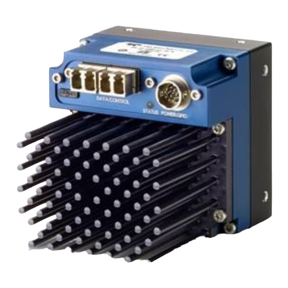
- Page 1 Linea ML Multispectral Cameras ML-FC-08K07N sensors | cameras | frame grabbers | processors | software | vision solutions 03-032-20271-01 www.teledynedalsa.com...
- Page 2 All information provided in this manual is believed to be accurate and reliable. No responsibility is assumed by Teledyne DALSA for its use. Teledyne DALSA reserves the right to make changes to this information without notice. Reproduction of this manual in whole or in part, by any means, is prohibited without prior permission having been obtained from Teledyne DALSA.
-
Page 3: Table Of Contents
Contents THE LINEA ML MULTISPECTRAL CAMERA ESCRIPTION AMERA IGHLIGHTS Key Features Programmability Applications UMBERS AND OFTWARE EQUIREMENTS ERFORMANCE PECIFICATIONS Flash Memory Size Certification & Compliance AMERA IXEL RRANGEMENT AMERA ROCESSING HAIN UPPORTED NDUSTRY TANDARDS GenICam™ Camera Link HS Data Cables &... - Page 4 Relevant GenICam features: ExposureMode, exposureTimeSelector, ExposureTime Exposure Time Selector Adjusting Responsivity Image Response Uniformity White Balancing Adjusting Flat Field Calibration Coefficients Saving & Loading a PRNU Set Only Setting Custom Flat Field Coefficients Flat Field Calibration Filter Flat Field Calibration Region of Interest MAGE ILTERS Kernels...
- Page 5 File Access via the CamExpert Tool CLHS File Transfer Protocol Upload File to Camera Download a List of Camera Parameters APPENDIX B: TROUBLE SHOOTING GUIDE IAGNOSTIC OOLS Camera Data File Voltage & Temperature Measurement Test Patterns – What can they indicate Built-In Self-Test Codes Status LED ESOLVING...
-
Page 6: The Linea Ml Multispectral Camera
(SFP+ or CX4, resolution dependent). Teledyne DALSA’s Linea ML color camera and compatible frame grabber combine to offer a complete solution for the next generation of automatic optical inspection (AOI) systems. -
Page 7: Camera Highlights
Camera Highlights Key Features • Highly responsive multiline CMOS • Quadlinear RGB + NIR outputs • 8K or 16K pixel resolution • Up to 300 kHz aggregated line rates • Very low noise • Bi-directionality with fixed optical center • Binning •... -
Page 8: Part Numbers And Software Requirements
8,192 pixels x 4 (RGB + NIR) 70 KHz (280 kHz, aggregate) 5.0 µm x 5.0 µm Table 3: Frame Grabber Compatible Frame grabber Product Number / Version Number Teledyne DALSA OR-A8S0-FX840 (8K camera) Table 4: Software Software Product Number / Version Number Camera firmware Embedded within camera GenICam™... - Page 9 Sensor to Camera 12 mm Front Distance Sensor Alignment (aligned to sides of camera) Flatness 50 µm y (parallelism) 100 µm ± 100 µm ± 100 µm ± 250 µm z ± 0.4° Operating Ranges Performance (All models) Notes Random Noise* <...
-
Page 10: Flash Memory Size
Flash Memory Size Table 6: Camera Flash Memory Size Camera Flash memory size All models 4 GByte Certification & Compliance Table 7: Camera Certification & Compliance Compliance EN 55011, FCC Part 15, CISPR 11, and ICES-003 Class A Radiated Emissions Requirements EN 55024 and EN 61326-1 Immunity to Disturbance RoHS per EU Directive 2011/65/EC and WEEE per EU Directive 2002/96/EC and China Electronic Industry Standard SJ/T11364-2006... -
Page 11: Camera Pixel Arrangement
Camera Pixel Arrangement 5 µm x 5 µm NIR Pixels 25 µm or 5 line spacing 5 µm x 5 µm Red Pixels 5um or 1 line spacing 15 µm or 3 line spacing 5um or 1 line spacing 5 µm x 5 µm Green Pixels 15 µm or 3 line spacing 5 µm x 5 µm Blue Pixels Figure 1 ML-FC-08K07N-00-R Color Pixel Structure... -
Page 12: Camera Processing Chain
Camera Processing Chain The diagram below details the sequence of arithmetic operations performed on the cameras sensor data, which the user can adjust to obtain an optimum image for their application. These adjustments are performed using camera features outlined in the ‘Review of Camera Performance and Features’... -
Page 13: Camera Link Hs
The distance through which the data can be transmitted depends on the type of fiber optic used. Recommended fiber optic cables are types OM3 and OM4. OM4 is used for distances > 300 m, but also requires SFP+ transceiver module changes. Contact Teledyne DALSA Support for more information. Table 8: LC Fiber Optic Cables Category... -
Page 14: Responsivity & Qe Plots
Camera Link HS cables can be bought from an OEM. OEM cables are also available for applications where flexing is present. Please refer to Teledyne DALSA’s website (www.teledynedalsa.com) for a list of recommended cable vendors and for part numbers. Each data cable is used for sending image data to and accepting command data from the frame grabber. - Page 15 Quantum Efficiency_ML-FC-08K07N (Savitzky Golay Filtering 5 pt) 50.00 45.00 40.00 35.00 30.00 25.00 20.00 15.00 10.00 5.00 0.00 1000 1100 Wavelength (nm) Red_Line3 QE Green_Line2 QE Blue_Line1 QE NIR_Line4 QE The Linea ML Multispectral Camera • 13...
-
Page 16: Mechanical Drawings
Mechanical Drawings ML-FC-08K07N-00-R 14 • The Linea ML Multispectral Camera... -
Page 17: Precautions
Precautions Read these precautions carefully before using the camera. Confirm that the camera’s packaging is undamaged before opening it. If the packaging is damaged please contact the related logistics personnel. Do not open the housing of the camera. The warranty is voided if the housing is opened. Keep the camera’s front plate temperature in a range of 0 °C to +65 °C during operation. -
Page 18: Install & Configure Frame Grabber & Software
Install & Configure Frame Grabber & Software Because of the high bandwidth required by this camera, we recommend a compatible Teledyne DALSA frame grabber (OR-A8S0-FX840, or equivalent), described in detail on the teledynedalsa.com site here. Follow the manufacturer’s installation instructions. -
Page 19: Camexpert Panes
CamExpert Panes CamExpert, first instance: select Camera Link HS RGB using the Device drop-down menu. Figure 4. CamExpert Frame Grabber Control Window The CamExpert application uses panes to organize the selecting and configuring of camera files or acquisition parameters. Device Selector pane: View and select from any installed Sapera acquisition device. Once a device is selected, CamExpert will only show acquisition parameters related to that device. - Page 20 Control Buttons: The Display pane includes CamExpert control buttons. These are: Acquisition control button: Click once to start live grab, click again to stop. Single frame grab: Click to acquire one frame from device. Trigger button: With the I/O control parameters set to Trigger Enabled, click to send a single trigger command.
-
Page 21: Setting Up For Imaging
Setting Up for Imaging Camera I / O Connectors 1) Factory use only. 2) Data and control connectors: LC 3) LED status indicators. 4) Power and GPIO connectors: +12 V to +24 V DC, Hirose 12-pin circular. Powering the Camera WARNING: When setting up the camera’s power supply follow these guidelines: •... -
Page 22: Power And Gpio Connections
• When using a +12 V supply, voltage loss in the power cables will be greater due to the higher current. Use the Camera Information category to refresh and read the camera’s input voltage measurement. Adjust the supply to ensure that it reads above or equal to +12 V. Note: If your power supply does not meet these requirements, then the camera performance specifications are not guaranteed. - Page 23 Voltage & Temperature Measurement for more details. Mating GPIO Cable Assembly Teledyne DALSA makes available for purchase an optional GPIO breakout cable (12-pin Female Hirose to 13-Pos Euro Block), as shown in the following drawing. Use accessory number #CR- GENC-IOP00 to order.
-
Page 24: External Input Electrical Characteristics
External Input Electrical Characteristics Table 10: External Input Electrical Characteristics Switching Voltage Input Level Standard Low to high High to low Input Impedance 10K Ω 3.3 V TTL 2.1 V External Input Timing Reference Table 11: External Timing Reference Input Level Maximum Input Minimum Pulse Input Current... -
Page 25: Establishing Camera Communications
Establishing Camera Communications Power up the camera and observe the LED which indicates the following status conditions: Table 14: LED States LED State Description Camera not power up or waiting for the software to start Constant Red The camera BIST status is not good. See BIST status for diagnosis. Blinking Red The camera has stopped output and has shut down some components due to an over temperature condition. -
Page 26: Review Of Camera Performance And Features
Review of Camera Performance and Features This section is intended to be a progressive introduction to the features of the camera, including explanations of how to use them effectively. A detailed description of all features is found in Appendix A: GenICam Commands. Synchronizing to Object Motion Triggering the camera Relevant Features: ExposureMode, TriggerMode, TriggerSource,... -
Page 27: Measuring Line Rate (Trigger)
Measuring Line Rate (Trigger) See Camera Control Category in Appendix A for GenICam features associated with this section and how to use them. Relevant Feature: measuredLineRate The camera has the means to measure the line (trigger) rate that is currently being applied to the trigger input of the camera, or what is being internally generated. - Page 28 Figure 6. Image with incorrect scan direction 26 • Review of Camera Performance and Features...
-
Page 29: Camera Orientation
Camera Orientation The diagram below shows the definition of forward and reverse with respect to a camera body. Note that the diagram assumes the use of a lens, which inverts the image. Figure 7: Example of Object Movement and Camera Direction with a Lens The mechanical diagram shows which direction is designated as forward for the camera. -
Page 30: Spatial Correction
Spatial Correction See Camera Control Category in Appendix A for GenICam features associated with this section and how to use them. Relevant Features: sensorLineSpatialCorrection The RGB+NIR camera has a quadlinear configuration—each set of color rows are spatially separated by three rows except for the NIR row which has 5 row spacing. 25um 15um 15um... - Page 31 1/256 of a row. The feature accepts up to two decimal places and will adjust the entered sub-pixel adjustment component accordingly. This feature can only be adjusted when the acquisition is stopped. Review of Camera Performance and Features • 29...
-
Page 32: Examples Of Color Artifacts Generated By A Small Encoder Error
Examples of color artifacts generated by a small encoder error: Figure 9: Color Artifacts Example (encoder 19 µm) Image Details: • Object Pixel Setup for 20 µm • Encoder set at 19 µm • Forward Scanning • Can be corrected with 20 / 19 = 1.05 Spatial Correction Figure 10: Color Artifacts Example (encoder 21µm) Image Details: •... -
Page 33: Parallax Correction: Using The Camera At Non-Perpendicular Angles To The Object
Parallax Correction: Using the Camera at Non-Perpendicular Angles to the Object See Camera Control Category in Appendix A for GenICam features associated with this section and how to use them. Relevant Features: imageDistortionCorrectionMode, imageDistortionCorrectionAlgorithm, imageDistortionCorrectionLineSelector, imageDistortionParallaxCorrectionPixelStretch When using a camera at an angle to the objects surface, the object pixel size for the red, green and blue pixel arrays are slightly different. - Page 34 Image example of color artifact induced by parallax at the image extremity Figure 12:Parallax Image Example Image Details: • Camera Angle • 8k Camera • 80 mm lens • 20 µm Object Pixel • Spatial Correction = 1.15 • No Parallax Correction 32 •...
-
Page 35: Establishing The Desired Response
Related Features: ExposureMode (Timed) ExposureMode: Timed. Timed is the standard exposure operation as found in Teledyne DALSA line scan cameras. See the Exposure Control Section. Line Rate Jitter If the exposure time is close to the line period there could be jitter in the line rate when it is synchronized to the sensor clock if ExposureMode = Timed. -
Page 36: Exposure Time Selector
Timed Exposure Mode Also called Global Reset Mode, the exposure begins when the line trigger occurs. If some rows have shorter exposure times, then they are held in reset longer such that all the rows finish exposing at the same time and read out begins. The minimum exposure time depends on the number of rows being read out. -
Page 37: Image Response Uniformity
Image Response Uniformity See the section Flat Field Category in Appendix A for GenICam features associated with this section and how to use them Relevant Features: flatfieldCalibrateFPN, flatfieldCalibrationPRNU, flatfieldCorrectionAlgorithm, flatfieldCalibrationTarget It is common to find an image with lower response at the edges of the camera’s field of view compared to its center. -
Page 38: White Balancing
White Balancing Relevant Features: BalanceWhiteAuto After performing PRNU calibration using the peak value as the target for each color, this may result in each color having a different level even though the target may be white. The difference is caused by the spectral content of the light source in combination with the spectral characteristics of the cameras color filters. -
Page 39: Adjusting Flat Field Calibration Coefficients
03-084-20133 Linea ML Binary File Format which can be obtained from Teledyne DALSA Technical Support. This document also includes Excel spread sheet examples. Once the PRNU coefficients are uploaded, they are used immediately by the camera. To avoid loss at power up or changing row settings, they should be saved in one of the 8 available user sets. -
Page 40: Flat Field Calibration Filter
Flat Field Calibration Filter See the section Flat Field Category in Appendix A for GenICam features associated with this section and how to use them Relevant Features: flatfieldCorrectionAlgorithm If a sheet of material is being used as a white target, it must be completely free of blemishes and texture. -
Page 41: Image Filters
Image Filters Relevant Features: imageFilterMode, imageFilterType, imageFilterKernelSize, imageFilterContrastRatio The camera has a selection of image filters that can be used to reduce image noise. Use the feature imageFilterMode to turn the filtering on or off. Use the feature imageFilterType to read the user information of the type of filter that is being used. -
Page 42: Binning
Binning See the section Image Format Control Category in Appendix A for GenICam features associated with this section and how to use them Relevant Features: BinningHorizontal, BinningVertical Binning is the process where the charge on two (or more) adjacent pixels is combined. This results in increased light sensitivity as there is twice the sensor area to capture photons. -
Page 43: Using Area Of Interest (Aois)
Using Area of Interest (AOIs) Reduce Image Data & Enhance Performance See the section Image Format Control Category in Appendix A for GenICam features associated with this section and how to use them. Relevant Features: multipleROICount, multipleROISelector, multipleROIOffsetX, multipleROIWidth If the camera’s field of view includes areas that are not needed for inspection (also refer to the description in the Flat Field Calibration Region of Interest), then the user may want to ignore this superfluous image data. -
Page 44: Customized Linearity Response (Lut)
Look Up Table to upload a file. The file format is described in 03-084-20133 Linea Binary File Format which can be obtained from Teledyne DALSA Technical Support. This document also includes Excel spread sheet examples. How to Generate LUT with CamExpert CamExpert can also be used to create a LUT file. -
Page 45: Important Points
Important points: • The frame grabber must be configured mono 12 bits in, 16 bits out. • In the Parameters explorer a frame grabber feature must be selected, not a camera feature. • The Lookup table must be enabled to be created. But should be disabled to use the camera LUT. -
Page 46: Adjusting Responsivity And Contrast Enhancement
Adjusting Responsivity and Contrast Enhancement See the section Camera Control Category in Appendix A for GenICam features associated with this section and how to use them. Related Features: GainSelector, Gain, BlackLevel It is best for camera performance to always use the maximum exposure time possible based on the maximum line rate of the inspection system and any margin that may be required to accommodate illumination degradation. -
Page 47: Changing Output Configuration
Changing Output Configuration Pixel Format See the section Image Format Control Category in Appendix A for GenICam features associated with this section and how to use them Relevant Features: PixelFormat, ComponentSelector, ComponentEnable, ComponentID Mono8Color Combinations (Color ID) Approximate Maximum Line Rate Enhancement Blue Only 2.8x Green Only... -
Page 48: Saving & Restoring Camera Setup Configurations
Saving & Restoring Camera Setup Configurations See the section Camera Information Category in Appendix A for GenICam features associated with this section and how to use them Relevant Features: UserSetSelector, UserSet1 thru UserSet16, UserSetDefaultSelector, UserSetLoad, UserSetSave An inspection system may require several different illumination, resolution, and responsivity configurations in order to cover the different types of inspection it is expected to perform. -
Page 49: Active Settings For Current Operation
Active Settings for Current Operation Active settings are those settings used while the camera is running. And include all unsaved changes made by GenICam input to the settings. These active settings are stored in the camera’s volatile memory and will be lost and cannot be restored if the camera resets, is powered down, or loses power during operation. -
Page 50: Appendix A: Genicam Commands
Features listed in the description table but tagged as Invisible are typically reserved for Teledyne DALSA Support or third party software usage, and not typically required by end user applications. The following feature tables describe these parameters along with their view attributes and in which version of the device the feature was introduced. -
Page 51: Camera Information Category
Camera Information Category Camera information can be retrieved via a controlling application. Parameters such as camera model, firmware version, etc. are read to uniquely identify the connected camera. These features are typically read-only. The Camera Information Category groups information specific to the individual camera. In this category the number of features shown is identical whether the view is Beginner, Expert, or Guru. -
Page 52: Built-In Self-Test Codes (Bist)
Display Name Feature Description View Power-on User Set UserSetDefaultSelector Selects the camera configuration set to load Beginner and make active on camera power-up or reset. Allows the user to select between the factory set and 1 to 16 user sets to be loaded at power up The camera configuration sets are stored in camera non-volatile memory. -
Page 53: Camera Power-Up Configuration Selection Dialog
Camera Power-Up Configuration Selection Dialog Figure 20 CamExpert Power-up Configuration Dialog CamExpert provides a dialog box which combines the menu option used to select the camera’s power-up state and the options for the user to save or load a camera state as a specific user set that is retained in the camera’s non-volatile memory. -
Page 54: Camera Control Category
Camera Control Category The camera control category, as shown by CamExpert, groups control parameters such as line rate, exposure time, scan direction, and gain. Figure 21: Camera Control Panel Camera Control Feature Descriptions Display Name Feature Description View Device Scan DeviceScanType Used to set the camera scanning mode. - Page 55 Display Name Feature Description View Exposure Time ExposureTime Sets the exposure time (in Beginner microseconds). Can set all or individual rows. Exposure Time exposureTimeSelector Selects which line the exposure time is Beginner Selector applied to. DFNC Exposure time applied to all channels. Exposure time applied to red channel.
- Page 56 Display Name Feature Description View Image Distortion imageDistortionCorrectionAlgorithm Read only. Indicates the type of Expert Correction correction algorithm used i.e Parallax DFNC Algorithm Image Distortion imageDistortionCorrectionLineSelector Selects whether the Blue (and green) line Expert Correction Line or the Red (and green) line is stretched. DFNC Selector Acquisition must be stopped to modify.
-
Page 57: Digital I/O Control Category
Digital I/O Control Category The camera’s Digital I/O Control category is used to configure the camera’s GPIO pins. Figure 22: Digital I/O Control Panel Digital I/O Control Feature Descriptions Display Name Feature Description View Trigger Mode TriggerMode Determines the source of trigger to the camera. Beginner Internal Internal... -
Page 58: Rotary Encoder Direction
Display Name Feature Description View rotaryEncoderDirection Specifies the phase which defines the encoder DFNC Rotary Encoder Direction forward direction. Beginner Counter Clockwise CounterClockwise Inspection goes forward when the rotary encoder direction is counter clockwise (phase A is ahead of phase B). Clockwise Clockwise Inspection goes forward when the rotary encoder... - Page 59 Display Name Feature Description View The line signal is inverted. Output Line Software outputLineSoftwareCmd Set the GPIO out value when outputLineSource is DFNC Command off. Expert DFNC Refresh Line Status refreshLineStatus Update the LineStatus feature Expert Line Status LineStatus Returns the current state of the GPIO line selected DFNC with the LineSelector feature.
-
Page 60: Flat Field Category
Flat Field Category The Flat Field controls, as shown by CamExpert, group parameters used to control the FPN and PRNU calibration process. Figure 23: Flat Field Panel Flat Field Control Feature Description Display Name Feature Description View Mode flatfieldCorrectionMode Beginner DFNC FPN and PRNU correction disabled. - Page 61 Display Name Feature Description View Set Target, Image Filtered TargetFiltered A low pass filter is applied to the average line values before calculating the coefficients. Use this algorithm if the calibration target is not uniformly white or if it is not possible to defocus the image.
- Page 62 Display Name Feature Description View Active Active Enable the image filter Image Filter Type imageFilterType Specifies the image filter type. Read- Beginner only. DFNC Weighted Average Weighted_Average Wieght average algorithm. Image Filter Kernel Size imageFilterKernelSize Selects the kernel size. Beginner DFNC Kernel 1x3 KERNEL_1x3...
-
Page 63: Image Format Control Category
Image Format Control Category The camera’s Image Format controls, as shown by CamExpert, group parameters used to configure camera pixel format, image cropping, binning and test pattern generation features. Figure 24: Image Format Panel Image Format Control Feature Description Display Name Feature Description Device... - Page 64 PRNU file using the FileAccess > Miscellaneous > User PRNU feature. The PRNU coefficient will be applied to a midscale (128 DN) test image. Contact Teledyne DALSA support for an Excel file that can help with this. AOI Count Horizoontal multipleROICount Specified the number of AOI’s in an...
- Page 65 AOI Width multipleROIWidth Width of the start of a single Area of Beginner Interest to be output. DFNC Minimum is 96 per lane. e.g., if there is only one AOI spread across the 5 lanes then the minimum is 5 x 96 = 480. Maximum of the sum of AOI width’s is the sensor width.
-
Page 66: Transport Layer Control Category
Transport Layer Control Category Note: All features shown in Guru visibility. Figure 25: Transport Layer Panel Transport Layer Feature Descriptions Display Name Feature Description Device Version & View XML Major Version DeviceManifestXMLMajorVersion Together with Beginner DeviceManifestXMLMinorVersion specifies the GenICam™ feature description XML file version (RO) XML Minor Version... -
Page 67: Acquisition And Transfer Control Category
Acquisition and Transfer Control Category The Acquisition and Transfer controls as shown by CamExpert, has parameters used to configure the acquisition modes of the device. Figure 26: Acquisition & Transfer Control Panel Acquisition and Transfer Control Feature Descriptions Display Name Feature Description Device Version... -
Page 68: File Access Control Category
File Access Control Category The File Access control in CamExpert allows the user to quickly upload and download various data files to/from the connected the camera. The supported data files for the camera include firmware updates and Flat Field coefficients. Note that the communication performance when reading and writing large files can be improved by stopping image acquisition during the transfer. - Page 69 Display Name Feature Description View File Access Buffer FileAccessBuffer Defines the intermediate access buffer that allows the exchange Guru of data between the device file storage and the application. File Access Offset FileAccessOffset Controls the mapping offset between the device file storage and Guru the file access buffer.
-
Page 70: File Access Via The Camexpert Tool
File Access via the CamExpert Tool 1. Click on the “Setting…” button to show the file Access Control dialog box. Figure 28: File Access Control Tool 2. From the Type drop menu, select the file type that will be uploaded to the camera or downloaded from the camera. -
Page 71: Clhs File Transfer Protocol
CLHS File Transfer Protocol If you are not using CamExpert to perform file transfers, pseudo-code for the CLHS File Transfer Protocol is as follows. Download File from Camera 1. Select the file by setting the FileSelector feature 2. Set the FileOpenMode to Write 3. -
Page 72: Upload File To Camera
3. In the “Type” drop down box select “Miscellaneous.” 4. In the “File selector” drop down box select “CameraData.” 5. Hit “Download” 6. Save the text file and send the file to Teledyne DALSA customer support. 70 • Appendix A: GenICam Commands... -
Page 73: Appendix B: Trouble Shooting Guide
The Camera Data file includes the operational configuration and status of the camera. This text file can be downloaded from the camera and forwarded to Teledyne DALSA Technical Customer support team to aid in diagnosis of any reported issues. See Saving & Restoring Camera Setup Configurations of the user manual for details on downloading the Camera Data file. -
Page 74: Built-In Self-Test Codes
Built-In Self-Test Codes The Built-In Self-test (BIST) codes are located in the Camera Information pane under Power-on Status. None of these should occur in a properly functioning camera except OVER_TEMPERATURE. OVER_TEMPERATURE occurs if there ambient temperature is too high, there is insufficient air circulation or heat sinking. -
Page 75: Resolving Camera Issues
Resolving Camera Issues Communications No Camera Features when Starting CamExpert If the camera’s CamExpert GUI is opened and no features are listed, then the camera may be experiencing lane lock issues. While using the frame grabber CamExpert GUI you should be able to see a row of status indicators below the image area that indicates the status of the CLHS communications. -
Page 76: Image Quality Issues
Image Quality Issues Vertical Lines Appear in Image after Calibration The purpose of flat field calibration is to compensate for the lens edge roll-off and imperfections in the illumination profiles by creating a uniform response. When performing a flat field calibration, the camera must be imaging a flat white target that is illuminated by the actual lighting used in the application. - Page 77 Continuously Smeared, Compressed or Stretched Images When accurate synchronization is not achieved, the image will appear smeared in the scan direction. If the EXSYNC pulses are coming too fast, then the image will appear smeared and stretched in the machine direction. If the pulses are too slow, then the image will appear smeared and compressed.
-
Page 78: Power Supply Issues
Power Supply Issues For reliable operation the camera input supply must be within +12 V to +24 V DC. The power supply to the camera should be suitably current limited as per the applied input voltage of between +12 V to +24 V. Assume a worst case power consumption of 24 W and a 150% current rating for the breaker or fuse. -
Page 79: Declarations Of Conformity
This equipment is intended to be a component of a larger industrial system. EU and UKCA Declaration of Conformity Teledyne DALSA declares that this product complies with applicable standards and regulations. Changes or modifications not expressly approved by the party responsible for compliance could void the user's authority to operate the equipment. -
Page 80: Document Revision History
Document Revision History Revision Description Date Preliminary Draft. Aug 1, 2020 Updated spectral and QE response graphs Feb 10, 2022 78 • Document Revision History... -
Page 81: Contact Information
Sales Information Visit our web site: http://www.teledynedalsa.com/en/products/imaging/ Email: mailto:info@teledynedalsa.com Canadian Sales Teledyne DALSA — Head office Teledyne DALSA — Montreal office 605 McMurray Road 880 Rue McCaffrey Waterloo, Ontario, Canada, N2V 2E9 Saint-Laurent, Quebec, Canada, H4T 2C7 Tel: 519 886 6000...
Need help?
Do you have a question about the Everywhereyoulook ML-FC-08K07N and is the answer not in the manual?
Questions and answers