Table of Contents
Advertisement
Quick Links
Advertisement
Table of Contents

Subscribe to Our Youtube Channel
Related Manuals for Supermicro X6DLP-EG2


Summary of Contents for Supermicro X6DLP-EG2
- Page 1 UPER X6DLP-4G2 X6DLP-EG2 USER’S MANUAL Revision 1.0c...
- Page 2 Please Note: For the most up-to-date version of this manual, please see our web site at www.supermicro.com. SUPER MICRO COMPUTER reserves the right to make changes to the product described in this manual at any time and without notice.
-
Page 3: Manual Organization
Enhanced Intel SpeedStep Technology (EIST), and is ideal for high performance, and low power communications infrastructure environments. Please refer to the motherboard specifi cations pages on our web site (http://www.supermicro.com/products/ motherboard/) for updates on supported processors. This product is intended to be professionally installed. -
Page 4: Table Of Contents
Checklist ... 1-1 Contacting Supermicro ... 1-2 X6DLP-4G2/X6DLP-EG2 Image ... 1-3 X6DLP-4G2/X6DLP-EG2 Layout ... 1-4 X6DLP-4G2/X6DLP-EG2 Quick Reference ... 1-5 Motherboard Features ... 1-6 Intel E7520 Chipset: System Block Diagram ... 1-8 Chipset Overview ... 1-9 Special Features ... 1-10 Recovery from AC Power Loss ... - Page 5 Reset Button ... 2-12 Power Button ... 2-12 2-5 Connecting Cables ... 2-13 ATX Power Connector ... 2-13 Processor Power Connector ... 2-13 Chassis Intrusion ... 2-14 Universal Serial Bus (USB0/1) ... 2-14 Wake-On-LAN ... 2-15 Wake-On-Ring ... 2-15 Serial Ports ... 2-16 GLAN (Ethernet Port) ...
- Page 6 X6DLP-4G2/X6DLP-EG2 User's Manual Chapter 3: Troubleshooting Troubleshooting Procedures ... 3-1 Before Power On ... 3-1 No Power ... 3-1 No Video ... 3-1 Losing the System’s Setup Confi guration ... 3-1 Memory Errors ... 3-2 Technical Support Procedures ... 3-2 Frequently Asked Questions ...
-
Page 7: Chapter 1: Introduction
Checklist Congratulations on purchasing your computer motherboard from an acknowledged leader in the industry. Supermicro boards are designed with the utmost attention to detail to provide you with the highest standards in quality and performance. Check that the following items have all been included with your motherboard. If anything listed here is damaged or missing, contact your retailer. -
Page 8: Contacting Supermicro
X6DLP-4G2/X6DLP-EG2 User's Manual Contacting Supermicro Headquarters Address: SuperMicro Computer, Inc. 980 Rock Ave. San Jose, CA 95131 U.S.A. Tel: +1 (408) 503-8000 Fax: +1 (408) 503-8008 Email: marketing@supermicro.com (General Information) support@supermicro.com (Technical Support) Web Site: www.supermicro.com Europe Address: SuperMicro Computer B.V. -
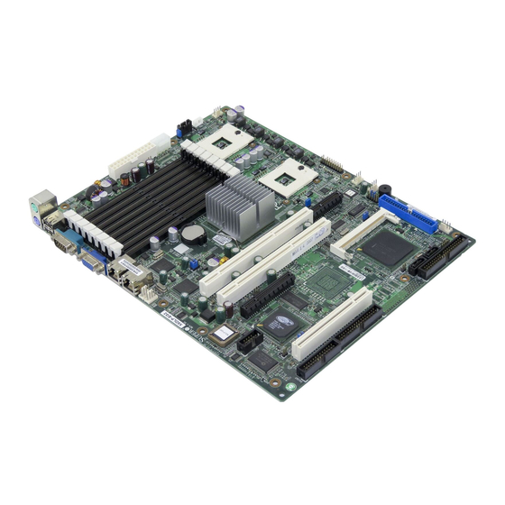
Page 9: X6Dlp-4G2/X6Dlp-Eg2 Image
Chapter 1: Introduction Figure 1-1. X6DLP-4G2/X6DLP-EG2 Image... - Page 10 X6DLP-4G2/X6DLP-EG2 User's Manual Figure 1-2. SUPER X6DLP-4G2/X6DLP-EG2 Motherboard Layout (not drawn to scale) JLAN1 Battery JLAN2 Important Notes to the User • All images and graphics shown in this manual were based upon the latest PCB Revision available at the time of publishing of this manual. The mother- board you've received may or may not look exactly the same as the graphics shown in this manual.
- Page 11 Quick Reference ( X6DLP-4G2/X6DLP-EG2) Jumper Description J13/J15 PCI #1/PCI-X #5,#6 to System SMB JBT1 CMOS Clear JPA1 (*Note) SCSI Controller Enable JPA2 (*Note) SCSI Channel Term. Enable Power Force on JPG1 VGA Enable JPL1/JPL2 LAN1/LAN 2 Enable/Disable JPR1 Power Fail Alarm Reset...
-
Page 12: Motherboard Features
X6DLP-4G2/X6DLP-EG2 User's Manual Motherboard Features Latest CPU technology! • Intel single or dual Sossaman Dual-Core Processors @ an 667MHz Front Side • Architecture with Dynamic Execution, Address/Data/Registry Parity on the FSB, Intel Thermal Management, Enhanced Intel SpeedStep (EIST) supported Memory •... - Page 13 Chapter 1: Introduction ACPI/ACPM Power Features • Slow blinking LED for suspend state indicator • Main switch override mechanism • Wake-on-Ring (WOR)/Wake-on-LAN (WOL) support • Power-on mode for AC power recovery LED Indicators • System/CPU Overheat LED • Suspend State LED •...
- Page 14 X6DLP-4G2/X6DLP-EG2 User's Manual PCI-EXPX8 PCI-EXPX8 SCSI CONN (INTERNAL) 82573 82573 AIC-7901 PCI-X(66MHZ) CHANNEL A 32-BIT 33MHZ VIDEO RAGE XL VIDEO SRAM Figure 1-9. Block Diagram of the E7520 Chipset Note: This is a general block diagram. Please see the previous Motherboard Features pages for details on the features of each motherboard.
-
Page 15: Chipset Overview
The E7520 Chipset Built upon the functionality and the capability of the 7520 chipset, the X6DLP-4G2/ X6DLP-EG2 motherboard provides the performance and feature set required for dual processor-based servers, with confi guration options optimized for communica- tions, presentation, storage, computation or database applications. The Intel E7520 chipset consists of the following components: the E7520 Memory Controller Hub (MCH) and the 6300ESB I/O Controller Hub (6300ESB ICH). -
Page 16: Special Features
The default setting is Last State. PC Health Monitoring This section describes the PC health monitoring features of the SUPER X6DLP- 4G2/X6DLP-EG2. All have an onboard System Hardware Monitor chip that supports PC health monitoring. Onboard Voltage Monitors for the CPU Cores, +1.8V, +3.3V, +5V, +12V, -12V, +3.3V Standby, and VBAT... -
Page 17: 1-5 Acpi Features
Thermal Management/CPU VRM Overheat When the CPU reaches 70 CPU Voltage will decrease to reduce CPU power consumption. When CPU tem- perature reaches 78 C (*Default) and above, the system will go into the throttling state. The Overheat LED and the Alarm Buzzer will be turned on. The CPU slows down as well. -
Page 18: Power Supply
It is even more important for processors that have high CPU clock rates. The SUPER X6DLP-4G2/X6DLP-EG2 can only accommodate ATX 24-pin power supplies. Although most power supplies generally meet the specifi cations required by the CPU, some are inadequate. You should use one that will supply at least 200W of power and includes the additional +12V, 8-pin power connector - an even higher wattage power supply is recommended for high-load confi... -
Page 19: Super I/O
Chapter 1: Introduction It is strongly recommended that you use a high quality power supply that meets ATX power supply Specifi cation 2.02 or above. It must also be SSI compliant (info. at http://www.ssiforum.org/). Additionally, in areas where noisy power transmission is present, you may choose to install a line fi... - Page 20 X6DLP-4G2/X6DLP-EG2 User's Manual Notes 1-14...
-
Page 21: Chapter 2: Installation
Static-Sensitive Devices Electric-Static-Discharge (ESD) can damage electronic com ponents. To prevent damage to your system board, it is important to handle it very carefully. The following measures are generally suffi cient to protect your equipment from ESD. Precautions • Use a grounded wrist strap designed to prevent static discharge. •... -
Page 22: 2-2 Processor And Heatsink Installation
X6DLP-4G2/X6DLP-EG2 User's Manual 2-2 Processor and Heatsink Installation When handling the processor package, avoid placing direct pressure on the label area of the fan. Also, do not place the motherboard on a conductive surface, which can damage the BIOS battery and prevent the system from booting up. - Page 23 Installing the CPU into the CPU socket 1. Locate Pin 1 on the socket and Pin 1 on the CPU as shown in the pictures. 2. The CPU socket should come in the unlocked position. To un- lock the CPU socket, using a fl at head driver, turn the CPU lock counter-clockwise until it cannot turn further.
- Page 24 X6DLP-4G2/X6DLP-EG2 User's Manual Heatsink Installation 1. Do not apply any thermal grease to the heatsink or the CPU die-the if the required amount has already been applied. 2. Locate the four heatsink mounting holes on the motherboard. 3. Place the heatsink on top of the CPU and insert heatsink's four pegs into the heatsink mounting holes.
- Page 25 Mounting the Motherboard in the Chassis All motherboards have standard mounting holes to fi t different types of chassis. Make sure that the locations of all the mounting holes for both motherboard and chassis match. Make sure that the metal standoffs click in or are screwed in tightly.
-
Page 26: 2-3 Installing Dimms
3. Gently press down on the DIMM module until it snaps into place in the slot. Repeat for all modules (see step 1 above). Memory Support The X6DLP-4G2/X6DLP-EG2 supports up to 16 GB of Reg. ECC DDRII 400 (PC3200) memory. Notes: 1. -
Page 27: Control Panel Connectors And Io Ports
Figure 2-2. Installing and Removing DIMMs To Install: Insert the module vertically and press down until it snaps into place. Pay attention to the alignment notch at the bottom. To Remove: Use your thumbs to gently push near the edge of both ends of the module. -
Page 28: Front Control Panel
These connectors are designed specifi - cally for use with Supermicro server chassis. See Figure 2-4 for the descriptions of the various control panel buttons and LED indicators. Refer to the following section for descriptions and pin defi... -
Page 29: Front Control Panel Pin Defi Nitions
C. Front Control Panel Pin Defi nitions NMI Button The non-maskable interrupt button header is located on pins 19 and 20 of JF1. Refer to the table on the right for pin defi nitions. Power LED The Power LED connection is located on pins 15 and 16 of JF1. -
Page 30: Hdd Led
X6DLP-4G2/X6DLP-EG2 User's Manual HDD LED The HDD LED connection is located on pins 13 and 14 of JF1. Attach the hard drive LED cable here to display disk activity (for any hard drives on the system, including SCSI, Serial ATA and IDE). -
Page 31: Overheat/Fan Fail Led
Overheat/Fan Fail LED Connect an LED to the OH/Fan Fail LED connection on pins 7 and 8 of JF1 to provide advanced warning of chassis overheating and fan failure. Refer to the table on the right for pin defi nitions. Power Fail LED The Power Fail LED connection is located on pins 5 and 6 of JF1. -
Page 32: Reset Button
X6DLP-4G2/X6DLP-EG2 User's Manual Reset Button The Reset Button connection is lo- cated on pins 3 and 4 of JF1. Attach it to the hardware reset switch on the computer case. Refer to the table on the right for pin defi nitions. -
Page 33: Connecting Cables
Connecting Cables ATX Power Connector There is a 24-pin main power supply connector (PW1) and an 8-pin CPU PWR connector (PW2) on the board. This power connector meets the SSI EPS 12V specifi cation. See the table on the right for pin defi nitions. For CPU PWR (PW2), please refer to the item listed below. -
Page 34: Chassis Intrusion
X6DLP-4G2/X6DLP-EG2 User's Manual Chassis Intrusion A Chassis Intrusion header is located at JL1. Attach the appropriate cable to inform you of a chassis intrusion. Universal Serial Bus (USB) There are two Universal Serial Bus ports (USB 0/1) located I/O panel and additional two USB ports (USB 2/3) on the motherboard. -
Page 35: Wake-On-Lan
Wake-On-LAN The Wake-On-LAN header is des- ignated JWOL on the motherboard. See the table on the right for pin defi nitions. You must enable the LAN Wake-Up setting in BIOS to use this function. (You must also have a LAN card with a Wake-On-LAN connector and cable to use this feature.) Wake-On-Ring... -
Page 36: Serial Ports
X6DLP-4G2/X6DLP-EG2 User's Manual Serial Ports There are one Serial Port-COM1 (J4) and one Serial Header-COM2 (J5) on the X6DLP-4G2/EG2. See the table on the right for pin defi nitions. GLAN (Giga-bit Ethernet) Ports A G-bit Ethernet port (designated JLAN1/JLAN2) is located beside the VGA port on the IO backplane. -
Page 37: Fan Headers
ATX PS/2 Keyboard and PS/2 Mouse Ports The ATX PS/2 keyboard and PS/2 mouse are located at J2. See the table at right for pin defi nitions. (See Figure 2-3 for the locations of these ports.) Fan Headers There are six fan headers (Fan 1 to Fan 6) on the X6DLP-4G2/X6DLP- EG2. -
Page 38: Power Fault
X6DLP-4G2/X6DLP-EG2 User's Manual VGA Connector A VGA connector (J1) is located next to the GLAN1 on the IO backplane. Refer to the board layout below for the location. Power Fault Connect a cable from your power supply to the PW4 header to provide warning of power supply failure. -
Page 39: Smb Power Connector
SMB Power (I Connector C Connector (PW3), located next to the ATX 24-pin PWR Connector, monitors the status of PWR Supply, Fan and system temperature. Speaker/Power LED/Keylock On the JF2 header, pins 1/3/5/7 are for the Speaker, and Pins 2/4/6 are for the Power LED and pins 8/10 are for Keylock. -
Page 40: Jumper Settings
X6DLP-4G2/X6DLP-EG2 User's Manual Jumper Settings Explanation of Jumpers To modify the operation of the motherboard, jumpers can be used to choose between optional settings. Jumpers create shorts between two pins to change the function of the connector. Pin 1 is identifi ed with a square solder pad on the printed circuit board. -
Page 41: Clear Cmos
CMOS Clear JBT1 is used to clear CMOS. Instead of pins, this "jumper" consists of contact pads to prevent the accidental clearing of CMOS. To clear CMOS, use a metal object such as a small screwdriver to touch both pads at the same time to short the connection. -
Page 42: Vga Enable/Disable
X6DLP-4G2/X6DLP-EG2 User's Manual VGA Enable/Disable JPG1 enables or disables the VGA Connector on the motherboard. See the table on the right for jumper set- tings. The default setting is enabled. SMB Data/SMB CLK to PCI Jumpers J13, J15 allow you to connect... -
Page 43: Scsi Controller Enable/Disable
SCSI Controller Enable/ Disable (*ForX6DLP-4G2 only) Jumper JPA1 allows you to enable or disable the SCSI Controller. default setting is pins 1-2 to enable all four headers. See the table on the right for jumper settings. SCSI Termination Enable/ Disable (*ForX6DLP-4G2 only) Jumper JPA2 allows you to enable or disable termination for the SCSI con-... -
Page 44: Power Force-On
Alarm Reset The system will notify you in the event of a power supply failure. This feature as- sumes that Supermicro redundant power supply units are installed in the chassis. If you only have a single power supply installed, you should not connect any- thing to this header (JPR1) to prevent false alarms. -
Page 45: Onboard Indicators
Onboard Indicators GLAN LEDs The Gigabit Ethernet LAN ports (located beside the Video port) has two LEDs. The yellow LED indicates activity, while the other LED may be green, orange or off to indicate the speed of the connection. See the table at right for the functions associated with the second LED. -
Page 46: Onboard Leds
X6DLP-4G2/X6DLP-EG2 User's Manual Onboard LED Indicators (DS1-DS5, DS7-DS8) In addition to the LAN LEDs and SATA LED, there are other LED indicators (DS1, DS5, DS7-DS8) on the X6DLP- 4G2/EG2. DS7 and DS8 are POST Codes LEDs. See the table on the right for Onboard LED pin defi... -
Page 47: Parallel Port, Floppy, Ipmi, /Hard Disk Drive And Scsi Connections
Parallel Port, Floppy, IPMI, Hard Disk Drive and SCSI Connections Note the following when connecting the fl oppy and hard disk drive cables: • The fl oppy disk drive cable has seven twisted wires. • A red mark on a wire typically designates the location of pin 1. •... -
Page 48: Floppy Connector
X6DLP-4G2/X6DLP-EG2 User's Manual Floppy Connector The fl oppy connector is located at J24. See the table below for pin defi nitions. IDE Connectors There are no jumpers to confi gure the onboard IDE#1 (J44) and IDE #2 (J38). See the table on the right for pin defi... -
Page 49: Ultra 320 Scsi Connectors
Ultra320 SCSI Connector (*X6DLP-4G2 Only) Refer to the table below for the pin definitions of the Ultra320 SCSI connector located at J28. IPMI 2.0 Socket There is an IPMI 2.0 Socket on the motherboard. Refer to the layout be- low for the IPMI Socket location. A. - Page 50 X6DLP-4G2/X6DLP-EG2 User's Manual Notes 2-30...
-
Page 51: Chapter 3: Troubleshooting
Troubleshooting Troubleshooting Procedures Use the following procedures to troubleshoot your system. If you have followed all of the procedures below and still need assistance, refer to the ‘Technical Support Procedures’ and/or ‘Returning Merchandise for Service’ section(s) in this chapter. *Note: Always disconnect the power cord before adding, changing or install- ing any hardware components. -
Page 52: Memory Errors
X6DLP-4G2/X6DLP-EG2 User's Manual If you are a system integrator, VAR or OEM, a POST diagnostics card is recommended. For I/O port 80h codes, refer to Appendix B. Memory Errors 1. Make sure that all DIMM modules are properly and fully installed. -
Page 53: Frequently Asked Questions
Question: What are the various types of memory that my motherboard can support? Answer: The X6DLP-4G2/X6DLP-EG2 has eight 240-pin DIMM slots that support registered ECC DDRII 400 SDRAM modules. It is strongly recommended that you do not mix memory modules of different speeds and sizes. - Page 54 X6DLP-4G2/X6DLP-EG2 User's Manual Notes...
-
Page 55: Chapter 4: Bios
When an option is selected in the left frame, it is highlighted in white. Often a text message will accompany it. (*Note: the AMI BIOS has default text messages built in. Supermicro retains the option to include, omit, or change any of these text messages.) The AMIBIOS Setup Utility uses a key-based navigation system called hot keys. -
Page 56: 4-2 Main Setup
X6DLP-4G2/X6DLP-EG2 User’s Manual 4-2 Main Setup When you fi rst enter the AMI BIOS Setup Utility, you will enter the Main setup screen. You can always return to the Main setup screen by selecting the Main tab on the top of the screen. The Main BIOS Setup screen is shown below. -
Page 57: Advanced Setup
System Time/System Date Use this option to change the system time and date. Highlight System Time or System Date using the arrow keys. Enter new values through the keyboard. Press the <Tab> key or the arrow keys to move between fi elds. The date must be entered in DAY/MM/DD/YY format. - Page 58 X6DLP-4G2/X6DLP-EG2 User’s Manual Execute Disable Bit (*Available when supported by the OS and the CPU.) Set to Enabled to enable the Execute Disable Bit to allow the processor to classify areas in the system memory where an application code can execute and where it cannot, thus preventing a worm or a virus from creating a fl...
- Page 59 Chapter 4: AMI BIOS Type Select the type of device connected to the system. The options are Not Installed, Auto, CDROM and ARMD. LBA/Large Mode LBA (Logical Block Addressing) is a method of addressing data on a disk drive. In the LBA mode, the maximum drive capacity is 137 GB. For drive capacities over 137 GB, your system must be equipped with a 48-bit LBA mode addressing.
- Page 60 X6DLP-4G2/X6DLP-EG2 User’s Manual Hard Disk Write Protect Select Enabled to enable the function of Hard Disk Write Protect to prevent data from being written to HDD. The options are Enabled or Disabled. IDE Detect Time Out This feature allows the user to set the time-out value for detecting ATA, ATA PI devices installed in the system.
- Page 61 Chapter 4: AMI BIOS Allocate IRQ to PCI VGA Set this value to allow or restrict the system from giving the VGA adapter card an interrupt address. The options are Yes and No. Palette Snooping Select Enabled to inform the PCI devices that an ISA graphics device is installed in the system in order for the graphics card to function properly.
- Page 62 X6DLP-4G2/X6DLP-EG2 User’s Manual Super IO Confi guration Sub-Menu Serial Port1 Address This option specifi es the base I/O port address and the Interrupt Request address of Serial Port 1. Select "Disabled" to prevent the serial port from accessing any system resources. When this option is set to Disabled, the serial port physically becomes unavailable.
-
Page 63: Advanced Chipset Settings
Advanced Chipset Settings This item allows the user to confi gure the Advanced Chipset settings for the sys- tem. NorthBridge Confi guration This feature allows the user to confi gure the settings for the Intel E7520 NorthBridge chipset. Memory Remap Feature Select Enabled to allow remapping of the overlapped PCI memory above the total physical memory. - Page 64 X6DLP-4G2/X6DLP-EG2 User’s Manual APCI Confi guration This item allows the user to enable or disable the ACPI support for the operating system. ACPI Confi guration Use this feature to confi gure additional ACPI options. Select Yes if the operating system supports ACPI. Select No if the operating system does not support ACPI.
- Page 65 Chapter 4: AMI BIOS Event Log Confi guration Highlight this item and press <Enter> to view the contents of the event log. View Event Log This feature allows the user to view all unread events. Mark All Events as Read Highlight this item and press <Enter>...
- Page 66 X6DLP-4G2/X6DLP-EG2 User’s Manual MPS Confi guration This section allows the user to confi gure the multiprocessors table. MPS Revision This feature allows the user to select the MPS Revision. Please follow the instruc- tions given on the screen to select the MPS Revision Number. The options are 1.1 and 1.4.
- Page 67 Remote Access This feature allows the user to disable the function of Remote Access. If Disabled is not selected, then you can select a Remote Access type. The options are Enabled and Disabled. Remote Access This feature allows the user to enable the function of Remote Access. The Options are Enabled and Disabled.
-
Page 68: System Health Monitor
X6DLP-4G2/X6DLP-EG2 User’s Manual USB Confi guration This feature allows the user to confi gure the USB settings. USB Function This feature allows you to enable the USB Ports. The options are Disabled and Enabled. Legacy USB Support Select Enabled to enable USB Legacy support. Disable legacy support if there are no USB devices installed in the system. -
Page 69: Boot Settings
Chapter 4: AMI BIOS The AMI BIOS will automatically monitor and display the following information: CPU1 Temperature, CPU2 Temperature, System Temperature CPU1 VCORE/CPU2 VCORE (*for 2U systems) 3.3V Vcc(V), +5 Vin, 12V Vcc(V), -12V Vcc (V), DRAM VTT, 1.2V Vcc, DIMM Voltage, 1.5V Voltage, 5V Standby, 3.3V Standby. - Page 70 X6DLP-4G2/X6DLP-EG2 User’s Manual BIOS Settings Confi guration Quick Boot If Enabled, this option will skip certain tests during POST to reduce the time needed for system bootup. The options are Enabled and Disabled. Quiet Boot This option allows the boot up screen options to be modifi ed between POST mes- sages or the OEM logo.
-
Page 71: Boot Device Priority
Boot Device Priority This feature allows the user to specify the sequence of priority for the Boot De- vice. The settings are 1st Floppy Drive, CD ROM, ATAPI CDROM and Disabled. The default settings are: · 1st boot device – 1st Floppy Drive ·... -
Page 72: Security Setup
X6DLP-4G2/X6DLP-EG2 User’s Manual Security Settings The AMI BIOS provides a Supervisor and a User password. If you use both pass- words, the Supervisor password must be set fi rst. Change Supervisor Password Select this option and press <Enter> to access the sub-menu, and then type in the password. -
Page 73: Exit
Chapter 4: AMI BIOS Exit Options Select the Exit tab from the AMIBIOS Setup Utility screen to enter the Exit BIOS Setup screen. Saving Changes and Exit When you have completed the system confi guration changes, select this option to leave the BIOS Setup and reboot the computer, so the new system confi... - Page 74 X6DLP-4G2/X6DLP-EG2 User’s Manual Load Fail-Safe Defaults To set this feature, select Load Fail-Safe Defaults from the Exit menu and press <Enter>. The Fail-Safe settings are designed for maximum system stability, but not for maximum performance. 4-20...
-
Page 75: Appendix Abios Error Beep Codes
Appendix A BIOS Error Beep Codes During the POST (Power-On Self-Test) routines, which are performed each time the system is powered on, errors may occur. Non-fatal errors are those which, in most cases, allow the system to continue the boot-up process. The error messages normally appear on the screen. Fatal errors are those which will not allow the system to continue the boot-up pro- cedure. - Page 76 X6DLP-4G2/X6DLP-EG2 User’s Manual DS7/DS8 LED Post Codes LED Indicators Description/Message PWR On SPD Read OK Memory Size-OK Starting Bus Initialization...
-
Page 77: Appendix Bbios Post Checkpoint Codes
BIOS POST Checkpoint Codes When AMIBIOS performs the Power On Self Test, it writes checkpoint codes to I/O port 0080h. If the computer cannot complete the boot process, diagnostic equipment can be attached to the computer to read I/O port 0080h. Uncompressed Initialization Codes The uncompressed initialization checkpoint codes are listed in order of execution: Checkpoint... - Page 78 X6DLP-4G2/X6DLP-EG2 User's Manual Bootblock Recovery Codes The bootblock recovery checkpoint codes are listed in order of execution: Checkpoint Code Description The onboard fl oppy controller if available is initialized. Next, beginning the base 512 KB memory test. Initializing the interrupt vector table next.
- Page 79 Uncompressed Initialization Codes The following runtime checkpoint codes are listed in order of execution. These codes are uncompressed in F0000h shadow RAM. Checkpoint Code Description The NMI is disabled. Next, checking for a soft reset or a power on condition. The BIOS stack has been built.
- Page 80 X6DLP-4G2/X6DLP-EG2 User's Manual Checkpoint Code Description Interrupt vector initialization is done. Clearing the password if the POST DIAG switch is on. Any initialization before setting video mode will be done next. Initialization before setting the video mode is complete. Confi guring the mono- chrome mode and color mode settings next.
- Page 81 Checkpoint Code Description The memory below 1 MB has been cleared via a soft reset. Clearing the memory above 1 MB next. The memory above 1 MB has been cleared via a soft reset. Saving the memory size next. Going to checkpoint 52h next. The memory test started, but not as the result of a soft reset.
- Page 82 X6DLP-4G2/X6DLP-EG2 User's Manual Checkpoint Code Description The password was checked. Performing any required programming before WIN- BIOS Setup next. The programming before WINBIOS Setup has completed. Uncompressing the WINBIOS Setup code and executing the AMIBIOS Setup or WINBIOS Setup utility next.
- Page 83 Checkpoint Code Description Returned from adaptor ROM at E000h control. Performing any initialization required after the E000 option ROM had control next. Initialization after E000 option ROM control has completed. Displaying the system confi guration next. Uncompressing the DMI data and executing DMI POST initialization next. The system confi...
- Page 84 X6DLP-4G2/X6DLP-EG2 User's Manual Notes...
- Page 85 After all the hardware has been installed, you must fi rst confi gure the Adaptec Embedded Serial ATA RAID Driver before you install the Windows operating system. The necessary drivers are all included on the Supermicro bootable CDs that came packaged with your motherboard. (*The following section provides information on Adaptec's SATA RAID Driver based on the Intel ICH5R/6300 ESB Controller.)
- Page 86 X6DLP-4G2/X6DLP-EG2 User's Manual To confi gure SATA RAID for Operating Systems that support RAID functions(--Windows, Red Hat & SuSe, Linux) 1. Select "Advanced Setting" from the AMI BIOS menu. 2. Select the IDE Confi guration menu. 3. Change the IDE Confi guration to "P-ATA Only."...
- Page 87 1) allows data to be simultaneously written to two drives, improving data security even if a single hard disk fails. By incorporating the Adaptec Embedded Serial ATA into the motherboard design, Supermicro's X6DLP-4G2/X6DLP-EG2 offers the user with the benefi ts of SATARAID without the high costs associated with hardware RAID applications.
- Page 88 X6DLP-4G2/X6DLP-EG2 User's Manual Managing Arrays Select this option to view array properties, and confi gure array settings. To select this option, using the arrow keys and the <enter> key, select "Managing Arrays" from the main menu (as shown above).
- Page 89 Appendix C: Software Installation Instructions Viewing Array Properties To view the properties of an existing array: 1. At the BIOS prompt, press Ctrl+A. 2. From the ARC menu, select Array Confi guration Utility (ACU). 3. From the ACU menu, select Manage Arrays (as shown on the previous page.) 4.
- Page 90 X6DLP-4G2/X6DLP-EG2 User's Manual Creating Arrays Before you create arrays, make sure that the disks for the array are connected and installed in your system. Note that disks with no usable space, or disks that are un- initialized are shown in gray and cannot be used. See Initializing Disk Drives.
- Page 91 Appendix C: Software Installation Instructions Assigning Array Properties Once you've create a new array, you are ready to assign the properties to the array. *Caution: Once the array is created and its properties are assigned, and you cannot change the array properties using the ACU. To assign properties to the new array: 1.
- Page 92 X6DLP-4G2/X6DLP-EG2 User's Manual 2. Under the item "Arrays Label", type in an label and press Enter. (*Note: The label shall not be more than 15 characters.) 3. For RAID 0, select the desired stripe size. (*Note: Available stripe sizes are 16, 32, and 64 KB-default. It is recommended that you do not change the default setting.)
- Page 93 Appendix C: Software Installation Instructions Notes: 1. Before adding a new drive to an array, back up any data contained on the new drive. Otherwise, all data will be lost. 2. If you stop the Build or Clear process on a RAID 1 from ACU, you can restart it by pressing Ctrl+R.
- Page 94 X6DLP-4G2/X6DLP-EG2 User's Manual Adding a Bootable Array To make an array bootable: 1. From the Main menu, select Manage Arrays. 2. From the List of Arrays, select the array you want to make bootable, and press Ctrl+B. 3. Enter Y to create a bootable array when the following message is displayed: "This will make all other existing bootable array non-bootable.
-
Page 95: Initializing Disk Drives
Appendix C: Software Installation Instructions Initializing Disk Drives If an installed disk does not appear in the disk selection list for creating a new ar- ray, or if it appears grayed out, you may have to initialize it before you can use it as part of an array. - Page 96 X6DLP-4G2/X6DLP-EG2 User's Manual 4. Use the up and down arrow keys to highlight the disk you wish to initialize and press Insert (as shown in the screen below). C-12...
- Page 97 Appendix C: Software Installation Instructions 5. Repeat Step 4 so that both drives to be initialized are selected (as shown in the screen below). 6. Press Enter. 7. Read the warning message as shown in the screen. 8. Make sure that you have selected the correct disk drives to initialize. If correct, type Y to continue.
- Page 98 X6DLP-4G2/X6DLP-EG2 User's Manual Rebuilding Arrays *Note 1: Rebuilding applies to Fault Tolerant array (RAID 1) only. If an array Build process (or initialization) is interrupted or critical with one member missing, you must perform a Rebuild to optimized its functionality. For a critical array Rebuild operation, the optimal drive is the source drive.
-
Page 99: Using The Disk Utilities
Appendix C: Software Installation Instructions Using the Disk Utilities The Disk Utilities enable you to format or verify the media of your Serial ATA hard disks. To access the disk utilities: 1. Turn on your computer and press Ctrl+A when prompted to access the ARC utility (as shown in the screen below.) C-15... - Page 100 X6DLP-4G2/X6DLP-EG2 User's Manual 2. From the ARC menu, select Disk Utilities as shown in the screen below. 3 Select the desired disk and press Enter (as shown in the screen below.) C-16...
- Page 101 Appendix C: Software Installation Instructions You can choose from the following options: 1. Format Disk—Simulates a low-level format of the hard drive by writing zeros to the entire disk. Serial ATA drives are low-level formatted at the factory and do not need to be low-level formatted again.
- Page 102 X6DLP-4G2/X6DLP-EG2 User's Manual C-2 Installing Intel's ICH5R/6300 ESB Driver by Adaptec and Installing the OS a. Insert Supermicro's bootable CD that came with the package into the CD Drive during the system reboot, and the screen:"Super Micro Driver Diskette Maker" will appear.
- Page 103 Appendix C: Software Installation Instructions C-3 Installing Other Software Programs and Drivers After you've installed the Windows Operating System, a screen as shown below will appear. You are ready to install software programs and drivers that have not yet been installed. To install these software programs and drivers, click the icons to the right of these items.
- Page 104 X6DLP-4G2/X6DLP-EG2 User's Manual Supero Doctor III The Supero Doctor III program is a Web-base management tool that supports remote management capability. It includes Remote and Local Management tools. The local management is called the SD III Client. The Supero Doctor III program included on the CDROM that came with your motherboard allows you to monitor the environment and operations of your system.
- Page 105 Supero Doctor III Interface Display Screen-II (Remote Control) (*Note: SD III Software Revision 1.0 can be downloaded from our Web site at: ftp://ftp.supermicro.com/utility/Supero_Doctor_III/. You can also download SDIII User's Guide at: http://www.supermicro.com/PRODUCT/Manuals/SDIII/UserGuide. pdf. For Linux, we will still recommend Supero Doctor II.)
- Page 106 X6DLP-4G2/X6DLP-EG2 User's Manual Notes C-22...
Need help?
Do you have a question about the X6DLP-EG2 and is the answer not in the manual?
Questions and answers