Table of Contents
Advertisement
Advertisement
Table of Contents

Related Manuals for Supermicro X6DA8-G


Summary of Contents for Supermicro X6DA8-G
- Page 1 ® UPER X6DA8-G X6DAE-G X6DA8-G2 X6DAE-G2 USER’S MANUAL Revision 1.1b...
- Page 2 The State of California, County of Santa Clara shall be the exclusive venue for the resolution of any such disputes. Supermicro's total liability for all claims will not exceed the price paid for the hardware product. *California Best Management Practices Regulations for Perchlorate Materials This Perchlorate warning applies only to products containing CR (Manganese Dioxide) Lithium coin cells.
-
Page 3: Preface
(http://www.supermicro.com/products/ motherboard/) for updates on supported processors. This product is in- tended to be professionally installed. -
Page 4: Table Of Contents
Manual Organization ... iii Chapter 1: Introduction Overview ... 1-1 Checklist ... 1-1 Contacting Supermicro ... 1-2 X6DA8-G/X6DAE-G/X6DA8-G2/X6DAE-G2 Image ... 1-3 X6DA8-G/X6DAE-G/X6DA8-G2/X6DAE-G2 Layout ... 1-4 Quick Reference ... 1-5 Motherboard Features ... 1-6 Intel Tumwater Chipset: System Block Diagram ... 1-8 Chipset Overview ... - Page 5 Chassis Intrusion ... 2-14 Universal Serial Bus ... 2-14 ATX PS/2 Keyboard and Mouse Ports ... 2-15 Fan Headers ... 2-15 Wake-On-Ring ... 2-16 Wake-On-LAN ... 2-16 GLAN (Ethernet Port) ... 2-17 Power LED/Speaker Header (JD1) ... 2-17 Power Fault ... 2-18 Alarm Reset ...
- Page 6 X6DA8-G/X6DAE-G/X6DA8-G2/X6DAE-G2 User's Manual Losing the System’s Setup Configuration ... 3-2 Technical Support Procedures ... 3-2 Frequently Asked Questions ... 3-3 Returning Merchandise for Service ... 3-4 Chapter 4: BIOS Introduction ... 4-1 Running Setup ... 4-2 Main BIOS Setup ... 4-2 Advanced Setup ...
-
Page 7: Chapter 1: Introduction
One (1) floppy ribbon cable One (1) SCSI-U320 cable (*X6DA8-G/X6DA8-G2) One (1) SATA cable One (1) I/O backpanel shield One (1) Supermicro CD containing drivers and utilities One (1) User's/BIOS Manual One (1) SCSI User's Manual (*X6DA8-G/X6DA8-G2) Two (2) CPU Mounting Brackets (SKT-0158) (pre-installed) -
Page 8: Contacting Supermicro
X6DA8-G/X6DAE-G/X6DA8-G2/X6DAE-G2 User's Manual Contacting Supermicro Headquarters Address: SuperMicro Computer, Inc. 980 Rock Ave. San Jose, CA 95131 U.S.A. Tel: +1 (408) 503-8000 Fax: +1 (408) 503-8008 Email: marketing@supermicro.com (General Information) support@supermicro.com (Technical Support) Web Site: www.supermicro.com Europe Address: SuperMicro Computer B.V. -
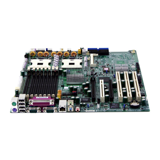
Page 9: X6Da8-G/X6Dae-G/X6Da8-G2/X6Dae-G2 Image
Chapter 1: Introduction Figure 1-1. X6DA8-G/X6DAE-G/X6DA8-G2/X6DAE-G2 Image *Notes: The differences between these models are: 1.SCSI is available for the X6DA8-G/X6DA8-G2 only. 2. There are two Gigabit LAN ports on the X6DA8-G2/X6DAE-G2 and only one Gigabit LAN on the X6DA8-G and the X6DAE-G. - Page 10 4. SCSI is available for the X6DA8-G/X6DA8-G2 only. 5. There are two Gigabit LAN ports on the X6DA8-G2/X6DAE-G2 and only one Gigabit LAN on the X6DA8-G and the X6DAE-G. 6. The graphics shown in this manual were based upon the latest PCB Revision available at the time of publishing of this manual.
-
Page 11: Quick Reference
IPMI 2.0 Connector System Management Bus Connector Parallel (Printer) Port PWR System Management Bus JA1, JA2 Ultra 320 SCSI Channel A,Channel B(X6DA8-G/G2) JBT1 CMOS Clear (JBT1 is a pad:See Chapter 2) PWR LED (Pins1-3), Speaker (Pins 4-7) Front Panel Control... -
Page 12: Motherboard Features
MHz front side (system) bus speed. speed is set by Manufacturer. Please refer to the support section of our web site for a complete listing of supported processors (http://www.supermicro.com/TechSupport.htm.) M e m o r y • Eight 240-pin DIMM sockets supporting up to 16 GB Registered ECC DDR2-400 (PC3200) SDRAM (*X6DA8-G2/X6DAE-G2 only) •... - Page 13 • Slow blinking LED for suspend state indicator • Main switch override mechanism Onboard I/O • Adaptec 7902 dual channel Ultra 320 SCSI (*X6DA8-G/X6DA8-G2 only) • One IPMI 2.0 • One Intel 8254x Gigabit Ethernet controller(*X6DA8/X6DAE-G:1 LAN, X6DA8/X6DAE-G2:2 LAN ports) •...
- Page 14 X6DA8-G/X6DAE-G/X6DA8-G2/X6DAE-G2 User's Manual 1 PCI - X S L OT 1 J 12 1 PCI - X S L OT 2 J 13 S CS I PCI - X BUS ( 100 M HZ) 7902 PCI - X BUS ( 100 M HZ)
-
Page 15: Chipset Overview
Chipset Overview Built upon the functionality and the capability of the E7525 Tumwater chipset, the X6DA8-G/X6DAE-G/X6DA8-G2/X6DAE-G2 motherboard pro- vides the performance and feature set required for dual processor-based computer systems, with configuration options optimized for communications, presentation, storage, computation or database applications. The Intel E7525... -
Page 16: Special Features
X6DA8-G/X6DAE-G/X6DA8-G2/X6DAE-G2 User's Manual Special Features Recovery from AC Power Loss BIOS provides a setting for you to determine how the system will respond when AC power is lost and then restored to the system. You can choose for the system to remain powered off (in which case you must hit the power switch to turn it back on) or for it to automatically return to a power- on state. -
Page 17: 1-5 Acpi Features
damage to the CPU. The onboard chassis thermal circuitry can monitor the overall system temperature and alert users when the chassis temperature is too high. CPU Fan Auto-Off in Sleep Mode The CPU fan activates when the power is turned on. It continues to operate when the system enters Standby mode. -
Page 18: Power Supply
It is even more important for processors that have high CPU clock rates. The SUPER X6DA8-G/X6DAE-G/X6DA8-G2/X6DAE-G2 accommodates ATX power supplies. Although most power supplies generally meet the specifi- cations required by the CPU, some are inadequate. -
Page 19: Super I/O
that will supply at least 400W of power (*Note: the 12V 8-pin power connector (J1D1) is required for CPU power consumption, and an additional 12V 4-pin power ensure adequate power supply to the system.) Also your power sup- ply must supply 1.5A for the Ethernet ports. It is strongly recommended that you use a high quality power supply that meets ATX power supply Specifi- cation 2.02 or above. - Page 20 X6DA8-G/X6DAE-G/X6DA8-G2/X6DAE-G2 User's Manual Notes 1-14...
-
Page 21: Chapter 2: Installation
Static-Sensitive Devices Electric-Static-Discharge (ESD) can damage electronic components. To pre- vent damage to your system board, it is important to handle it very carefully. The following measures are generally sufficient to protect your equipment from ESD. Precautions • Use a grounded wrist strap designed to prevent static discharge. •... -
Page 22: Nocona Processor And Heatsink Installation
X6DA8-G/X6DAE-G/X6DA8-G2/X6DAE-G2 User's Manual Nocona Processor and Heatsink Installation When handling the processor package, avoid placing direct pressure on the label area of the fan. Also, do not place the motherboard on a conductive surface, which can damage the BIOS battery and prevent the system from booting up. - Page 23 2. Insert the CPU in the socket, mak- ing sure that pin 1 of the CPU aligns with pin 1 of the socket (both cor- ners are marked with a triangle). When using only one CPU, install it into CPU socket #1 (socket #2 is au- tomatically disabled if only one CPU is used).
- Page 24 X6DA8-G/X6DAE-G/X6DA8-G2/X6DAE-G2 User's Manual To Un-install the Heatsink (Caution! We do not recommend that the CPU or the heatsink be removed. However, if you do need to un-install the heatsink, please fol- low the instructions below to uninstall the heatsink to prevent damage done to the CPU or the CPU socket.
- Page 25 Triangle Mounting the Motherboard in the Chassis All motherboards have standard mounting holes to fit different types of chassis. Make sure that the locations of all the mounting holes for both the motherboard and the chassis match. Although a chassis may have both plastic and metal mounting fasteners, metal ones are highly recommended because they ground the motherboard to the chassis.
-
Page 26: Installing Dimms
Memory Support The X6DA8-G2/X6DAE-G2 supports up to 16 GB of Reg. ECC DDR2 400 (PC3200) memory. The X6DA8-G/X6DAE-G supports up to 32 GB of Regis- tered ECC DDR 333/266 (PC2700/PC2100) memory. (*The motherboard sup- ports up to 32GB for PC2100, 16 GB for PC 2700.) *Note: A maximum of four dual rank DDR 333 memory modules are supported. -
Page 27: I/Oports/Control Panel Connectors
See Figure 2-3 below for the colors and locations of the various I/O ports. USB#0-3 KB/Mouse USB#0-3 KB/Mouse Figure 2-3. I/O Port Locations and Definitions *X6DA8-G/X6DAE-G Parallel Port COM1 & COM2 Parallel Port COM1 & COM2 *X6DA8-G2/X6DAE-G2 Chapter 2: Installation... - Page 28 JF1 contains header pins for various buttons and indicators that are nor- mally located on a control panel at the front of the chassis. These connec- tors are designed specifically for use with Supermicro server chassis. See Figure 2-4 for the descriptions of the various control panel buttons and LED indicators.
-
Page 29: Connecting Cables
Connecting Cables ATX Power Connector There are a 24-pin main power supply connector(PW1:J1B4) and a 4-pin CPU PWR connector (J32) on the board. These power con- nectors meet the SSI EPS 12V specification. You can also use a 20-pin PWR supply; however, the 4-pin 12V PWR supply is required to ensure sufficient power supply. -
Page 30: Nmi Button
X6DA8-G/X6DAE-G/X6DA8-G2/X6DAE-G2 User's Manual NMI Button The non-maskable interrupt button header is located on pins 19 and 20 of JF1. Refer to the table on the right for pin definitions. Power LED The Power LED connection is lo- cated on pins 15 and 16 of JF1. -
Page 31: Hdd Led
HDD LED The HDD LED connection is located on pins 13 and 14 of JF1. Attach the hard drive LED cable here to display disk activity (for any hard drives on the system, including SCSI, Serial ATA and IDE). the table on the right for pin defini- tions. -
Page 32: Overheat Led
X6DA8-G/X6DAE-G/X6DA8-G2/X6DAE-G2 User's Manual Overheat/Fan Fail LED Connect an LED to the OH/Fan Fail connection on pins 7 and 8 of JF1 to provide advanced warning of chassis overheating. This LED will blink to indicate a fan failure. fer to the table on the right for pin definitions. -
Page 33: Reset Button
Reset Button The Reset Button connection is lo- cated on pins 3 and 4 of JF1. At- tach it to the hardware reset switch on the computer case. Refer to the table on the right for pin definitions. Power Button The Power Button connection is located on pins 1 and 2 of JF1. -
Page 34: Chassis Intrusion
X6DA8-G/X6DAE-G/X6DA8-G2/X6DAE-G2 User's Manual Chassis Intrusion A Chassis Intrusion header is lo- cated at JL1. Attach the appropri- ate cable from chassis to inform you of a chassis intrusion. Universal Serial Bus (USB) There are eight USB 2.0 (Universal Serial Bus) ports/headers on the motherboard. -
Page 35: Atx Ps/2 Keyboard And Mouse Ports
See the table on the right for pin definitions.) Fan Headers There are eight fan headers (Fan 1 to Fan 8) on the X6DA8-G/ X6DAE-G/X6DA8-G2/X6DAE-G2. See the table on the right for pin definitions. (*Note: These fan headers are 4-pin fans. Pins 1-3... -
Page 36: Wake-On-Ring
X6DA8-G/X6DAE-G/X6DA8-G2/X6DAE-G2 User's Manual Wake-On-Ring The Wake-On-Ring header is des- ignated JWOR1. This function al- lows your computer to receive and be awakened by an incoming call to the modem when in suspend state. See the table on the right for pin definitions. You must have a Wake-On-Ring card and cable to use this feature. -
Page 37: Glan (Ethernet Port)
This port accepts RJF1 type cables. (*There are two GLAN ports for the X6DA8-G2/ X6DAE-G2 and one GLAN port for the X6DA8-G/X6DAE-G.) Power LED/Speaker On the JD1 header, pins 1-3 are for a power LED and pins 4-7 are for the speaker. -
Page 38: Power Fault
X6DA8-G/X6DAE-G/X6DA8-G2/X6DAE-G2 User's Manual Power Fault Connect a cable from your power supply to the Power Fail header (JP12) to provide warning of power supply failure. ing signal is passed through the PWR_LED pin to indicate of a power failure on the chassis. See the table on the right for pin defini- tions. -
Page 39: Smb
System Management header is located at J22. Connect the appropriate cable here to uti- lize SMB on your system. Overheat LED/Fan Fail (JOH1) The JOH1 header is used to con- nect an LED to provide warning of chassis overheating. This LED will blink to indicate a fan failure. -
Page 40: Ac'97 Audio Enable
X6DA8-G/X6DAE-G/X6DA8-G2/X6DAE-G2 User's Manual SMB Power (I Connector C Connector (J24), located be- tween the PWR ForceOn Header and the PWR Fault header, moni- tors the status of PWR Supply, Fan and system temperature. AC'97 Output & Audio Enable AC'97 provides high quality onboard audio. -
Page 41: Keylock
Keylock The keyboard lock connection is lo- cated on JK1. Utilizing this header allows you to inhibit any actions made on the keyboard, effectively "locking" it. Serial Ports The COM1 (J3) and COM2 (J4) se- rial ports are located under the parallel port (see Figure 2-3). -
Page 42: Jumper Settings
X6DA8-G/X6DAE-G/X6DA8-G2/X6DAE-G2 User's Manual Jumper Settings Explanation of Jumpers To modify the operation of the motherboard, jumpers can be used choose optional settings. create shorts between two pins to change the function of the connector. Pin 1 is identified with a square solder pad on the printed circuit board. -
Page 43: Power Failure
Power Failure The system can notify you in the event of a power supply failure. This feature assumes that three power supply units are installed in the chassis, with one acting as a backup. If you only have one or two power supply units installed, you should disable this (the default setting) with JP14 to prevent false... -
Page 44: Cmos Clear
X6DA8-G/X6DAE-G/X6DA8-G2/X6DAE-G2 User's Manual CMOS Clear JBT1 is used to clear CMOS. contact pads to prevent the accidental clearing of CMOS. To clear CMOS, use a metal object such as a small screwdriver to touch both pads at the same time to short the connection. -
Page 45: Scsi Control Enable
SCSI Controller Enable/ Disable (*ForX6DA8-G/ X6DA8-G2 only) Jumper JPA1 allows you to enable or disable the SCSI headers. default setting is pins 1-2 to enable all four headers. See the table on the right for jumper settings. SCSI Termination Enable/ Disable (*ForX6DA8-G/ X6DA8-G2 only) Jumpers JPA2 and JPA3 allow you... -
Page 46: Pllsel Select
X6DA8-G/X6DAE-G/X6DA8-G2/X6DAE-G2 User's Manual PLLSEL Select (*For XDA8- G/X6DAE-G 0nly) XJ4F1/XJ4F2 allows the user to select PLLSEL (memory speed). See the table on the right for jumper definitions. Closed: 333 MHz) PLLSEL Select 4-pin A T X P W R J P F... -
Page 47: Onboard Indicators
Onboard Indicators GLAN LEDs (*X6DA8/E-G2) The Gigabit Ethernet LAN ports has two LEDs. The left LED indi- cates activity while the right LED may be green, amber or off to indi- cate the speed of the connection. See the table at right for the func- tions associated with the second LED. -
Page 48: Parallel Port, Floppy/Hard Disk Drive And Scsi Connections
X6DA8-G/X6DAE-G/X6DA8-G2/X6DAE-G2 User's Manual Parallel Port, Floppy/Hard Disk Drive and SCSI Connections Note the following when connecting the floppy and hard disk drive cables: • The floppy disk drive cable has seven twisted wires. • A red mark on a wire typically designates the location of pin 1. -
Page 49: Floppy Connector
Floppy Connector The floppy connector is located on JP8. See the table below for pin definitions. IDE Connectors There are no jumpers to configure the onboard IDE#1 and #2 connectors (at J3 and J4, respectively). the table on the right for pin definitions. -
Page 50: Scsi Connectors
X6DA8-G/X6DAE-G/X6DA8-G2/X6DAE-G2 User's Manual Ultra320 SCSI Connectors (*X6DA8-G/X6DA8-G2 Only) Refer to the table below for the pin definitions of the Ultra320 SCSI connectors located at JA1, JA2. 4-pin A T X P W R FAN7 Fan6 Fan5 P W R Force... -
Page 51: Chapter 3: Troubleshooting
2. Use the speaker to determine if any beep codes exist. Appendix for details on beep codes. 3. Make sure that memory speeds and jumper settings are set correctly. (*X6DA8-G/X6DAE-G only) Chapter 3 Troubleshooting Chapter 3: Troubleshooting If you have... -
Page 52: Memory Errors
X6DA8-G/X6DAE-G/X6DA8-G2/X6DAE-G2 User's Manual If you are a system integrator, VAR or OEM, a POST diagnos- tics card is recommended. For I/O port 80h codes, refer to Memory Errors 1. Make sure the DIMM modules are properly and fully installed. 2. Determine if different speeds of DIMMs have been installed and verify that the BIOS setup is configured for the fastest speed of RAM used. -
Page 53: Frequently Asked Questions
Answer: The X6DA8-G2/X6DAE-G2 has eight 240-pin DIMM slots that sup- port registered ECC DDR2 400 (PC3200) SDRAM modules. However, the X6DA8-G/X6DAE-8 has eight 184-pin DIMM slots that support registered ECC DDR 333/266 (PC2700/PC2100) SDRAM modules. It is strongly recom- mended that you do not mix memory modules of different speeds and sizes. -
Page 54: Returning Merchandise For Service
X6DA8-G/X6DAE-G/X6DA8-G2/X6DAE-G2 User's Manual function available for the motherboard. Should a problem occur after you flash the BIOS, you will need to change the BIOS chip.) Question: What's on the CD that came with my motherboard? Answer: The supplied compact disc has quite a few drivers and programs that will greatly enhance your system. -
Page 55: Chapter 4: Bios
Introduction This chapter describes the Phoenix BIOS™ Setup utility for the X6DA8-G/ X6DAE-G/X6DA8-G2/X6DAE-G2. The Phoenix ROM BIOS is stored in a flash chip and can be easily upgraded using a floppy disk-based program. Note: Due to periodic changes to the BIOS, some settings may have been added or deleted and might not yet be recorded in this manual. -
Page 56: Running Setup
X6DA8-G/X6DAE-G/X6DA8-G2/X6DAE-G2 User's Manual Running Setup *Default settings are in bold text unless otherwise noted. The BIOS setup options described in this section are selected by choos- ing the appropriate text from the main BIOS Setup screen. All displayed text is described in this section, although the screen display is often all you need to understand how to set the options (see on next page). -
Page 57: Main Bios Setup Menu
Chapter 4: Phoenix BIOS Main BIOS Setup Menu Main Setup Features System Time To set the system date and time, key in the correct information in the appropriate fields. Then press the <Enter> key to save the data. System Date Using the arrow keys, highlight the month, day and year fields and enter the correct data. - Page 58 X6DA8-G/X6DAE-G/X6DA8-G2/X6DAE-G2 User's Manual Legacy Diskette A This setting allows the user to set the type of floppy disk drive installed as diskette A. The options are Disabled, 360Kb 5.25 in, 1.2MB 5.25 in, 720Kb 3.5 in, 1.44/1.25MB, 3.5 in and 2.88MB 3.5 in.
- Page 59 Chapter 4: Phoenix BIOS Type Selects the type of IDE hard drive. The options are Auto (allows the BIOS to automatically determine the hard drive's capacity, number of heads, etc.), a number from 1-39 to select a predetermined type of hard drive, CD-ROM and ATAPI Removable.
- Page 60 X6DA8-G/X6DAE-G/X6DA8-G2/X6DAE-G2 User's Manual LBA (Large Block Addressing) Mode Control If set to enabled, this feature allows a PC computer to access hard disk drives larger than 528MB. The options are Disabled and Enabled. 32 Bit I/O This option allows the user to enable or disable the function of 32-bit datea transfer.
-
Page 61: Advanced Setup
Advanced Setup Choose Advanced from the Phoenix BIOS Setup Utility main menu with the arrow keys. You should see the following display. The items with a triangle beside them have sub menus that can be accessed by highlighting the item and pressing <Enter>. - Page 62 X6DA8-G/X6DAE-G/X6DA8-G2/X6DAE-G2 User's Manual ACPI Mode Use the setting to determine if you want to employ ACPI (Advanced Configuration and Power Interface) power management on your system. The options are Yes and No. ACPI Sleep Mode Selects the sleep mode for ACPI. The options are S1(-Stanby) and S3 (-Suspend to RAM).
- Page 63 Chapter 4: Phoenix BIOS Memory Cache Cache System BIOS Area This setting allows you to designate a reserve area in the system memory to be used as a System BIOS buffer to allow the BIOS to write (cache) its data into this reserved memory area. Select "Write Protect" to enable this function, and this area will be reserved for the BIOS ROM access only.
- Page 64 X6DA8-G/X6DAE-G/X6DA8-G2/X6DAE-G2 User's Manual Cache Extended Memory If enabled, this feature will allow the data cached in the system memory area above 1 MB or to be cached into L1, L2, L3 cache inside the CPU to speed up CPU operations. Select "Uncached" to disable this function.
- Page 65 PCI-X 100MHz ZCR Slot#1/PCI-X 100MHz Slot#2/PCI-X 133MHz Slot#3/PCI-E X4 Slot#4/PCI 33MHz Slot#5/PCI-E X16 Slot#6 Access the submenu for each of the settings above to make changes to the following: Option ROM Scan When enabled, this setting will initialize the device expansion ROM. The options are Enabled and Disabled.
- Page 66 X6DA8-G/X6DAE-G/X6DA8-G2/X6DAE-G2 User's Manual Memory RAS Feature Control Select this option to enable Memory RAS (Reliability/ Availability/ Serviceability) Feature Control. The Options are Standard, Sparing, and Mirroring. Select Sparing (RAID 0) to increase the performance of data transfer by simultaneously writing data to two drives. Select Mirroring (RAID 1) to increase data protection by writing identical data on two drives.
- Page 67 Chapter 4: Phoenix BIOS Advanced Processor Options Access the submenu to make changes to the following settings. CPU Speed This is a display that indicates the speed of the installed processor. Hyper-threading This setting allows you to Enable or Disable the function of hyper- threading.
- Page 68 X6DA8-G/X6DAE-G/X6DA8-G2/X6DAE-G2 User's Manual I/O Device Configuration Access the submenu to make changes to the following settings. KBC Clock input This setting allows you to set the clock frequency for the Keyboard Clock. The options are 6MHz, 8MHz, and 12 MHz.
- Page 69 Base I/O Address This setting allows you to select the base I/O address for the parallel port. The options are 378, 278 and 3BC. Interrupt This setting allows you to select the IRQ (interrupt request) for the parallel port. The options are IRQ5 and IRQ7. Mode This setting allows you to specify the parallel port mode.
- Page 70 X6DA8-G/X6DAE-G/X6DA8-G2/X6DAE-G2 User's Manual DMI Event Logging Access the submenu to make changes to the following settings. Event Log Validity This is a display, not a setting, informing you of the event log validity. Event Log Capacity This is a display, not a setting, informing you of the event log capacity.
- Page 71 Chapter 4: Phoenix BIOS Console Redirection Access the submenu to make changes to the following settings. COM Port Address This feature allows you to decide which COM port to redirect the console to: On-board COM A or On-board COM B. This setting can also be Disabled.
- Page 72 X6DA8-G/X6DAE-G/X6DA8-G2/X6DAE-G2 User's Manual Hardware Monitor Logic CPU Temperature Threshold This option allows the user to set a CPU temperature threshold that will activate the alarm system when the CPU temperature reaches this pre-set temperature threshold. The options are 85 Highlight this and hit <Enter> to see monitor data for the following items: CPU1 Temperature: This item displays CPU1 Temperature.
- Page 73 Chapter 4: Phoenix BIOS Security Choose Security from the Phoenix BIOS Setup Utility main menu with the arrow keys. You should see the following display. Security setting options are displayed by highlighting the setting using the arrow keys and pressing <Enter>. All Security BIOS settings are described in this section.
- Page 74 X6DA8-G/X6DAE-G/X6DA8-G2/X6DAE-G2 User's Manual Set Supervisor Password When the item "Set Supervisor Password" is highlighted, hit the <Enter> key. When prompted, type the Supervisor's password in the dialogue box to set or to change supervisor's password, which allows access to the BIOS.
- Page 75 Chapter 4: Phoenix BIOS Boot Choose Boot from the Phoenix BIOS Setup Utility main menu with the arrow keys. You should see the following display. Highlighting a setting with a + or - will expand or collapse that entry. See details on how to change the order and specs of boot devices in the Item Specific Help window.
-
Page 76: Exit
X6DA8-G/X6DAE-G/X6DA8-G2/X6DAE-G2 User's Manual Exit Choose Exit from the Phoenix BIOS Setup Utility main menu with the arrow keys. You should see the following display. All Exit BIOS settings are described in this section. Exit Saving Changes Highlight this item and hit <Enter> to save any changes you made and to exit the BIOS Setup utility. - Page 77 Chapter 4: Phoenix BIOS Discard Changes Highlight this item and hit <Enter> to discard (cancel) any changes you made. You will remain in the Setup utility. Save Changes Highlight this item and hit <Enter> to save any changes you made. You will remain in the Setup utility.
- Page 78 X6DA8-G/X6DAE-G/X6DA8-G2/X6DAE-G2 User's Manual Notes 4-24...
-
Page 79: Recoverable Post Errors
BIOS POST Codes This section lists the POST (Power On Self Test) codes for the PhoenixBIOS. POST codes are divided into two categories: recoverable and terminal. Recoverable POST Errors When a recoverable type of error occurs during POST, the BIOS will display an POST code that describes the problem. - Page 80 X6DA8-G/X6DAE-G/X6DA8-G2/X6DAE-G2 User's Manual POST Code Description 8254 timer initialization 8237 DMA controller initialization Reset Programmable Interrupt Controller 1-3-1-1 Test DRAM refresh 1-3-1-3 Test 8742 Keyboard Controller Set ES segment register to 4 GB Auto size DRAM Initialize POST Memory Manager...
- Page 81 POST Code Description Test RAM between 512 and 640 kB Test extended memory Test extended memory address lines Jump to UserPatch1 Configure advanced cache registers Initialize Multi Processor APIC Enable external and CPU caches Setup System Management Mode (SMM) area Display external L2 cache size Load custom defaults (optional) Display shadow-area message...
- Page 82 X6DA8-G/X6DAE-G/X6DA8-G2/X6DAE-G2 User's Manual POST Code Description Check for SMART Drive (optional) Shadow option ROMs Set up Power Management Initialize security engine (optional) Enable hardware interrupts Determine number of ATA and SCSI drives Set time of day Check key lock Initialize typematic rate...
- Page 83 POST Code Description Re-map I/O and memory for PCMCIA Initialize digitizer and display message Unknown interrupt The following are for boot block in Flash ROM POST Code Description Initialize the chipset Initialize the bridge Initialize the CPU Initialize system timer Initialize system I/O Check force recovery boot Checksum BIOS ROM...
- Page 84 X6DA8-G/X6DAE-G/X6DA8-G2/X6DAE-G2 User's Manual Notes...
- Page 85 After all the hardware has been installed, you must first configure the Adaptec Embedded Serial ATA RAID Driver before you install the Windows operating system. The necessary drivers are all included on the Supermicro bootable CDs that came packaged with your motherboard.
-
Page 86: Configuring Bios Settings For The Sata Raid Functions
X6DA8-G/X6DAE-G/X6DA8-G2/X6DAE-G2 User's Manual Configuring BIOS settings for the SATA RAID Functions 1. Press the <Del> key during system bootup to enter the BIOS Setup Utility. (*Note: If it is the first time to power on the system, we recommend that you load the Optimized Default Settings. - Page 87 Adaptec RAID Controller User's Guide: "Emb_SA_RAID_UG.pdf" in the CD that came with this motherboard. You can also download a copy of Adaptec's User's Guide from our web site at www.supermicro.com.) Using the Adaptec RAID Configuration Utility (ARC) The Adaptec RAID Configuration Utility is an embedded BIOS Utility, includ-...
- Page 88 X6DA8-G/X6DAE-G/X6DA8-G2/X6DAE-G2 User's Manual Managing Arrays Select this option to view array properties, and delete arrays. The following sections describe the operations Of "Managing Arrays". To select this option, use the arrow keys and the <enter> key to select "Managing Arrays" from the main menu (as shown above).
- Page 89 Viewing Array Properties To view the properties of an existing array: 1. At the BIOS prompt, press Ctrl+A. 2. From the ARC menu, select Array Configuration Utility (ACU). 3. From the ACU menu, select Manage Arrays (as shown on the previous screen.) 4.
- Page 90 X6DA8-G/X6DAE-G/X6DA8-G2/X6DAE-G2 User's Manual Creating Arrays Before creating arrays, make sure the disks for the array are connected and installed in your system. Note that disks with no usable space, or disks that are un-initialized are shown in gray and cannot be used. See Initializ- ing Disk Drives.
- Page 91 Appendix B: Software Installation Instructions Assigning Array Properties Once you've create a new array, you are ready to assign the properties to the array. *Caution: Once the array is created and its properties are assigned, you cannot change the array properties using the ACU. You will need to use the Adaptec Storage Manager - Browser Edition.
- Page 92 X6DA8-G/X6DAE-G/X6DA8-G2/X6DAE-G2 User's Manual 2. Under the item "Arrays Label", (*Note: The label shall not be more than 15 characters.) 3. For RAID 0, select the desired stripe size. (*Note: Available stripe sizes are 16, 32, and 64 KB-default. It is recommended that you do not change the default setting.)
- Page 93 Appendix B: Software Installation Instructions 5. When you are finished, press Done (as the screen shown below). Notes: 1. Before adding a new drive to an array, back up any data contained on the new drive. Otherwise, all data will be lost. 2.
- Page 94 X6DA8-G/X6DAE-G/X6DA8-G2/X6DAE-G2 User's Manual Adding a Bootable Array To make an array bootable: 1. From the Main menu, select Manage Arrays. 2. From the List of Arrays, select the array you want to make bootable, and press Ctrl+B. 3. Enter Y to create a bootable array when the following message is displayed: "This will make all other existing bootable array non-bootable.
- Page 95 Appendix B: Software Installation Instructions Adding/Deleting Hotspares (*Note: In order to rebuild a RAID (RAID 0 or RAID 1), you would need to add a new HDD as a hotspare.) 1. Turn on your computer and press Ctrl+A as prompted to access the ARC Utility.
-
Page 96: Initializing Disk Drives
X6DA8-G/X6DAE-G/X6DA8-G2/X6DAE-G2 User's Manual Initializing Disk Drives If an installed disk does not appear in the disk selection list for creating a new array, or if it appears grayed out, you may have to initialize it before you can use it as part of an array. Drives attached to the controller must be initialized before they can be used in an array. - Page 97 Appendix B: Software Installation Instructions 4. Use the up and down arrow keys to highlight the disk you wish to initialize and press Insert (as shown in the screen below). B-13...
- Page 98 X6DA8-G/X6DAE-G/X6DA8-G2/X6DAE-G2 User's Manual 5. Repeat Step 4 so that both drives to be initialized are selected (as shown in the screen below). 6. Press Enter. 7. Read the warning message as shown in the screen. 8. Make sure that you have selected the correct disk drives to initialize.
- Page 99 Appendix B: Software Installation Instructions Rebuilding Arrays *Note 1: Rebuilding applies to Fault Tolerant array (RAID 1) only. If an array Build process (or initialization) is interrupted or critical with one member missing, you must perform a Rebuild to optimized its functionality. For a critical array Rebuild operation, the optimal drive is the source drive.
-
Page 100: Using The Disk Utilities
X6DA8-G/X6DAE-G/X6DA8-G2/X6DAE-G2 User's Manual Using the Disk Utilities The Disk Utilities enable you to format or verify the media of your Serial ATA hard disks. To access the disk utilities: 1. Turn on your computer and press Ctrl+A when prompted to access the ARC utility (as shown in the screen below.) - Page 101 Appendix B: Software Installation Instructions 2. From the ARC menu, select Disk Utilities as shown in the screen below. 3 Select the desired disk and press Enter (as shown in the screen below.) B-17...
- Page 102 (*For more information regarding Adaptec RAID Utility, please refer to Adaptec's User's Guide in the CD included in your shipping pack- age. You can also download a copy of Adaptec User's Guide from our web site at: www. supermicro.com.) B-18...
- Page 103 Appendix B: Software Installation Instructions B-2 Installing Intel's ICH5R Driver by Adaptec and Windows Operating System a. Insert Supermicro's bootable CD that came with the package into the CD Drive during the system reboot, and the screen:"Super Micro Driver Diskette Maker" will appear.
- Page 104 X6DA8-G/X6DAE-G/X6DA8-G2/X6DAE-G2 User's Manual B-3 Installing Other Software Programs and Drivers A. Installing Drivers other than Adaptec Embedded Serial ATA RAID Controller Driver After you've installed the Windows Operating System, a screen as shown below will appear. You are ready to install software programs and drivers that have not yet been installed.
- Page 105 Appendix B: Software Installation Instructions Supero Doctor III The Supero Doctor III program is a Web-base management tool that supports remote management capability. It includes Remote and Local Management tools. The local management is called the SD III Client. The Supero Doctor III program included on the CDROM that came with your motherboard allows to monitor the environment and operations of your system.
- Page 106 Supero Doctor III Interface Display Screen-II (Remote Control) *Note: SD III Software Revision 1.0 can be downloaded from our Web site at: ftp://ftp.supermicro.com/utility/Supero_Doctor_III/. You can also down- load SDIII User's Guide at: http://www.supermicro.com/PRODUCT/Manuals/ SDIII/UserGuide.pdf. For Linux, we will still recommend Supero Doctor II. B-22...
Need help?
Do you have a question about the X6DA8-G and is the answer not in the manual?
Questions and answers