Table of Contents
Advertisement
Quick Links
Advertisement
Table of Contents

Subscribe to Our Youtube Channel
Related Manuals for Vega VEGAMIP R62


Summary of Contents for Vega VEGAMIP R62
- Page 1 Operating Instructions VEGAMIP R62 Receiving unit Transistor Document ID: 41911...
-
Page 2: Table Of Contents
How to proceed if a repair is necessary ................38 Dismount..........................39 Dismounting steps......................39 Disposal ......................... 39 Supplement ..........................40 Technical data ........................ 40 Dimensions ........................44 Industrial property rights ....................48 Trademark ........................48 VEGAMIP R62 • Receiving unit... - Page 3 Contents Safety instructions for Ex areas Take note of the Ex specific safety instructions for Ex applications. These instructions are attached as documents to each instrument with Ex approval and are part of the operating instructions. Editing status: 2020-05-20 VEGAMIP R62 • Receiving unit...
-
Page 4: About This Document
Symbols used Document ID This symbol on the front page of this instruction refers to the Docu- ment ID. By entering the Document ID on www.vega.com you will reach the document download. Information, note, tip: This symbol indicates helpful additional infor- mation and tips for successful work. -
Page 5: For Your Safety
K band range. The low transmitting power lies far below the internationally permitted limit value. When the instrument is used correctly, it presents no danger to human health. It may be operated without restriction outside of closed vessels. VEGAMIP R62 • Receiving unit... -
Page 6: Eu Conformity
That is why we have introduced an environment management system with the goal of continuously improving company environmental pro- tection. The environment management system is certified according to DIN EN ISO 14001. Please help us fulfil this obligation by observing the environmental instructions in this manual: • Chapter "Packaging, transport and storage" • Chapter "Disposal" VEGAMIP R62 • Receiving unit... -
Page 7: Product Description
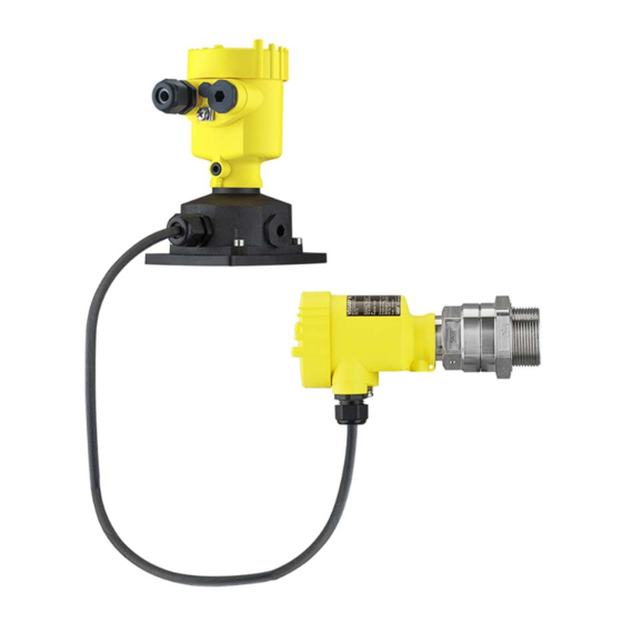
Alternatively, you can access the data via your smartphone: • Download the VEGA Tools app from the "Apple App Store" or the "Google Play Store" • Scan the DataMatrix code on the type label of the instrument or •... - Page 8 The VEGAMIP consists of an emitting unit VEGAMIP T61 and a receiving unit VEGAMIP R62 with external housing. Fig. 1: VEGAMIP 62 with plastic housing Emitting unit VEGAMIP T61...
-
Page 9: Packaging, Transport And Storage
Up to the time of installation, the packages must be left closed and stored according to the orientation and storage markings on the outside. Unless otherwise indicated, the packages must be stored only under the following conditions: • Not in the open VEGAMIP R62 • Receiving unit... -
Page 10: Accessories
The mounting adapter "High temperature" can only be used with the threaded version (internal horn antenna with PTFE cover). Fig. 4: VEGAMIP 62 with mounting adapter "High temperature" -40 … +450 °C (-40 … +842 °F) Length: Mounting adapter "High temperature" VEGAMIP R62 • Receiving unit... - Page 11 40, 60, 80 100 and 150 mm (1.57, 2.36, 3.15, 3.94, 5.91 in). Fig. 5: VEGAMIP 62 with mounting adapter "High temperature with extension" -40 … +450 °C (-40 … +842 °F) VEGAMIP R62 • Receiving unit...
-
Page 12: Mounting
Make sure that during installation or maintenance no moisture or dirt can get inside the instrument. To maintain the housing protection, make sure that the housing lid is closed during operation and locked, if necessary. VEGAMIP R62 • Receiving unit... -
Page 13: Mounting Instructions
Some exemplary reference values for the min. strength of the me- dium: Medium type Medium Min. medium thickness Plastic granules PTFE, PS > 1000 mm PP, PE, HDPE, POM > 500 mm PA, PVC, PVDF > 250 mm VEGAMIP R62 • Receiving unit... - Page 14 Max. thickness of the window material: Type of material Window material Max. thickness Plastics PTFE, PS < 5000 mm PP, PE, HDPE, POM < 1000 mm PA, PVC, PVDF < 500 mm Rubber < 50 mm VEGAMIP R62 • Receiving unit...
- Page 15 Pipelines VEGAMIP 62 can be used for detection of products in pipelines. In pipelines of non-metallic products such as plastic or glass, the meas- ured product can be detected through the pipe wall. VEGAMIP R62 • Receiving unit...
- Page 16 Note: In the case of VEGAMIP 62 with NPT thread, the instrument seals in the thread itself. Hence, no counter nut is necessary for these ver- sions. VEGAMIP R62 • Receiving unit...
- Page 17 Select the material according to the diameter of the socket and adapt the length as far as possible to the shape of the vessel wall. Secure the filling material against falling out or turning. If using a fixing screw is technically not possible, you can secure the material in the socket with an adhesive. VEGAMIP R62 • Receiving unit...
- Page 18 This mounting adapter "Abrasion protection" is screwed onto the thread of VEGAMIP 62 like an adapter. The mounting adapter "Abrasion protection" can only be used with the threaded version (internal horn antenna with PTFE cover) VEGAMIP R62 • Receiving unit...
- Page 19 As an option, the "high temperature" mounting adapter can be also equipped with an extension for front-flush mounting. Thus the instru- ment can also be mounted into long sockets where there is danger of buildup in the socket. The extension is available in five lengths: 40, 60, 80, 100 and 150 mm (1.57, 2.36, 3.15, 3.94, 5.91 in). VEGAMIP R62 • Receiving unit...
- Page 20 To get an optimal switching signal, the two sensors must be aligned to each other. The accuracy must be in a range of ±5°. Axis offset The axes of the two sensors can be offset up to < 5% of the sensor distance (d) from each other. Example: with a distance of 1000 mm VEGAMIP R62 • Receiving unit...
- Page 21 For a reliable function, the emitting and receiving units must be installed in the same polarisation direction. If multiple instrument pairs are installed in one vessel, the instrument pairs can be coded, so to speak, by mounting them in different polari- sation positions so that they do not influence one another. VEGAMIP R62 • Receiving unit...
- Page 22 On instrument versions with detach- able horn antenna, the antenna extension can be retrofitted. To minimize false echoes, take note of the polarisation plane. Keep the position of the polarisation marking with respect to the antenna extension in mind. Mount the antenna extension according to the fol- lowing illustration. VEGAMIP R62 • Receiving unit...
- Page 23 The base of stainless steel can be displaced in 90° increments on the wall mounting plate, the base of plastic by 180°. Turn the cable gland of the electronics housing downward. The hous- ing can be turned by 330° without the use of any tools. VEGAMIP R62 • Receiving unit...
- Page 24 4 Mounting Warning: With the plastic housing, the four screws of the base may only be screwed in hand tight. Exceeding the max. torque specified in chapter "Technical data" can damage the wall mounting plate. VEGAMIP R62 • Receiving unit...
-
Page 25: Connecting To Power Supply
In the case of instrument housings with self-sealing NPT threads, it is not possible to have the cable entries screwed in at the factory. The free openings for the cable glands are therefore covered with red dust protection caps as transport protection. VEGAMIP R62 • Receiving unit... -
Page 26: Connection Procedure
7. Connect the shielding to the internal ground terminal, connect the external ground terminal to potential equalisation 8. Tighten the compression nut of the cable entry gland. The seal ring must completely encircle the cable 9. Screw the housing lid back on The electrical connection is finished. VEGAMIP R62 • Receiving unit... - Page 27 6. Tighten the compression nut of the cable entry gland. The seal ring must completely encircle the cable 7. Place housing with base back on the mounting plate and tighten the screws The electrical connection of the sensor to the external housing is finished. VEGAMIP R62 • Receiving unit...
-
Page 28: Wiring Plan Receiving Unit
Shielding Wiring plan - Sensor housing 1 2 3 Fig. 24: Connection of the cable in the sensor housing White (terminal 6) Brown (terminal 7) Blue (terminal 8) Shielding Control lamp (LED) - Voltage supply VEGAMIP R62 • Receiving unit... - Page 29 The terminals 1 and 5 as well as 2 and 8 are internally connected. Hence PNP or NPN action can be selected through the electrical connection. Connection - PNP action Fig. 26: Wiring plan processing unit - VEGAMIP 62 (receiver) - PNP action Voltage supply Load VEGAMIP R62 • Receiving unit...
- Page 30 5 Connecting to power supply Connection - NPN action Fig. 27: Wiring plan processing unit - VEGAMIP 62 (receiver) - NPN action Voltage supply Load Connection - floating Fig. 28: Wiring plan processing unit - VEGAMIP 62 (receiver) - floating Voltage supply Auxiliary voltage VEGAMIP R62 • Receiving unit...
-
Page 31: Setup
The signal lamp signals the switching condition of the switching output. Control lamp (green) for indication of the instrument function The green signal lamp (on) shows the operating state of the instru- ment as soon as voltage supply is connected correctly. VEGAMIP R62 • Receiving unit... -
Page 32: Adjustment
(yellow) Max. mode of op- closed eration Overflow protec- tion Max. mode of op- open eration Overflow protec- tion Min. mode of op- closed eration Dry run protection Min. mode of op- open eration Dry run protection VEGAMIP R62 • Receiving unit... - Page 33 "-->" key makes the sensor less sensitive. Press the respective key until the indication is within the LED indica- tion strip. This means one or two LEDs on the LED indication strip will light up. VEGAMIP R62 • Receiving unit...
- Page 34 The indication of the LED indicating strip does not change, but the instrument will become a little less sensitive with each pressing of the key. VEGAMIP R62 • Receiving unit...
- Page 35 Fig. 32: LED indicating strip - Setting for products with weak signal damping Switching delay You can adjust the switching delay with the help of the LED indicating strip. Push the two keys (7) and (8) simultaneously for approximately 2 s until the LED indication flashes. VEGAMIP R62 • Receiving unit...
- Page 36 10 s. Simulation If possible, simulate a filling between emitting and receiving unit with your hand or a metal sheet and check if the switching point is adjusted correctly. If the control lamp changes its switching status, the switching function is correct VEGAMIP R62 • Receiving unit...
-
Page 37: Maintenance And Fault Rectification
Operate the mode switch (min./max.). If the instrument then switches mode, the sensor may be covered with buildup or mechanically damaged. If the switching function in the correct mode is faulty, re- turn the instrument for repair. VEGAMIP R62 • Receiving unit... -
Page 38: Exchanging The Electronics
24 hour service hotline Should these measures not be successful, please call in urgent cases the VEGA service hotline under the phone no. +49 1805 858550. The hotline is also available outside normal working hours, seven days a week around the clock. -
Page 39: Dismount
Pass the instrument directly on to a specialised recycling company and do not use the municipal collecting points. If you have no way to dispose of the old instrument properly, please contact us concerning return and disposal. VEGAMIP R62 • Receiving unit... -
Page 40: Supplement
Plastic housing: Polycarbonate (UL746-C listed) (optional for relay version) Metal housing: Glass Ʋ Ground terminal 316L Ʋ Cable gland PA, stainless steel, brass Ʋ Sealing, cable gland Aluminium, stainless steel precision casting and Ex d housing VEGAMIP R62 • Receiving unit... - Page 41 Flange DN 80 … DN 150, ASME 3" … 6" Torque for NPT cable glands and Conduit tubes Ʋ Plastic housing max. 10 Nm (7.376 lbf ft) Ʋ Aluminium/Stainless steel housing max. 50 Nm (36.88 lbf ft) Outside the specified beam angle, the energy of the radar signal has a level of -3 dB (50 %). VEGAMIP R62 • Receiving unit...
- Page 42 -40 … +130 °C (-40 … +266 °F) seal: FKM (SHS FDM 70C3 GLT) Ʋ VEGAMIP 62, horn antenna/316L - -20 … +130 °C (-4 … +266 °F) seal: FFKM (Kalrez 6375) Not overload resistant and not short-circuit proof Note max. pressure of the process fitting. VEGAMIP R62 • Receiving unit...
- Page 43 Ʋ External housing IP65 Ʋ Housing base - external housing IP68 (1 bar), NEMA Type 6P Overvoltage category (IEC 61010-1) The feeding power supply unit can be connected to networks of overvoltage category III. Protection class VEGAMIP R62 • Receiving unit...
-
Page 44: Dimensions
Stainless steel single chamber (electropolished) Stainless steel single chamber (precision casting) Aluminium - single chamber External housing 90 mm (3.54") 110 mm (4.33") ~ 66 mm (2.6") Fig. 35: External housing, receiving unit Instrument housing External housing VEGAMIP R62 • Receiving unit... - Page 45 SW 60 mm (1.42") 1½ NPT G1½ A Fig. 36: VEGAMIP 62, internal horn antenna (threaded version) Internal horn antenna with PTFE cover, threaded version G1½ Internal horn antenna with PTFE cover, threaded version 1½ NPT VEGAMIP R62 • Receiving unit...
- Page 46 Plastic encapsulated antenna with PP cover Mounting strap Adapter flange VEGAMIP 62, horn antenna 1½" ø40 2" ø48 SW 46 mm inch (1.81") 3.94" ø1.58" 1½" 4.72" ø1.89" 2" G1½A / 1½ NPT Fig. 38: VEGAMIP 62, horn antenna (316L) VEGAMIP R62 • Receiving unit...
- Page 47 150 mm (5.9 in), -40 … +250 °C (-40 … +482 °F) 300 mm (11.8 in), -40 … +450 °C (-40 … +842 °F) Extension length 40, 60, 80, 100 or 150 mm (1.57, 2.36, 3.15, 3.94, 5.91 in) VEGAMIP R62 • Receiving unit...
-
Page 48: Industrial Property Rights
Les lignes de produits VEGA sont globalement protégées par des droits de propriété intellec- tuelle. Pour plus d'informations, on pourra se référer au site www.vega.com. VEGA lineas de productos están protegidas por los derechos en el campo de la propiedad indus- trial. Para mayor información revise la pagina web www.vega.com. - Page 49 Orientation of the sensor 20 Pipelines 15 Polarisation direction 20 Potential equalisation 25 Receiving unit 8, 29, 31 Repair 38 Sensitivity adjustment 33 Service hotline 38 Shielding 25 Simulation 36 Switching delay 35 Switching point 13 Threaded version 16 VEGAMIP R62 • Receiving unit...
- Page 50 Notes VEGAMIP R62 • Receiving unit...
- Page 51 Notes VEGAMIP R62 • Receiving unit...
- Page 52 Subject to change without prior notice © VEGA Grieshaber KG, Schiltach/Germany 2020 VEGA Grieshaber KG Phone +49 7836 50-0 Am Hohenstein 113...
Need help?
Do you have a question about the VEGAMIP R62 and is the answer not in the manual?
Questions and answers