Vega vegacap 62 Operating Instructions Manual
Capacitive rod electrode for level detection
Hide thumbs
Also See for vegacap 62:
- Operating instructions manual (40 pages) ,
- Operating instructions manual (36 pages) ,
- Operating instructions manual (36 pages)

Related Manuals for Vega vegacap 62


Summary of Contents for Vega vegacap 62
-
Page 1: Operating Instructions
Operating Instructions Capacitive rod electrode for level detection VEGACAP 62 - two-wire Document ID: 30007... -
Page 2: Table Of Contents
Shortening of the probe ....................25 How to proceed if a repair is necessary ................25 Dismount Dismounting steps......................27 Disposal ......................... 27 Supplement Technical data ........................ 28 Dimensions ........................32 Industrial property rights ....................35 Trademark ........................35 VEGACAP 62 • - two-wire... - Page 3 Instructions manuals for accessories and replacement parts Tip: To ensure reliable setup and operation of your VEGACAP 62, we offer accessories and replacement parts. The corresponding documenta- tions are: • 30174 - Electronics module VEGACAP series 60 • 34296 - Protective cover • 31088 - Flanges according to DIN-EN-ASME-JIS-GOST Editing status: 2016-02-19 VEGACAP 62 • - two-wire...
-
Page 4: About This Document
Action This arrow indicates a single action. Sequence of actions Numbers set in front indicate successive steps in a procedure. Battery disposal This symbol indicates special information about the disposal of bat- teries and accumulators. VEGACAP 62 • - two-wire... -
Page 5: For Your Safety
During work on and with the device the required personal protective equipment must always be worn. Appropriate use The VEGACAP 62 is a sensor for point level detection. You can find detailed information about the area of application in chapter "Product description". Operational reliability is ensured only if the instrument is properly used according to the specifications in the operating instructions manual as well as possible supplementary instructions. -
Page 6: Safety Label On The Instrument
That is why we have introduced an environment management system with the goal of continuously improving company environmental pro- tection. The environment management system is certified according to DIN EN ISO 14001. Please help us fulfill this obligation by observing the environmental instructions in this manual: • Chapter "Packaging, transport and storage" • Chapter "Disposal" VEGACAP 62 • - two-wire... -
Page 7: Product Description
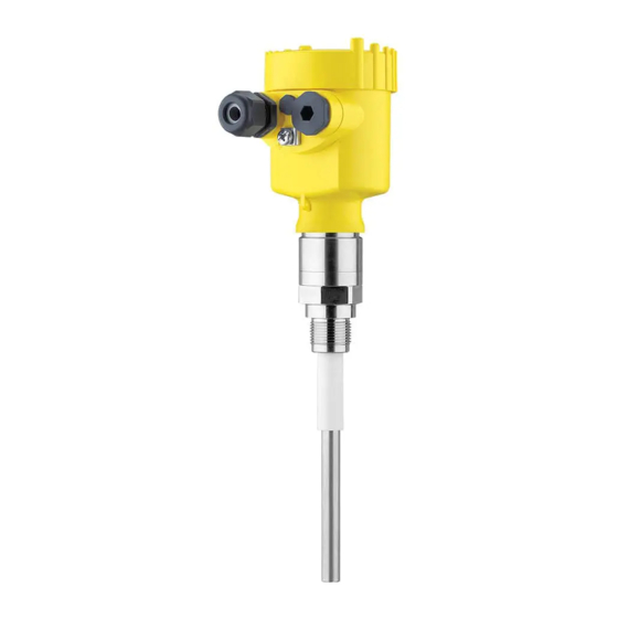
• Housing with electronics • Housing cover, optionally available with display and adjustment module Fig. 1: VEGACAP 62 - rod version with plastic housing Housing cover with integrated display and adjustment module (optional) Housing with electronics 3 Process fitting Type label... -
Page 8: Principle Of Operation
Principle of operation Area of application VEGACAP 62 is a point level sensor for use in all areas of industry. The partly insulated probe is suitable for the measurement of bulk solids and liquids. -
Page 9: Operation
The capacitance change is converted by the electronics module into a switching command. Voltage supply Depending on your requirements, VEGACAP 62 with two-wire elec- tronics can be connected to different signal conditioning instruments. Compatible signal conditioning instruments are listed in chapter "Technical data". The data for power supply are specified in chapter "Technical data". -
Page 10: Accessories And Replacement Parts
The protective cover protects the sensor housing against soiling and intense heat from solar radiation. You will find additional information in the supplementary instructions manual "Protective cover" (Document-ID 34296). Flanges Screwed flanges are available in different versions according to the following standards: DIN 2501, EN 1092-1, BS 10, ASME B 16.5, JIS B 2210-1984, GOST 12821-80. You can find additional information in the supplementary instructions manual "Flanges according to DIN-EN-ASME-JIS". VEGACAP 62 • - two-wire... -
Page 11: Mounting
Fig. 4: Measures against moisture ingress Transport Do not hold VEGACAP 62 on the probe. Especially with heavy flange versions or long rod versions, the sensor can be damaged simply by the weight of the instrument. VEGACAP 62 • - two-wire... -
Page 12: Mounting Instructions
Agitators and fluidization Due to the effects of agitators, equipment vibration or similar, the level switch can be subjected to strong lateral forces. For this reason, do not use an overly long electrode for VEGACAP 62, but check if you can mount a short level switch on the side of the vessel in horizontal position. Extreme vibration caused by the system, e.g. due to agitators or turbulence in the vessel from fluidisation, can cause the probe of VEGACAP 62 to vibrate in resonance. - Page 13 The probe must be mounted in a way that takes the arrangement of the filling and emptying apertures into account. To compensate measurement errors caused by the material cone in cylindrical vessels, the sensor must be mounted at a distance of d/6 from the vessel wall. VEGACAP 62 • - two-wire...
- Page 14 4 Mounting Fig. 6: Filling and emptying centred Fig. 7: Filling in the centre, emptying laterally VEGACAP 62 Discharge opening Filling opening VEGACAP 62 • - two-wire...
-
Page 15: Connecting To Power Supply
Proceed as follows: 1. Unscrew the housing lid 2. Loosen compression nut of the cable gland and remove blind plug 3. Remove approx. 10 cm (4 in) of the cable mantle, strip approx. 1 cm (0.4 in) of insulation from the ends of the individual wires 4. Insert the cable into the sensor through the cable entry VEGACAP 62 • - two-wire... -
Page 16: Wiring Plan, Single Chamber Housing
Wiring plan, single chamber housing Housing overview Fig. 9: Material versions, single chamber housing Plastic (not with dust-Ex) Aluminium Stainless steel Filter element for pressure compensation or blind plug with version IP 66/ IP 68, 1 bar VEGACAP 62 • - two-wire... - Page 17 The wiring example is applicable for all suitable signal conditioning instruments. Take note of the operating instructions manual of the signal condition- ing instrument. Suitable signal conditioning instruments are listed in chapter "Technical data". Fig. 11: Wiring plan Voltage supply VEGACAP 62 • - two-wire...
-
Page 18: Wiring Plan - Version Ip 66/Ip 68, 1 Bar
After connecting to voltage supply or after a voltage recurrence, the instrument passes a certain switch on routine. By lowering the current value when switching on, the instrument can output briefly a fault message. I/mA 20,5 < 2,3 Fig. 13: Warm-up reaction Measured value VEGACAP 62 • - two-wire... -
Page 19: Setup
Note: As a rule, always set the mode with the mode switch of the signal conditioning instrument before starting setup VEGACAP 62. The switching output will change if you set the mode switch afterwards. This could possibly trigger other connected instruments or devices. - Page 20 See operating instructions manual of the "Signal conditioning instru- ment". Switching point adjust- The adjustment of the switching point is only possible in installed ment condition. The detailed adjustment of VEGACAP 62 is described in the operat- ing instructions manual of the "Signal conditioning instrument". VEGACAP 62 • - two-wire...
-
Page 21: Maintenance And Fault Rectification
24 hour service hotline Should these measures not be successful, please call in urgent cases the VEGA service hotline under the phone no. +49 1805 858550. The hotline is manned 7 days a week round-the-clock. Since we offer this service worldwide, the support is only available in the English language. The service is free, only standard call charges are incurred. - Page 22 Check the resistance in Remove the electronics module. Check the resistance between the the probe two plug connections. There must no longer be a connection (high impedance). If there is still a connection - exchange the instrument or return it for repair VEGACAP 62 • - two-wire...
-
Page 23: Exchange Of The Electronics Module
Downloads. Proceed as follows: 1. Switch off power supply 2. Unscrew the housing lid 3. Lift the opening levers of the terminals with a screwdriver 4. Pull the connection cables out of the terminals 5. Loosen the two screws with a screw driver (Torx size T10 or slot VEGACAP 62 • - two-wire... - Page 24 13. Check the hold of the wires in the terminals by lightly pulling on them 14. Check cable gland on tightness. The seal ring must completely encircle the cable. 15. Mount the probe into the vessel. Make sure that the probe is uncovered. VEGACAP 62 • - two-wire...
-
Page 25: Shortening Of The Probe
By doing this you help us carry out the repair quickly and without hav- ing to call back for needed information. If a repair is necessary, please proceed as follows: • Print and fill out one form per instrument VEGACAP 62 • - two-wire... - Page 26 Clean the instrument and pack it damage-proof • Attach the completed form and, if need be, also a safety data sheet outside on the packaging • Please contact the agency serving you to get the address for the return shipment. You can find the agency on our home page www.vega.com. VEGACAP 62 • - two-wire...
-
Page 27: Dismount
These may be used only for privately used products according to the WEEE directive. Correct disposal avoids negative effects on humans and the environ- ment and ensures recycling of useful raw materials. Materials: see chapter "Technical data" If you have no way to dispose of the old instrument properly, please contact us concerning return and disposal. VEGACAP 62 • - two-wire... -
Page 28: Supplement
½ NPT, ¾ NPT, 1 NPT, 1½ NPT (ASME B1.20.1) Ʋ Flanges DIN from DN 25, ASME from 1" Weight Ʋ Instrument weight (depending on 0.8 … 4 kg (0.18 … 8.82 lbs) process fitting) Ʋ Rod weight: ø 12 mm (0.472 in) 900 g/m (9.9 oz/ft) Sensor length (L) 0.1 … 6 m (0.328 … 19.69 ft) Max. lateral load 10 Nm (7.4 lbf ft) Max. torque (process fitting - thread) 100 Nm (73 lbf ft) Torque for NPT cable glands and Conduit tubes Ʋ Plastic housing max. 10 Nm (7.376 lbf ft) VEGACAP 62 • - two-wire... - Page 29 Ambient temperature on the housing -40 … +80 °C (-40 … +176 °F) Storage and transport temperature -40 … +80 °C (-40 … +176 °F) Process conditions Process pressure Ʋ Standard -1 … +64 bar/-100 … 6400 kPa (-14.5 … 928 psig) Ʋ with screening tube adapter (PN1) 0 … +1 bar/0 … 100 kPa (0 … 14.5 psig) Process temperature VEGACAP 62 of -50 … +150 °C (-58 … +302 °F) 316L Process temperature (thread or flange -50 … +200 °C (-58 … +392 °F) temperature) with temperature adapter (option) Distance from the process fittings to the set switching point Distance from the process fittings to the set switching point Only in conjunction with PTFE insulation.
- Page 30 < 0.036 Ω/m (0.011 Ω/ft) Ʋ Tensile strength < 1200 N (270 lbf) Ʋ Standard length 5 m (16.4 ft) Ʋ Max. length 1000 m (3280 ft) Ʋ Min. bending radius 25 mm (0.984 in) with 25 °C (77 °F) Ʋ Diameter approx. 8 mm (0.315 in) Ʋ Colour - standard PE Black Ʋ Colour - standard PUR Blue Depending on the version M12 x 1, according to ISO 4400, Harting, 7/8" FF. VEGACAP 62 • - two-wire...
- Page 31 Instruments with approvals can have different technical specifications depending on the version. For that reason the associated approval documents of these instruments have to be carefully noted. They are part of the delivery or can be downloaded under www.vega.com, "VEGA Tools" and "Instrument search" as well as in the general download area. A suitable cable is required for maintaining the protection rating.
-
Page 32: Dimensions
~ 103 mm (5.91") (4.06") ø 77 mm ø 84 mm (3.03") (3.31") M20x1,5 M20x1,5 M20x1,5 Fig. 21: Housing versions with protection rating IP 66/IP 68 (1 bar) Stainless steel housing, precision casting Aluminium housing VEGACAP 62 • - two-wire... - Page 33 G ¾, G 1, G 1½ ø 16 mm (0.63") 12 mm (0.47") Fig. 22: VEGACAP 62, threaded version G1 (ISO 228 T1) Sensor length, see chapter "Technical data" ø 40 mm (1.58") Fig. 23: Temperature adapter VEGACAP 62 • - two-wire...
- Page 34 Length of the screening tube, see chapter "Technical data" ø 27 mm (1.06") Fig. 25: VEGACAP 62, concentric tube, for example with small dielectric constant or for linearization = Concentric tube length, see chapter "Technical data" VEGACAP 62 • - two-wire...
-
Page 35: Industrial Property Rights
Les lignes de produits VEGA sont globalement protégées par des droits de propriété intellec- tuelle. Pour plus d'informations, on pourra se référer au site www.vega.com. VEGA lineas de productos están protegidas por los derechos en el campo de la propiedad indus- trial. Para mayor información revise la pagina web www.vega.com. - Page 36 Subject to change without prior notice © VEGA Grieshaber KG, Schiltach/Germany 2016 VEGA Grieshaber KG Phone +49 7836 50-0 Am Hohenstein 113...
Need help?
Do you have a question about the vegacap 62 and is the answer not in the manual?
Questions and answers