Vega VEGAMIP R61 Operating Instructions Manual
Receiving unit - relay
Hide thumbs
Also See for VEGAMIP R61:
- Operating instructions manual (48 pages) ,
- Operating instructions manual (48 pages) ,
- Operating instructions manual (44 pages)

Related Manuals for Vega VEGAMIP R61


Summary of Contents for Vega VEGAMIP R61
-
Page 1: Operating Instructions
Operating Instructions VEGAMIP R61 Receiving unit - Relay Document ID: 35786 Radar... -
Page 2: Table Of Contents
Technical data ......31 Dimensions ....... 34 VEGAMIP R61 • - Relay... -
Page 3: Vegamip R61 • - Relay
Contents Safety instructions for Ex areas Please note the Ex-specific safety information for installation and operation in Ex areas. These safety instructions are part of the operating instructions manual and come with the Ex-approved instruments. VEGAMIP R61 • - Relay... -
Page 4: About This Document
This symbol indicates special instructions for Ex applications. List The dot set in front indicates a list with no implied sequence. à Action This arrow indicates a single action. Sequence Numbers set in front indicate successive steps in a procedure. VEGAMIP R61 • - Relay... -
Page 5: For Your Safety
Arbitrary conversions or modifications are explicitly forbidden. The safety approval markings and safety tips on the device must also be observed. VEGAMIP R61 • - Relay... -
Page 6: Ce Conformity
2.5 CE conformity The device fulfills the legal requirements of the applicable EC guidelines. By attaching the CE mark, VEGA provides a confirmation of successful testing. You can find the CE conformity declaration in the download area of www.vega.com. -
Page 7: Product Description
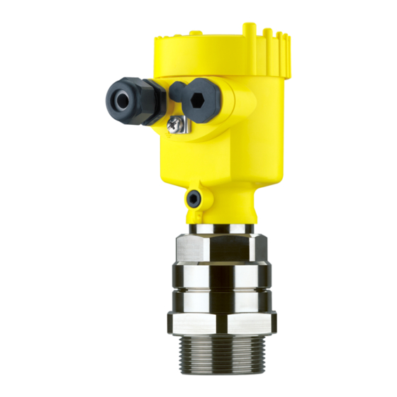
Article numbers, documentation With the serial number, you can access the delivery data of the instrument via www.vega.com, "VEGA Tools" and "serial number search". In addition to the type label outside, you can also find the serial number on the inside of the instrument. - Page 8 The VEGAMIP 61 consists of the following components. Fig. 1: VEGAMIP 61 with plastic housing Emitting unit VEGAMIP T61 Receiving unit VEGAMIP R61 with control electronics Housing cover Housing with control electronics Process fitting...
-
Page 9: Packaging, Transport And Storage
Nonobservance of these instructions can cause damage to the device. Transport inspection The delivery must be checked for completeness and possible transit damage immediately at receipt. Ascertained transit damage or concealed defects must be appropriately dealt with. VEGAMIP R61 • - Relay... -
Page 10: Accessories And Replacement Parts
You will find additional information in the supplementary instructions manual "Flanges according to DIN-EN-ASME-JIS" (Document-ID 31088). Electronics module The electronics module VEGAMIP R61 is a replacement part for microwave barriers of VEGAMIP series 60. You will find additional information in the following operating instructions manual: "Electronics module VEGAMIP R61 (receiving unit)"... - Page 11 With high process temperatures exceeding 80 °C, you have to use a Mounting adapter mounting adapter for the emitting and receiving unit. The mounting adapter can be only used with the encapsulated horn antenna with PTFE cover. Fig. 3: VEGAMIP 61 with high temperature mounting adapter VEGAMIP R61 • - Relay...
-
Page 12: Mounting
(e.g. through cleaning processes) or on cooled or heated vessels. 4.2 Mounting instructions If possible, install VEGAMIP 61 in a position where a high signal Switching point damping by the medium is expected. VEGAMIP R61 • - Relay... - Page 13 In metal vessels, you have to mount VEGAMIP 61 on flanges or Metal vessels threaded sockets. It is also possible to measure through a window. In general, all products such as glass, ceramic and plastic are suitable as window material. VEGAMIP R61 • - Relay...
- Page 14 Fig. 7: Installation in pipelines Min. distance 100 mm (3.94 in) Mount the threaded version of VEGAMIP 61 in the following way: Threaded version VEGAMIP R61 • - Relay...
- Page 15 Hence, no counter nut is necessary for these versions. Buildup Avoid long sockets in which the medium can remain and if possible, mount VEGAMIP 61 front-flush. This applies mainly if buildup and dust are expected. VEGAMIP R61 • - Relay...
- Page 16 For an optimum switching signal, the two sensors must be adapted to each other. The accuracy must be in a range of ±5°. General rule: the bigger the antenna and the better it focusses, the more precise the orientation has to be. VEGAMIP R61 • - Relay...
- Page 17 If several instrument pairs are installed in a vessel, the instrument pairs can be coded by different polarisation positions to avoid that they influence one another. Fig. 11: Orientation according to the polarisation direction Polarisation marking on top Polarisation marking lateral VEGAMIP R61 • - Relay...
- Page 18 With instrument versions with detachable horn antenna, the antenna extension can be retrofitted. Fig. 12: Possibilities for signal deflection Metal plate for signal deflection of the microwave signal Bent antenna extension VEGAMIP R61 • - Relay...
-
Page 19: Connecting To Power Supply
Unscrew the housing cover Loosen compression nut of the cable entry Remove approx. 10 cm (4 in) of the cable mantle, strip approx. 1 cm (0.4 in) of insulation from the ends of the individual wires VEGAMIP R61 • - Relay... - Page 20 The terminal block is pluggable and can be removed from the electronics. For this purpose, lift the terminal block with a small screwdriver and pull it out. When inserting the terminal block again, you should hear it snap in. VEGAMIP R61 • - Relay...
-
Page 21: Wiring Plan, Single Chamber Housing
(safe condition). Information: The relays are always shown in non-operative condition. Fig. 14: Wiring plan receiving unit - VEGAMIP 61 (receiver) Relay output Relay output Voltage supply VEGAMIP R61 • - Relay... -
Page 22: Setup
The signal lamp signals the switching condition of the switching output. Control lamp (green) for indication of the instrument function (4) The green signal lamp (on) shows the operating state of the instrument as soon as voltage supply is connected correctly. VEGAMIP R61 • - Relay... -
Page 23: Adjustment
Level Switching status Signal lamp - Re- lay (yellow) Mode max. Overflow protection (6) (7) Relay energized Mode max. Overflow protection (6) (7) Relay deenergized Mode min. Dry run protection (6) (7) Relay energized VEGAMIP R61 • - Relay... - Page 24 The LED indication strip always shows a small section of the actual measuring range. Pressing the "<--" key makes the sensor more sensitive. Pressing the "-->" key makes the sensor less sensitive. VEGAMIP R61 • - Relay...
- Page 25 In this case, the VEGAMIP 61 switches only with a relatively high signal damping by the medium. Probable buildup does not influence the measurement. VEGAMIP R61 • - Relay...
- Page 26 Hence, the VEGAMIP 61 switches very sensitive, even with relatively low covering by the product. 4 5 6 7 8 3 4 5 6 7 8 Fig. 31: LED indication strip - Setting for products with low signal damping VEGAMIP R61 • - Relay...
- Page 27 If possible, you can simulate a filling between emitting and receiving unit by using the hand or a metal sheet and check if the switching point is adjusted correctly. If the relay control lamp changes the switching condition, then the switching function is correct. VEGAMIP R61 • - Relay...
-
Page 28: Maintenance And Fault Rectification
Signal lamp lights red Operating voltage too low Check operating voltage Electronics module has Exchange the instrument or send it in for repair detected an internal failure Instrument switches de- Check switching delay Adjust switching delay correctly layed VEGAMIP R61 • - Relay... -
Page 29: Exchange The Electronics
"Set up" must be carried out again, if necessary. 24 hour service hotline However, should these measures not be successful, call the VEGA service hotline in urgent cases under the phone no. +49 1805 858550. The hotline is available to you 7 days a week round-the-clock. Since we offer this service world-wide, the support is only available in the... -
Page 30: Dismounting
Correct disposal avoids negative effects to persons and environment and ensures recycling of useful raw materials. Materials: see chapter "Technical data" If you have no possibility to dispose of the old instrument professionally, please contact us concerning return and disposal. VEGAMIP R61 • - Relay... -
Page 31: Supplement
0.1 … 100 m (0.33 … 328 ft) Measuring range Angle of aperture of the antenna 3 dB 20 ° Encapsulated horn antenna (G1½ A) 10 ° Plastic encapsulated antenna with PP cover Output variable Relay output, 2 floating spdts Output VEGAMIP R61 • - Relay... - Page 32 Cable entry/plug (dependent on the version) 1 x cable entry M20 x 1.5 (cable: ø 5 … 9 mm), Single chamber housing 1 x blind stopper M20 x 1.5; attached 1 x cable entry M20 x 1.5 VEGAMIP R61 • - Relay...
- Page 33 Depending on the version, instruments with approvals can have different technical data. For these instruments, the corresponding approval documents have to be taken into account. These are part of the delivery or can be downloaded under www.vega.com via "VEGA Tools" and "serial number search" as well as via "Downloads" and "Approvals".
-
Page 34: Dimensions
SW 60 mm (1.42") 1½ NPT G1½ A Fig. 34: VEGAMIP 61 Threaded version - encapsulated horn antenna with PTFE cover - G1½ A Threaded version - encapsulated horn antenna with PTFE cover - 1½ NPT VEGAMIP R61 • - Relay... - Page 35 VEGAMIP 61 - Mounting adapter (-40 … +450 °C) 24 mm (0.95") 61 mm (2.4") Fig. 36: Mounting adapter with ceramic cover for VEGAMIP 61 - threaded version with PTFE cover 150 mm (5.9 in) or 300 mm (11.8 in) VEGAMIP R61 • - Relay...
- Page 36 Les lignes de produits VEGA sont globalement protégées par des droits de propriété intellectuelle. Pour plus d'informations, on pourra se référer au site http://www.vega.com VEGA lineas de productos están protegidas por los derechos en el campo de la propiedad industrial. Para mayor información revise la pagina web http://www.vega.com Линии...
- Page 37 Mounting adapter 11 Orientation of the sensor 16 Pipelines 14 Potential equalisation 19 Receiving unit 8, 21-22 Sensitivity adjustment 24 Serial number 7 Service hotline 29 Shielding 19 Simulation 27 Switching delay 27 Switching point 12 VEGAMIP R61 • - Relay...
- Page 38 Index VEGAMIP R61 • - Relay...
- Page 39 Index VEGAMIP R61 • - Relay...
- Page 40 All statements concerning scope of delivery, application, practical use and operating conditions of the sensors and processing systems correspond to the information avail- able at the time of printing. © VEGA Grieshaber KG, Schiltach/Germany 2010 35786-EN-100531 Subject to change without prior notice...
Need help?
Do you have a question about the VEGAMIP R61 and is the answer not in the manual?
Questions and answers