Vega MINITRAC 31 Installation & Maintenance Instructions Manual
4...20 ma/hart - four-wire
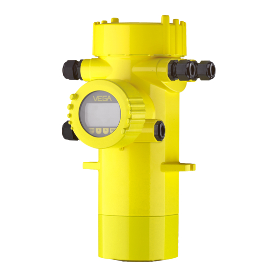
radiation-based sensor for density measurement
Hide thumbs
Also See for MINITRAC 31:
- Quick setup manual (28 pages) ,
- Operating instructions manual (80 pages) ,
- Operating instructions manual (92 pages)
Table of Contents
Advertisement
Installation & Maintenance Instructions
MINITRAC 31
4 ... 20 mA/HART - four-wire
Radiation-based sensor for density measurement
Reading Office
Aberdeen Office
Cutbush Park, Danehill, Lower Earley,
Unit 6 Airside Business Park, Kirkhill Industrial Estate,
Reading, Berkshire. RG6 4UT. UK.
Dyce, Aberdeen. AB21 0GT. UK.
Tel: +44 (0)118 9311188
Tel: +44 (0)1224 725999
Email: info@able.co.uk
Email: ab@able.co.uk
Internet: www.able.co.uk
e-procurement: www.247able.com
Registered in England No: 01851002
VAT No: GB 417 2481 61
Advertisement
Table of Contents

Related Manuals for Vega MINITRAC 31


Summary of Contents for Vega MINITRAC 31
- Page 1 Installation & Maintenance Instructions MINITRAC 31 4 … 20 mA/HART - four-wire Radiation-based sensor for density measurement Reading Office Aberdeen Office Cutbush Park, Danehill, Lower Earley, Unit 6 Airside Business Park, Kirkhill Industrial Estate, Internet: www.able.co.uk Reading, Berkshire. RG6 4UT. UK.
-
Page 2: Table Of Contents
Saving the parameter adjustment data ................61 Set up with other systems DD adjustment programs ....................62 Field Communicator 375, 475 ..................62 Diagnostics and service Maintenance ........................63 Status messages ......................63 Rectify faults ........................67 MINITRAC 31 • 4 … 20 mA/HART - four-wire... - Page 3 11.2 Dimensions ........................77 Safety instructions for Ex areas Please note the Ex-specific safety information for installation and op- eration in Ex areas. These safety instructions are part of the operating instructions manual and come with the Ex-approved instruments. Editing status: 2013-04-29 MINITRAC 31 • 4 … 20 mA/HART - four-wire...
-
Page 4: About This Document
This arrow indicates a single action. Sequence Numbers set in front indicate successive steps in a procedure. Battery disposal This symbol indicates special information about the disposal of bat- teries and accumulators. MINITRAC 31 • 4 … 20 mA/HART - four-wire... -
Page 5: For Your Safety
During work on and with the device the required personal protective equipment must always be worn. Appropriate use The MINITRAC 31 is a sensor for density measurement and level detection. You can find detailed information on the application range in chapter "Product description". Operational reliability is ensured only if the instrument is properly used according to the specifications in the operating instructions manual as well as possible supplementary instructions. -
Page 6: Ce Conformity
That is why we have introduced an environment management system with the goal of continuously improving company environmental pro- tection. The environment management system is certified according to DIN EN ISO 14001. Please help us fulfill this obligation by observing the environmental instructions in this manual: • Chapter "Packaging, transport and storage" • Chapter "Disposal" MINITRAC 31 • 4 … 20 mA/HART - four-wire... -
Page 7: Product Description
Enter the serial number manually into the App Scope of this operating This operating instructions manual applies to the following instrument instructions manual versions: • Hardware from 1.0.4 • Software from 1.4.2 • Modification status, electronics as of -01 MINITRAC 31 • 4 … 20 mA/HART - four-wire... -
Page 8: Principle Of Operation
The instrument can be used for many different measuring tasks. Apart from the main applications such as density measurement and level detection, the MINITRAC 31 can also detect residues and the mass flow rate in conjunction with a flow meter. MINITRAC 31 • 4 … 20 mA/HART - four-wire... - Page 9 The measuring principle has proven to be very reliable in conjunction with extreme process conditions because it measures contactlessly from outside through the tube wall. The measuring system ensures MINITRAC 31 • 4 … 20 mA/HART - four-wire...
-
Page 10: Packaging, Transport And Storage
PLICSCOM" (Document-ID 27835). VEGACONNECT The interface adapter VEGACONNECT enables the connection of communication-capable instruments to the USB interface of a PC. For parameter adjustment of these instruments, an adjustment software such as PACTware with VEGA-DTM is required. You can find further information in the operating instructions "Interface adapter VEGACONNECT" (Document-ID 32628). MINITRAC 31 • 4 … 20 mA/HART - four-wire... -
Page 11: Corresponding Source Container
When handling a radioactive source, unnecessary radiation exposure radiation protection must be avoided. An unavoidable radiation exposure must be kept as low as possible. Take note of the following three important measures: MINITRAC 31 • 4 … 20 mA/HART - four-wire... - Page 12 (in Ger- many, for example, the radiation protection ordinance). We are at your disposal for further information concerning radiation protection and regulations in other countries. MINITRAC 31 • 4 … 20 mA/HART - four-wire...
-
Page 13: Mounting
Prior to setup you have to replace these protective caps with ap- proved cable glands or close the openings with suitable blind plugs. The suitable cable glands and blind plugs come with the instrument. MINITRAC 31 • 4 … 20 mA/HART - four-wire... -
Page 14: Mounting Instructions
You can mount the MINITRAC 31 in any position. If you have ordered your instrument with a lead cover as a protection against ambient radiation (optionally), the the sensor is shielded laterally against X-ray radiation. - Page 15 Extension of the radiated length (L) by adding a tube angle piece as meas- uring distance Integrated lead cover as protection against ambient radiation - the instru- ment is hence shielded laterally MINITRAC 31 • 4 … 20 mA/HART - four-wire...
- Page 16 Make sure that there are no struts or reinforcements at this position in the vessel. Direct the exit beam of the source container exactly towards the measuring range of MINITRAC 31. MINITRAC 31 • 4 … 20 mA/HART - four-wire...
- Page 17 Mounting horizontally, at right angles to container Level measurement - Residue detection The MINITRAC 31 can be used for residue detection, e.g. in storage tanks for high-cost liquids. For this purpose, the instrument must be mounted at the lowest point of the vessel.
- Page 18 The water cooling must also be included in the calculations for the measuring point. Contact our specialists regarding the dimensioning of the water cooling. MINITRAC 31 • 4 … 20 mA/HART - four-wire...
-
Page 19: Connecting To Power Supply
In the sensor, the screen must be connected directly to the internal ground terminal. The ground terminal on the outside of the housing must be connected to the potential equalisa- tion (low impedance). MINITRAC 31 • 4 … 20 mA/HART - four-wire... - Page 20 3. Remove approx. 10 cm (4 in) of the cable mantle, strip approx. 1 cm (0.4 in) of insulation from the ends of the individual wires 4. Insert the cable into the sensor through the cable entry MINITRAC 31 • 4 … 20 mA/HART - four-wire...
- Page 21 10. Screw the housing cover back on The electrical connection is hence finished. Information: The terminal blocks are pluggable and can be detached from the electronics. For this purpose loosen the two lateral locking levers of MINITRAC 31 • 4 … 20 mA/HART - four-wire...
-
Page 22: Connection - Density, Mass Flow Rate Measurement
Fig. 11: Adjustment and connection compartment with non-Ex instruments and instruments with non-intrinsically safe current output Terminals for the external display and adjustment unit Contact pins for the display and adjustment module or interface adapter MGC = Multi Gauge Communication MINITRAC 31 • 4 … 20 mA/HART - four-wire... - Page 23 Ex-d approval) Contact pins for the display and adjustment module or interface adapter Terminals for the external display and adjustment unit Ground terminal MGC = Multi Gauge Communication MINITRAC 31 • 4 … 20 mA/HART - four-wire...
-
Page 24: Connection - Level Detection
Contact pins for the display and adjustment module or interface adapter Instruments with intrinsically safe current output You can find detailed information on the explosion-protected versions (Ex-ia, Ex-d) in the Ex-specific safety instructions. These safety instructions are part of the scope of delivery and come with the Ex- approved instruments. MGC = Multi Gauge Communication MINITRAC 31 • 4 … 20 mA/HART - four-wire... - Page 25 (not with versions with Ex-d approval) Contact pins for the display and adjustment module or interface adapter Terminals for the external display and adjustment unit Ground terminal MGC = Multi Gauge Communication MINITRAC 31 • 4 … 20 mA/HART - four-wire...
-
Page 26: Set Up With The Display And Adjustment Module
The display and adjustment module is powered by the sensor, an ad- ditional connection is not necessary. Fig. 18: Insert display and adjustment module Note: If you intend to retrofit the instrument with a display and adjustment module for continuous measured value indication, a higher cover with an inspection glass is required. MINITRAC 31 • 4 … 20 mA/HART - four-wire... -
Page 27: Adjustment System
[OK] will not be saved. Parameter adjustment - Level measurement Through the parameter adjustment the instrument is adapted to the application conditions. The parameter adjustment is carried out via an adjustment menu. MINITRAC 31 • 4 … 20 mA/HART - four-wire... - Page 28 This parameter is described in the operating instructions manual "Display and adjustment module". Setup/Isotope In this menu item you can adjust the MINITRAC 31 to the integrated isotope in the source container. MINITRAC 31 • 4 … 20 mA/HART - four-wire...
- Page 29 With this menu item the natural background radiation can be faded out. For this purpose, the MINITRAC 31 measures the natural background radiation and sets the pulse rate to zero. In the future, the pulse rate from this background radiation will be automatically deducted from the total pulse rate. This means: only the component of the pulse rate originating from the source will be displayed.
- Page 30 The relay outputs of the sensor react accordingly. You can choose "no" reference value. In this case, the relay output operates as fail safe relay. Caution: Independent of the selected reference value, the relay will deenergize in case of failure. MINITRAC 31 • 4 … 20 mA/HART - four-wire...
- Page 31 Reference value - Relay None Block operation Released Display Language Selected language Displayed value Pulse rate Display unit ct/s Additional settings Temperature unit °C Linearization curve Empty HART mode Standard Address 0 MINITRAC 31 • 4 … 20 mA/HART - four-wire...
-
Page 32: Parameter Adjustment - Density Measurement
Info: Instrument name, hardware and software version, date of manu- facture, instrument features Proceeding Check if the correct language is already set for the display. If not, you can change the language in the menu item "Display/Language". MINITRAC 31 • 4 … 20 mA/HART - four-wire... - Page 33 This parameter is described in the operating instructions manual "Display and adjustment module". Setup/Isotope In this menu item you can adjust the MINITRAC 31 to the integrated isotope in the source container. For this purpose, check which isotope is integrated in the source container. You can find this information on the type label of the source...
- Page 34 Make sure that some products have a self-radiation. This is for ex- ample the case with oil or potash salt lye. Therefore the tube must be filled to determine the background radiation. For this purpose, the MINITRAC 31 measures the natural background radiation and sets the pulse rate to zero. In the future, the pulse rate from this background radiation will be automatically deducted from the total pulse rate.
- Page 35 (L) instead of the tube inside diameter. Enter also here the radiated length without the wall thickness of the tube. Fig. 20: With inclined mounting, the radiated length of the tube is applicable MINITRAC 31 • 4 … 20 mA/HART - four-wire...
- Page 36 • Prerequisites: The radiation is switched on - source container is set to "On" The tube is completely filled. Possible gas bubbles or air inclusions can influence the measurement. The MINITRAC 31 sorts the points automatically according to their density. Select "Show table" to display and edit the linearization points. Select "Linearization - New" to enter the first point. Select "Determine count rate" to enter the first point. The determination of the actual count rate lasts 2 minutes. After the count rate was determined, you can accept the value.
- Page 37 If you cannot change the medium during the adjustment process, it is possible to carry out the linearization with only one point. However, you should enter further linearization points later, if possible. • Show diagram This menu item is only available if a linearization was already carried out. • Show table In this menu item you can show the individual value pairs of the linearization. • Linearization - Delete MINITRAC 31 • 4 … 20 mA/HART - four-wire...
- Page 38 With the setting "Automatic", the instrument itself calculates a suitable damping on the basis of the adjustment and the measured value changes. This setting is particularly suitable for application where fast and slow level changes occur. MINITRAC 31 • 4 … 20 mA/HART - four-wire...
- Page 39 This fault message is only outputted for the period of the increased X-ray radiation. Then the fault message is automatically reset. In this menu item you can determine the behaviour of the sensor when external radiation sources appear. MINITRAC 31 • 4 … 20 mA/HART - four-wire...
- Page 40 This menu item is described in the operating instructions manual "Display and adjustment module". Display Display/Language With this parameter you can change the display language. This parameter is described in the operating instructions manual "Display and adjustment module". MINITRAC 31 • 4 … 20 mA/HART - four-wire...
- Page 41 In this menu item you can simulate measured values via the current output. This allows the signal path to be tested, e.g. via downstream indicating instruments or the input card of the control system. You can simulate different values: Pulse rate of the sensor MINITRAC 31 • 4 … 20 mA/HART - four-wire...
- Page 42 The following reset functions are available: Basic adjustments: Resetting of the parameter adjustmetns to default values at the time of shipment. Order-specific settings will be deleted. Default settings: Resetting of the parameter adjustment like under "Basic adjustment". In addition, special parameters will be reset to default values. Order-specific settings will not be deleted. MINITRAC 31 • 4 … 20 mA/HART - four-wire...
- Page 43 With this function you can select the mode. HART mode The sensor offers the HART modes standard and multidrop. The mode 'Standard' with the fixed address 0 (factory setting) means output of the measured value as 4 … 20 mA signal. This parameter is described in the operating instructions manual "Display and adjustment module". MINITRAC 31 • 4 … 20 mA/HART - four-wire...
-
Page 44: Parameter Adjustment - Level Detection
Display: Settings, for example language, measured value display Diagnosis: Information, for example, of device status, peak value, simulation Additional adjustments: Instrument unit, reset, date/time, copying function MINITRAC 31 • 4 … 20 mA/HART - four-wire... - Page 45 This parameter is described in the operating instructions manual "Display and adjustment module". Setup/Isotope In this menu item you can adjust the MINITRAC 31 to the integrated isotope in the source container. For this purpose, check which isotope is integrated in the source container. You can find this information on the type label of the source...
- Page 46 This menu item appears only if you have selected "Single point Setup/Adjustment uncovered (single point adjustment" as adjustment mode (Setup/Adjustment mode). adjustment) In this menu item you determine the point at which the MINITRAC 31 should switch in uncovered status. MINITRAC 31 • 4 … 20 mA/HART - four-wire...
- Page 47 Empty the vessel until the sensor is uncovered. For this enter the requested pulse rate manually or let the rate be determined by MINITRAC 31. Automatic determination of the pulse rate should be given preference. The pulse rate is entered in ct/s. This is the number of counts per second, i.e.
- Page 48 You thus get the min. pulse rate (ct/s) for the adjustment covered. Enter the requested pulse rate manually or let the rate be determined by MINITRAC 31. Automatic determination of the pulse rate should be given preference. You can enter the adjustment point (ct/s) manually.
- Page 49 "Display and adjustment module". Display/Displayed value With this parameter you can change the indication of the display. You can select if the display should show the actual pulse rate of the electronics temperature. MINITRAC 31 • 4 … 20 mA/HART - four-wire...
- Page 50 In this menu item you can simulate measured values via the current output. This allows the signal path to be tested, e.g. via downstream indicating instruments or the input card of the control system. You can simulate different values: Pulse rate of the sensor MINITRAC 31 • 4 … 20 mA/HART - four-wire...
- Page 51 When a reset is carried out, all settings (with only a few exceptions) - Reset are reset. The exceptions are: PIN, language, SIL and HART mode. The following reset functions are available: Basic adjustments: Resetting of the parameter adjustmetns to default values at the time of shipment. Order-specific settings will be deleted. MINITRAC 31 • 4 … 20 mA/HART - four-wire...
- Page 52 With this function you can select the mode. Additional adjustments/ HART mode The sensor offers the HART modes standard and multidrop. If the measured value is outputted via the 4 … 20 mA output, you must not switch over to HART Multidrop. MINITRAC 31 • 4 … 20 mA/HART - four-wire...
-
Page 53: Parameter Adjustment - X-Ray Alarm
Set the address setting (MGC) on the Master instrument to "0 - 0". You have to enter the address of the Slave instrument in the list of the Master instrument. This function is not possible in the display and MINITRAC 31 • 4 … 20 mA/HART - four-wire... - Page 54 This parameter is described in the operating instructions manual "Display and adjustment module". Setup/Isotope In this menu item you can adjust the MINITRAC 31 to the integrated isotope in the source container. For this purpose, check which isotope is integrated in the source container. You can find this information on the type label of the source...
-
Page 55: Parameter Adjustment/Real Value Correction
Setup/Outputs When the output is activated, the instrument remains in its function as a Slave, but the 4 … 20 mA output of the MINITRAC 31 can be also used als single instrument. The instrument has again the complete functionality when the output is active again. - Page 56 In this menu item you can assign an unambiguous name to the sen- loop name sor or the measurement loop. This parameter is described in the operating instructions manual "Display and adjustment module". MINITRAC 31 • 4 … 20 mA/HART - four-wire...
-
Page 57: Saving The Parameter Adjustment Data
6 Set up with the display and adjustment module In this menu item you can adjust the MINITRAC 31 to the integrated Setup/Isotope isotope in the source container. For this purpose, check which isotope is integrated in the source container. You can find this information on the type label of the source container. - Page 58 If it is necessary to exchange a sensor, the display and adjustment module is inserted into the replacement instrument and the data are likewise written into the sensor via the menu item "Copy sensor data". MINITRAC 31 • 4 … 20 mA/HART - four-wire...
-
Page 59: Setup With Pactware
Fig. 22: Connecting the PC via HART to the signal cable MINITRAC 31 2 HART resistance 250 Ω (optional depending on processing) Connection cable with 2 mm pins and terminals Processing system/PLC/Voltage supply Voltage supply Necessary components: • MINITRAC 31 • PC with PACTware and suitable VEGA DTM MINITRAC 31 • 4 … 20 mA/HART - four-wire... -
Page 60: Parameter Adjustment With Pactware
"DTM Collection/PACTware" attached to each DTM Collection and which can also be downloaded from the Internet. Detailed descrip- tions are available in the online help of PACTware and the DTMs. MINITRAC 31 • 4 … 20 mA/HART - four-wire... -
Page 61: Saving The Parameter Adjustment Data
The standard version is available as a download under www.vega. com/downloads and "Software". The full version is available on CD from the agency serving you. -
Page 62: Set Up With Other Systems
DD adjustment programs such as, for example, AMS™ and PDM. The files can be downloaded at www.vega.com/downloads under "Software". Field Communicator 375, 475 Device descriptions for the instrument are available as EDD for pa- rameter adjustment with the Field Communicator 375 or 475. MINITRAC 31 • 4 … 20 mA/HART - four-wire... -
Page 63: Diagnostics And Service
PACTware/DTM or EDD. Out of specification: The measured value is unstable because the instrument specification is exceeded (e.g. electronics temperature). This status message is inactive by default. It can be activated by the user via PACTware/DTM or EDD. Maintenance: Due to external influences, the instrument function is limited. The measurement is affected, but the measured value is MINITRAC 31 • 4 … 20 mA/HART - four-wire... - Page 64 – Carry out a reset ment communication – Exchanging the electronics EPROM data error F036 – Error during software – Repeat software update update – Exchanging the electronics Faulty pro- gram memory MINITRAC 31 • 4 … 20 mA/HART - four-wire...
- Page 65 – Call our service Communica- tion error F114 – Discharge accumulator – Readjust real time clock Error real time clock F120 – Faulty or missing instrument – Carrying out adjustment adjustment Filter time error MINITRAC 31 • 4 … 20 mA/HART - four-wire...
- Page 66 "Out of specification" and provides information on causes as well as corrective measures. Code Cause Rectification Text mes- sage S017 – Accuracy outside the – Correct adjustment data specification Accuracy outside the specification MINITRAC 31 • 4 … 20 mA/HART - four-wire...
-
Page 67: Rectify Faults
"Wiring plan" Voltage supply Check cables for breaks; repair if nec- missing essary Operating voltage Check, adapt if necessary too low or load re- sistance too high MINITRAC 31 • 4 … 20 mA/HART - four-wire... -
Page 68: Exchanging The Electronics Module
In Ex applications only one instrument and one electronics module with respective Ex approval may be used. If there is no electronics module available on site, the electronics module can be ordered through the agency serving you. The electron- MINITRAC 31 • 4 … 20 mA/HART - four-wire... -
Page 69: Software Update
If a sensor repair is necessary, please proceed as follows: • Print and fill out one form per instrument • Clean the instrument and pack it damage-proof • Attach the completed form and, if need be, also a safety data sheet outside on the packaging MINITRAC 31 • 4 … 20 mA/HART - four-wire... - Page 70 9 Diagnostics and service • Please ask the agency serving you for the address of your return shipment. You can find the competent agency on our website www.vega.com. MINITRAC 31 • 4 … 20 mA/HART - four-wire...
-
Page 71: Dismounting
Pass the instrument directly on to a spe- cialised recycling company and do not use the municipal collecting points. These may be used only for privately used products according to the WEEE directive. MINITRAC 31 • 4 … 20 mA/HART - four-wire... -
Page 72: Supplement
The measured variable is the intensity of the gamma ra- diation of an isotope. If the radiation intensity decreases, e.g. due to increasing product density, the measured value of MINITRAC 31 changes in proportion to the density. Analogue input Ʋ Input type 4 …... - Page 73 Starting current ≤ 3.6 mA Load Ʋ 4 … 20 mA/HART - active < 500 Ω Ʋ 4 … 20 mA/HART - intrinsically safe < 300 Ω Damping (63 % of the input variable) Automatically HART output values MINITRAC 31 • 4 … 20 mA/HART - four-wire...
- Page 74 Damping (63 % of the input variable) 1 … 1200 s, adjustable HART output values Ʋ PV (Primary Value) Switching status Ʋ SV (Secondary Value) Electronics temperature Relay output Output Relay output (SPDT), floating spdt Switching voltage Ʋ Min. 10 mV Ʋ Max. 253 V AC, 253 V DC MINITRAC 31 • 4 … 20 mA/HART - four-wire...
- Page 75 EN 61326 Characteristics and performance data Step response time ≤ 5 s (with damping 1 s) Time span after a sudden measuring distance change by max. 0.5 m in liquid applications, max 2 m with bulk solids applications, until the output signal has taken for the first time 90 % of the final value (IEC 61298-2). MINITRAC 31 • 4 … 20 mA/HART - four-wire...
- Page 76 Material Ʋ Housing Ʋ Inspection window Polyester foil Integrated clock Date format Day.Month.Year Time format 12 h/24 h Time zone Ex factory Tested according to the guidelines of German Lloyd, GL directive 2. MINITRAC 31 • 4 … 20 mA/HART - four-wire...
-
Page 77: Dimensions
Approvals Instruments with approvals can have different technical data depending on the version. For that reason the associated approval documents of these instruments must be carefully noted. They are part of the delivery or can be downloaded under www.vega.com and "VEGA Tools" as well as under "Downloads" and "Approvals". 11.2 Dimensions The following dimensional drawings represent only an extract of all possible versions. - Page 78 ½ NPT (4.69") 169 mm (6.65") 116,5 mm 175 mm (4.59") (6.89") 90 mm 100 mm (3.54") (3.94") 143,5 mm (5.65") Fig. 25: Aluminium housing or stainless steel housing - Precision casting MINITRAC 31 • 4 … 20 mA/HART - four-wire...
- Page 79 11 Supplement MINITRAC 31 Fig. 26: MINITRAC 31 Measuring range MINITRAC 31 • 4 … 20 mA/HART - four-wire...
- Page 80 Les lignes de produits VEGA sont globalement protégées par des droits de propriété intellec- tuelle. Pour plus d'informations, on pourra se référer au site www.vega.com. VEGA lineas de productos están protegidas por los derechos en el campo de la propiedad indus- trial. Para mayor información revise la pagina web www.vega.com.
- Page 81 Radiation source 28, 33, 45, 54, 57 Real value correction 39, 55 Relay 30, 40, 49 Grounding 19 Repair 69 Replacement parts – Electronics module 11 Handling permit 11 Reset 42, 51 MINITRAC 31 • 4 … 20 mA/HART - four-wire...
- Page 82 Units 29, 34 Shielding 19 Simulation 41, 50 Source container 11 Voltage supply 19, 77 Status messages 63 Storage 10 Water cooling 18 Time 42, 51 Type plate 7 X-ray alarm 30, 39, 53 MINITRAC 31 • 4 … 20 mA/HART - four-wire...
- Page 83 Notes MINITRAC 31 • 4 … 20 mA/HART - four-wire...
- Page 84 Subject to change without prior notice © VEGA Grieshaber KG, Schiltach/Germany 2013 VEGA Grieshaber KG Phone +49 7836 50-0 Am Hohenstein 113...
Need help?
Do you have a question about the MINITRAC 31 and is the answer not in the manual?
Questions and answers