MES SQA-V Gold Service Manual
Hide thumbs
Also See for SQA-V Gold:
- User manual (71 pages) ,
- Service manual (44 pages) ,
- Quick start manual (3 pages)

Related Manuals for MES SQA-V Gold


Summary of Contents for MES SQA-V Gold
- Page 1 SQA-V S e r v i c e M a n u a l V e r s i o n 2 . 4 8 / 2 . 4 9 / 2 . 6 0 Catalog #7501 Rev: April 2014...
-
Page 2: Table Of Contents
SQA-V Service Manual 24_Apr_2014 SECTION I: Introduction Table of Automated Test Results Contents Technology Automated System Visualization System SECTION II: System Specifications Sperm Quality Analyzer –SQA-V Version 2.48/2.49 SECTION III: System Overview Front Panel Key Pad Rear Panel Side Panel The Chassis Assembly The Cover Assembly Schematic of the SQA-V Motherboard... - Page 3 SQA-V Service Manual 24_Apr_2014 SECTION IX: Error Messages Stabilization Failed Self-Test Failed Electronic Noise Concentration out of Range Control Testing Sample size out of range I-Button warning screen Communication Error SECTION X: Appendix Cleaning the SQA-V I-Button Loading Instructions Replacing the Processor Power Supply Troubleshooting Flowchart...
-
Page 4: Section I: Introduction
SQA-V Service Manual 24_Apr_2014 SECTION I: Introduction The SQA-V is a high performance analytical medical device that combines state-of- the-art technology in electro-optics, computer algorithms and video microscopy. The system performs a precise, 75-second semen analysis. The SQA-V runs a self-test and auto-calibration on start-up and also runs external quality controls. -
Page 5: Visualization System
SQA-V Service Manual 24_Apr_2014 Step 1: The capillary is inserted into the measurement compartment. Step 2: Sample concentration is evaluated in the "tall" 10 mm chamber of the capillary by measuring the amount of optical absorption of light as a beam traverses the seminal fluid. -
Page 6: Section Ii: System Specifications
SQA-V Service Manual 24_Apr_2014 SECTION II: System Specifications Sperm Quality Dimensions: 40 Height x Width 30 x 15 - 25 cm Depth Analyzer Weight: 4.5 kg AC power supply: 100 to 250 VAC, 50/60 Hz, 24W Fuse rating: 2A 250V Power stability requirements: Voltage fluctuations ±... - Page 7 SQA-V Service Manual 24_Apr_2014 Specimen Testing Supplies Measurement capillary: Disposable, plastic, positive displacement testing capillary. (Testing depth of capillary section: 300-micron; Cuvette section: 10 mm). Standard laboratory slide: 20 micron depth, 22 x 22 mm cover-slip. Operating System ...
- Page 8 SQA-V Service Manual 24_Apr_2014 NOTE: Variations in ambient temperature may impact the accuracy of test results because of the effect of temperature on human semen. System is fully operational at up to 80% humidity and 26°C. Maintenance Schedule ...
-
Page 9: Key Pad
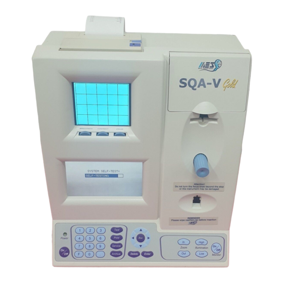
SQA-V Service Manual 24_Apr_2014 SECTION III: System Overview SQA-V Visualization System compartment: Printer and paper Accommodates both a Prpaper slide and the SQA-V testing capillary Video display and controls Focus knob Operational display NOTE: I-Button TEST button of Automated the SQA-V Measurement keypad is only compartment... -
Page 10: The Chassis Assembly
SQA-V Service Manual 24_Apr_2014 The Chassis Assembly The Cover Assembly Assemblies The chassis assembly includes both the The cover assembly includes the following: base and rear panel and contains the Operational Display following sub-assemblies: Video Keypad Main Board ... -
Page 11: Slide Adaptor
SQA-V Service Manual 24_Apr_2014 Slide Slide Adaptor Adaptor For use with a standard laboratory slide 76 x 25.6 mm and 22 x 22 mm cover-slip in the visualization compartment of the SQA-V to visually assess semen samples. Cleaning Kit Cleaning ... -
Page 12: Prior To Testing A Sample
SQA-V Service Manual 24_Apr_2014 Prior to testing a sample: Auto calibration verification: Reference values are read again. The concentration and motility parameters are measured (without a testing capillary). System noise: Measures the electronic noise level of the system to insure that noise thresholds are accurately defined in the system to ensure effective measurement of electronic signals. -
Page 13: Section Vii: Troubleshooting
PLEASE NOTE: supply cable from the back Only a qualified MES distributor who has been trained to perform technical of the device support is authorized to open the SQA-V. before opening the SQA-V. If the SQA-V is opened without authorization it may cause damage to the calibration AND will VOID THE WARRANTY. -
Page 14: Keypad
SQA-V Service Manual 24_Apr_2014 Disconnect the old Keypad Cable Keypad Keypad (Part # PCD-0201) ISSUE: The Keypad is not working Open the SQA-V Verify that the keypad cable is connected firmly to the Main board at J11 location (connector is not loose) ... -
Page 15: Power Supply Unit
SQA-V Service Manual 24_Apr_2014 Power Supply Unit – PSU Power Supply ISSUE: The main switch is ON but the power indicator does not light up and the fan is not working. Unit (PSU) Check the fuse in the fuse box located on the NOTES: rear panel of the SQA-V. - Page 16 SQA-V Service Manual 24_Apr_2014 4. Disconnect the two cables of the OLD PSU: Input connector- location P1 Output connector- location P2. This connector also includes the GROUND cable. Remove the old PSU ® 5. Assemble the black Formex cover to a new PSU 6.
-
Page 17: Power Inlet
SQA-V Service Manual 24_Apr_2014 Power Inlet (Part# AP-9081001) Power ISSUE: There is no power supplied to the PSU from the inlet. Inlet NOTEs: Open the SQA-V. Turn off the power supply Unscrew the power-inlet screws at the rear and disconnect panel of the device. -
Page 18: Operation Monitor (Lower Lcd Screen)
the main. If the problem persists, contact MES Customer Support. ISSUE #2- Blank Screen: There is no data displayed on the screen in spite of the fact that the SQA-V is ON, both power indicators are functioning and the fan is working. -
Page 19: Focus Knob
Replace the screen & reconnect the data and power cables. “blank screen technical In case the problem persists after replacing the LCD screen- contact MES Customer bulletin” in the Support. appendix section Data Cable Remove the four screws... -
Page 20: Video Screen
SQA-V Service Manual 24_Apr_2014 Video Screen (Part# LCD-0010) Video ISSUE: A problem in the video system occurs when there is a malfunction or maladjustment in one of these areas: Light source, CCD camera, Harness connection, Video display monitor To diagnose a video system problem, refer to the table below. Detailed instructions on how to repair the problem are presented after the table. - Page 21 (part # KHD-908-000852, instructions can be found in the appendix section of this manual) If the problem persists after replacing the cable- contact MES support) V-Sperm Image is better than the SQA-V: Adjust the brightness of the SQA-V ...
-
Page 22: Led Replacement
This type of problem can only occur in old systems- with The image on the SN lower than #1318 SQA-V is frozen In case of frozen or stuck image- please contact MES or stuck support services Visualization LED Replacement (Part #KHD-908-000849-03) ISSUE: No light seen from the light indicator, even after increasing the illumination by pressing the illumination button intermittently. - Page 23 SQA-V Service Manual 24_Apr_2014 The internal video cable is held in place by two plastic clips. While pressing the two plastic clips, push the internal video cable connector inside to release it. Gently lay the optical assembly on its rear section. ...
- Page 24 Do not start Remove the zoom DC motor by unscrewing the 2 screws (fig. 3 and 4). this procedure unless you have this track. Contact MES if you Remove the need a FALSE DC motor TRACK. Fig. 3 Fig. 4 ...
- Page 25 SQA-V Service Manual 24_Apr_2014 Slide the CCD tray over the FALSE TRACK, then remove the FALSE TRACK With the CCD tray attached to (enclosed within the FALSE TRACK. Seal the FALSE TRACK with the plastic cover to prevent the CCD tray from slipping out.
-
Page 26: Video Display Monitor
Remove the Video Display serial numbers, Connect the main cable of the new video please display. contact MES Using a Phillips screwdriver, secure the PCB of support the video display (four screws). services. Close the SQA-V. -
Page 27: Capillary Sensor Troubleshooting And Replacement
SQA-V Service Manual 24_Apr_2014 How to replace the Surge Protector: Turn off the SQA-V and disconnect the power cable from the rear panel. Remove the printer from the rear panel Remove the Printer Disconnect the printer cable and set the printer aside. - Page 28 SQA-V Service Manual 24_Apr_2014 How to replace the capillary sensor Turn off the power and open the SQA-V by unscrewing the screws from the rear panel using a #2 Philips screwdriver. Use a #2 Allen key, remove the four screws connecting the optical column to the front panel of the SQA-V.
-
Page 29: Optical Board To Led Cable Replacement
SQA-V Service Manual 24_Apr_2014 Optical Board to LED Cable - Replacement (Part # KHD-908-000689 REV 01) Optical Issue: When the noise level of the SQA-V (Parameter #17) is higher than 3, then the Board cables connecting the Optical Board to the LED Board need to be replaced. Cables ... -
Page 30: Visualization System Upgrade (Vsu)
SQA-V Service Manual 24_Apr_2014 Visualization System Upgrade – VSU (Part # V-M00571-00) Visualization System Issue: A VSU upgrade is available for purchase and can be easily installed on existing systems. The upgrade consists of THREE components: An improved Visualization LED Housing; A Upgrade new Focus Knob Assembly and an Improved Slide Adaptor. - Page 31 SQA-V Service Manual 24_Apr_2014 Stage 3: Replace the Focus knob See instructions in this manual.[Section #10] Stage 4: Close the SQA-V Re-connect the optical assembly to the front panel. Make sure to screw back all 4 screws. Close the back of the unit and fasten the 4 screws on the rear panel using a #2 Philips screwdriver.
-
Page 32: Section Ix: Error Messages
SQA-V Service Manual 24_Apr_2014 SECTION IX: Error Messages ERROR Messages 1. Stabilization Failed: Ensure there is no testing capillary in the measurement compartment. Remove the SQA-V from sources of electronic noise (cell phones, etc.). Clean measurement compartment (refer to Appendix). ... -
Page 33: Concentration Out Of Range
SQA-V Service Manual 24_Apr_2014 After cleaning: Press SERVICE > ESC. MAIN MENU will be displayed. Select TEST NEW PATIENT and re-run test. If this message is displayed again, reboot the device: Turn the system OFF then back ON at the main switch on the rear panel. ... -
Page 34: Sample Size Out Of Range
SQA-V Service Manual 24_Apr_2014 5. Sample size out of range If the sample size has been entered as > 50 ml the calculated parameters will not import to the V-Sperm software. 6. I-Button warning screen I-BUTTON NOT PROPERLY ACTIVATED ... -
Page 35: Section X: Appendix
SQA-V Service Manual 24_Apr_2014 Appendix: 1 SQA Cleaning Instructions SECTION X Appendix... -
Page 36: I-Button Loading Instructions
SQA-V Service Manual 24_Apr_2014 SECTION X Appendix 2: Loading I-Button Tests Appendix How to Load the I-button Applies to: ALL SQA-V (V, Vb, Ve, Vp and Vt) with new I-button clip hardware Issue date: July 31, 2014 Instructions: Procedure for LOADING THE I-BUTTON: 1. - Page 37 SQA-V Service Manual 24_Apr_2014 5. A progress bar can now be seen on V- Sperm. The button must remain inside the port as described above during the ENTIRE process of loading the tests until you receive the message: Button Tests successfully updated (see Fig.
-
Page 38: Replacing The Processor
SQA-V Service Manual 24_Apr_2014 SECTION X Appendix 3: Replacing the SQA PROCESSOR Appendix Instructions for RE-SEATING or REPLACING the SQA PROCESSOR Applies to the following SQA systems: ALL SQA-V (V, Vb, Ve, Vp and Vt) Problem description: In some cases, the lower screen of the SQA-V is blank (sometimes after trying to re-install the software or when installing a non-i-button software onto an i-button system). - Page 39 SQA-V Service Manual 24_Apr_2014 3. Remove the damaged processor using tweezers as shown (see Fig.5). Fig. 5: Remove the damaged processor Arrow mark Replace the old processor with a new on the processor according to the following processor cavity directions: ...
-
Page 40: Power Supply Troubleshooting Flowchart
SQA-V Service Manual 24_Apr_2014 Appendix 4: Power Supply – Troubleshooting Flow Chart SECTION X Appendix...
Need help?
Do you have a question about the SQA-V Gold and is the answer not in the manual?
Questions and answers