MKS 937B Operation And Maintenance Manual
High vacuum multi-sensor system
Hide thumbs
Also See for 937B:
- Operation and maintenance manual (120 pages) ,
- Operation and maintenance manual (106 pages)

Related Manuals for MKS 937B


Summary of Contents for MKS 937B
- Page 1 MKS Series 937B High Vacuum Multi-Sensor System Operation and Maintenance Manual (Firmware V1.01) Part #: 100016467 Note: FC, and Pressure control functions are not available in FW V1.00.
-
Page 2: Table Of Contents
Controller ........................10 Sensors.......................... 12 Controller Display Messages ..................16 Feature and Control Locations ....................18 Typical Applications for the Series 937B Controller ..............20 Products Series 937B Multi-Sensor High Vacuum System .......... 21 Operating the Series 937B Controller ..................23 Power.......................... - Page 3 Orienting a hot cathode sensor .................. 62 7.2.4 Connecting a Hot Cathode Sensor to the vacuum system ........62 7.2.5 Connecting a Hot Cathode Sensor to the 937B Controller ........63 Installing Pirani Sensors ....................65 7.3.1 Locating a Pirani Sensor .................... 65 7.3.2...
- Page 4 11.4 Power Supply....................... 105 11.5 Mounting the 937B controller..................106 ® 11.5.1 Mounting a single 937B controller into a 19" rack (HPS Part # 100005651)..106 ® 11.5.2 Mounting the 937B controller with another ½ rack instrument (HPS Part # 100007700) ......................
- Page 5 Standard 937B LCD front panel display for pressure measurement (a) Leak detection mode; (b) MFC Ratio or Valve control mode................24 Figure 6-2 A comparison between standard display mode and large font display mode for the 937B LCD display (a) during pressure measurement; (b) during MFC Ratio Control/Valve pressure control.
- Page 6 ......................96 Table 10-2 A description of the pin assignments for adapting the 937A 25 pin connector to the 937B 37 pin connector for analog output and gauge control when a dual PR/CM board is installed in slot A.
-
Page 7: Package Contents
If any items are missing from the package, call HPS Products Customer Service Department at 1-303-449-9861 or 1-800-345-1967. Inspect the 937B system for visible evidence of damage. If it has been damaged in shipping, notify the carrier immediately. Keep all shipping materials and packaging for claim ®... -
Page 8: Safety Information
Do not substitute parts or modify the instrument. Do not install substitute parts or perform any unauthorized modification to the instrument. Return the instrument to an MKS Calibration and Service Center for service and repair to ensure that all safety features are maintained. - Page 9 All electrical fittings must be properly connected and grounded. The Series 937B Controller contains lethal voltages when on. High voltage is present in the cable and a cold cathode sensor when the Controller is turned on.
-
Page 10: Specifications
Design and/or specifications are subject to change without notice. The measurement range depends upon the sensor options selected. Relay setpoint values are automatically adjusted when pressure unit is changed. The protection setpoint is always enabled in 937B. MKS 937B Operation Manual... - Page 11 9½" x 12¼" x 3½" (241 mm x 311 mm x 88 mm) Size ½ rack, 2U high Typical weight 8.0 lb (3.6 kg) CE certification EMC Directive: 2004/108/EEC Low Voltage Directive: 73/23/EEC Logarithmic/linear and combined logarithmic analog outputs can be customized using the system setup manual. MKS 937B Operation Manual...
-
Page 12: Sensors
MIG (Miniature Ionization Gauge, or LPN (Low Power Nude), glass enveloped gauges and UHV nude type. Pirani Series 345 Pirani CP (Convection Pirani) Series 317 Convection Pirani (CM) Capacitance Manometer MKS unheated Baratron ® (622A, 623A, 626A, 722A ); MKS 45 C heated Baratron ® (624B,D24B, 627B,D27B);... - Page 13 Pirani 300 series stainless, platinum, alumina ceramic, silver brazing alloy, nickel 200 Trailing zeros displayed on LCD screen do not reflect the resolution of the pressure reading. MKS 937B Operation Manual...
- Page 14 150°C (302°F) Partial shell disassembly required 250°C RF shield via aluminum housing CM & FC Radiation (<10 rad) Series 422 with Lemo connector 317 with aluminum housing Hot cathode sensitivity Volume will vary with the type of vacuum connection selected MKS 937B Operation Manual...
- Page 15 0.816 lb (0.36 kg) with CF flange Pirani 0.5 lb (0.2 kg) CP (w/ KF Flange) 0.5 lb (0.2 kg) The hot cathode X-ray limit can be corrected by using a serial command. See section 9.6 for details. MKS 937B Operation Manual...
-
Page 16: Controller Display Messages
A sensor is improperly connected, or there is a broken filament (Pirani, CP, CM, HC, FC) _ _ _ _ No Pirani/CP sensor is detected on the inserted Pirani/CP board NOBOARD No board is detected in the slot, display only last 5 secs N2, AR, He Gas type MKS 937B Operation Manual... - Page 17 The CC/HC is controlled by another gauge (PR/CP) PR/CP/BR may be auto-zeroed by its control gauge F1, F2 Active filament The HC is degassing An, Bn, Cn The channel where the control gauge is installed (n=1, 2) MKS 937B Operation Manual...
-
Page 18: Feature And Control Locations
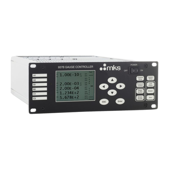
Ctrl Channel System Setup Setup 1.00E-10 Ctrl Pressure Leak Control Check Degas Beeper 1.20E-03 On/off SP10 Sensor 3.50E-02 SP11 Zero On/Off SP12 Enter Remote Figure 3-1 937B front Panel. Comm RS232/485 Figure 3-2 937B rear panel. MKS 937B Operation Manual... - Page 19 Power Switch AIO Module AC Power Inlet RS232/485 Communication Port Relay Output Port Analog Output Port Communication/Valve Control Module Cold Cathode Module High Voltage BNC connector Current BNC connector Pirani Module, MFC Module Capacitance manometer Module MKS 937B Operation Manual...
-
Page 20: Typical Applications For The Series 937B Controller
4 Typical Applications for the Series 937B Controller The measurement of pressure in high vacuum chambers. Pressure control in high vacuum systems and process sequencing using relay set points. Sensing abnormal pressure events and initiating and controlling appropriate security measures using the relay set points. -
Page 21: Hps Products Series 937B Multi-Sensor High Vacuum System
A number of different MKS pressure sensors, listed below can be connected to the 937B: MKS Baratron Capacitance Manometers with heads from 0.02 to 20,000 torr (up to 6) MKS 423 I-MAG or Series 421/422 Cold Cathode Sensors (up to 3) ... - Page 22 Twelve (12) mechanical relays with independently adjustable controller relay set points allow the 937B to control the operation of critical components in a vacuum system such as valve or a pump. The set point parameters are nonvolatile, remaining unchanged after powering down or during a power failure.
-
Page 23: Operating The Series 937B Controller
Power Turn the Power switch on the front panel to Off when the Series 937B Controller is not in use. After turning the Controller off, allow it to remain off for at least 5 sec before turning it back on. -
Page 24: Figure 6-1 Standard 937B Lcd Front Panel Display For Pressure Measurement (A) Leak Detection Mode; (B) Mfc Ratio Or Valve Control Mode
REMOTE Figure 6-1 Standard 937B LCD front panel display for pressure measurement (a) Leak detection mode; (b) MFC Ratio or Valve control mode. Type of sensor detected (CC = cold cathode, HC = hot cathode, PR = Pirani, CP =... -
Page 25: Large Font Displays
System Setup 6.4.1 Overview of 937B System setup An overview of the 937B system setup parameters is shown in Figure 6-3. The default values and the selection ranges for these parameters are also shown. MKS 937B Operation Manual... -
Page 26: Display System Setup Parameters
The system setup allows the user to set parameters such as pressure unit, communication protocol, communication address, baud rate, communication command mode (either matching old 937A, or new 937B), disable/enable set parameter, disable/enable user calibration, and FW versions for the controller and boards in the controller box. -
Page 27: Change And Save A Parameter Value
System FV Information Set DAC Parameter Figure 6-4 System setup information displayed on 937B LCD screen. 6.4.3 Change and save a parameter value To change and save a system setup parameter value, use the following procedure: 1. Press any of the keys to move the cursor to the parameter to be changed. -
Page 28: Description Of The System Setup Parameters
38400, 57600, 1152000. The default value is 9600. 5. Command Mode This allows the use of either new 937B or old 937A serial communication protocols. The default setting is 937B. When 937A is selected, 937A software can communicate with the 937B controller. - Page 29 8. Set MFC Ratio Ctrl MFC Ratio Ctrl is available only when one or more MFC boards are present in the 937B. To set MFCs to ratio control mode, change the Set MFC Ratio Ctrl parameter Enter OFF to ON, then, press , the ratio control setup screen will be displayed as shown in Figure 6-14.
-
Page 30: Figure 6-5 System Firmware And Serial Number Information Displayed On 937B Lcd Screen
Version Number Figure 6-5 System firmware and serial number information displayed on 937B LCD screen. 11. Set DAC Parameter The Log/Linear analog output for each individual channel, as well as the combination analog output can be accessed by adjusting the DAC parameter. To view or modify the DAC... -
Page 31: Channel Setup For Pressure Measurement
Press to save the setting. An overview of the 937B Channel Setup options is shown in Figure 6-7. There are five types of sensor setup interfaces available. All of the variable parameters associated with the vacuum sensors, along with the ranges for these parameters are summarized in the Figure. The type of sensor is... - Page 32 BELOW SET SP 1.0E-05 Hyst 1.5E-05 BELOW Control SP 5x10 to 5.0x10 torr Enable Pirani/CP Channel or NA, auto-detected SET SP 1.0E-03 5x10 to 5x10 torr for PR Hyst 1.5E-03 2x10 to 5x10 torr for CP MKS 937B Operation Manual...
-
Page 33: Setup For A Capacitance Manometer
Only ABS (absolute) capacitance manometer is available. 2. Input Voltage The Input Voltage (for the 937B controller) is same as the maximum analog output voltage of the capacitance manometer. To select the correct value, move the cursor to the Input Voltage... -
Page 34: Figure 6-8 Capacitance Manometer Setup Information Displayed On The 937B Lcd Screen
5.35E+01 Auto-detected Figure 6-8 Capacitance manometer setup information displayed on the 937B LCD screen. 4. Factory Default When YES is selected for Factory Default, the Manual Zero data is removed, and its value is reset to zero (factory default). The default setting is NO. -
Page 35: Table 6-1 Valid Gauges For Autozeroing Capacitance Manometers Of Different Ranges
(less than) the setpoint. The default setting for DIR is BELOW. Figure 8-1 provides a more a detailed description of the DIR setting. 10. SET SP MKS 937B Operation Manual... -
Page 36: Setup For A Pr (Pirani)/Cp (Convection Pirani) Sensor
3.0E-01 3.3E-01 Auto-detected Figure 6-9 Pirani/Convention Pirani setup information that is displayed on the 937B LCD screen. 1. Sensor Type The Senor Type is often auto-detected during the initial power up the Pirani or Convection Pirani sensor. If the sensor type is auto-detected, a user cannot change the sensor type from the front panel. - Page 37 Relays for each PR/CP channel are preset (2 per channel) as shown below. These values are auto-detected. Sensor location Relay assigned 1 & 2 3 & 4 5 & 6 7 & 8 9 &10 11 & 12 9. Enable There are three ways to enable a relay: MKS 937B Operation Manual...
- Page 38 When the power to the Pirani is turned on, a time delay is added to avoid having an ion gauge being turned on at high pressure when a potential inaccurate transient pressure indication may occur while the power-up for PR/CP sensor is in progress. MKS 937B Operation Manual...
-
Page 39: Setup A Cold Cathode Sensor
1.0E-03 1.2E-03 Figure 6-10 Cold cathode setup information as displayed on 937B LCD screen. 3. AO Delay The Analog Out Delay function prevents the activation of the cold cathode sensor's setpoint relays and maintains their outputs in the OFF state until the delay has expired. The range is from 3 to 300 seconds and the default value is 3 seconds. - Page 40 1.0x10 torr. The default value is 5.0x10 torr. It is enabled at all times in the 937B. When the Protect Setpoint is triggered, the Auto control is disabled. The gauge can then be turned on only manually or by serial command. This is due to the fact that the gauge control setpoint should normally act first.
-
Page 41: Setup A Hot Cathode Sensor
The comparator controls an opto-isolated solid state relay, which enables the fast control of an external device. 6.5.5 Setup a Hot Cathode Sensor Refer to Figure 6-11 for setting up a Hot Cathode sensor. 1. Gas Type MKS 937B Operation Manual... -
Page 42: Figure 6-11 Hot Cathode Setup Information Displayed On 937B Lcd Screen
2.0E-08 1.8E-09 Relay 04 CLEAR BELOW 5.0E-07 5.5E-07 Control SP SAFE 1.0E-03 1.2E-03 Figure 6-11 Hot cathode setup information displayed on 937B LCD screen. Symbol Relative correction factor to N 1.00 Argon 1.29 Carbon Dioxide 1.42 Deuterium 0.35 0.18 Helium Hydrogen 0.46... - Page 43 SET: force the relay to activate (close) regardless of pressure and setpoint values CLEAR: force the relay to deactivate (open) regardless of pressure and setpoint values. ENABLE: relay status is determined by the pressure, setpoint value, and direction. MKS 937B Operation Manual...
- Page 44 OFF: Even if the control channel is selected, it is not activated. The hot cathode sensor must be turned on/off manually. MKS 937B Operation Manual...
-
Page 45: Power Control Of A Pressure Sensor
Power Control of a Pressure Sensor When a pressure sensor is attached on a 937B controller, the power to the pressure sensor may have to be controlled. For example, turning on a HC sensor at ambient pressure may result in a filament burnout, and lead to permanent damage of the sensor. -
Page 46: Power (Including Degas) Control Of A Sensor Via 37 Pin Aio Dsub Connector
6.6.3 Power (including degas) control of a sensor using Serial communication commands. The following serial communication command turns on/off the channel power for a sensor (PR/CP/CC/HC) connected to 937B remotely. @254CPn!ON;FF Here, n=1 to 6, which is corresponding to the gauge connected to channels A1, A2, B1, B1, C1 and C2, respectively. -
Page 47: Leak Test Using The 937B Controller
1x10 Torr l/s. The principle for detecting a leak with the 937B controller is based on the gas dependency of the pressure reading for the pirani (due to thermal conductivity differences between gases) and the ion... - Page 48 1. With the Controller on, pump down the system to a base pressure. 2. Close a valve to isolate the pump. 3. Measure the rise of the pressure over a time interval. A very fast rise indicates a leak. MKS 937B Operation Manual...
-
Page 49: Channel Setup For Flow Measurement And Control
Channel Setup for Flow Measurement and Control The 937B controller can also be used to operate MKS mass flow controllers. Up to six MFCs can be simultaneously controlled by one 937B. The MFCs can also be used to control the system pressure. - Page 50 The default for this function is NO. Since the MFC and the 937B both control the gas flow, to be correctly zeroed a gas flow must have both the MFC and the 937B be set to zero. The recommended procedure for zeroing a MFC is: ...
- Page 51 Ctrl is changed to ON, it will (1) override the other active control mode within the same channel, and (2) turn off any active PID control in other channel as only one PID control is allowed for a 937B controller. If a currently active PID MKS 937B Operation Manual...
- Page 52 The Recipe function is a collection of control parameters and settings for PID control of a system pressure. In the 937B controller, a maximum of 8 recipes can be defined and set. These can be assigned to any valid PID control channel (either MFC, or valve).
- Page 53 (a) Recipe setup screen for single channel PID Ctrl. Pressure Control Parameter Setting Recipe PID CH P Ctrl Ch Base P Setpoint Preset 5.00E+2 Proportional Start 1.00E+1 Integral Softstart 1.00E+1 1.00E+1 Derivative Direction 1.50E+0 Upstream (b) Recipe setup screen for RatioA Ctrl. MKS 937B Operation Manual...
-
Page 54: Figure 6-13 The Mfc/Valve Control Recipe Setup Screen
During the pressure control process, the 937B calculates the deviation between the current pressure reading and the setpoint; this is the error signal that is multiplied by the Proportional gain setting. The 937B sets the corresponding valve control signal based on the calculated error signal. The MFC/control valve drive signal is thus proportional to the Proportional gain setting and the error signal. - Page 55 The valid range for Integral gain is 0.0001 to 10 1/seconds. The default setting is 0.02 for 937B. Derivative: This is the derivative control parameter for PID control of system pressure. The derivative function creates a valve control signal based on the rate of change in the sensor’s pressure reading (i.e.
- Page 56 To view or edit other recipe, you need to press key to go back to the recipe scan mode where you can select different recipe as described in step 6. Relay MKS 937B Operation Manual...
-
Page 57: Set Mfcs For Ratio Flow And Pressure Control
The maximum gas flow rate for a MFC is limited by its full scale and this, in turn, limits the settings for gas flow ratios., Therefore, the maximum ratio initial setpoint for a MFC in the 937B must be less than ½... -
Page 58: Figure 6-15 Mfc Ratio Control Setup Screen
RatioM off first. You can set the RatioA to ON, and RatioM will be switched off automatically. In addition, the transition between RatioM and RatioA control is smooth. When RatioA is switched to RatioM, the flow rates for all MFCs will maintain at the values when switch is executed (similar to hold MKS 937B Operation Manual... -
Page 59: Pressure Control Using A Control Valve
In this case, a pressure control board must be installed in the COMM slot of the 937B controller. The system pressure can then be controlled by the position of the control valve. -
Page 60: Valve Control Mode
Recipe title. The recipe can then be manually edited by changing the Edit parameter from No to Yes. The detailed recipe parameters are identical to those for MFC based pressure control, as describe in Section 6.8.1. MKS 937B Operation Manual... -
Page 61: Installing Vacuum Sensors
7.1.4 Connecting the Series 421/422 Sensor The Series 421Cold Cathode Sensor and Series 937B Controller are connected using coaxial cables with SHV and BNC connectors as shown below. The Series 422 Cold Cathode gauge is same as 421 except that its end has LEMO connectors. -
Page 62: Connecting The 423 I-Mag Sensor
Use a conductive, all-metal clamp to mount a KF 25 or KF 40 flanged sensor body for grounding. Connect the cable to the Sensor and to the Series 937B Controller before turning on your system. Tighten the thumbscrew on top of the cable to make sure that it is securely in place. -
Page 63: Connecting A Hot Cathode Sensor To The 937B Controller
A sensor cable with a 13 pin D-Sub connector (Figure 7-1) is required for operation and this must be purchased separately from the 937B Controller system. Figure 7-1 13 pin D-Sub connector on the back of 937B HC board. The pin out for the hot cathode connector is described in Table 7-1. Pin #... -
Page 64: Figure 7-2 Lpn Gauge Cable Diagram
Remove power from the controller before connecting or disconnecting the cable from the sensor or controller. Hot cathode cables have several special characteristics, including lethal ® voltages, therefore only cables supplied by HPS Products should be used. MKS 937B Operation Manual... -
Page 65: Installing Pirani Sensors
Do not use a compression mount (quick connect) to attach the Sensor to a system in positive pressure applications. A solid electrical connection between the Sensor and the grounded vacuum system must be provided to shield the tube element from external radiation sources. MKS 937B Operation Manual... -
Page 66: Preparing The 317 Sensor For Bakeout
The sensor cable is connected to the 937B Controller with the 9-pin "D" connector as shown in Figure 7-4. This connector is equipped with integral strain relief. Screw the strain relief into the mating standoffs on the rear of the Controller for good contact and to avoid excess stress on the connectors. -
Page 67: Capacitance Manometers - Mks Baratron
Bridge reference leg Table 7-3 Pin out for 317/345 cables. Capacitance Manometers - MKS Baratron The Series 937B Controller supports a number of capacitance manometers, including the MKS unheated Baratrons (622A, 623A, 626A, 722A ), and MKS 45 C heated Baratrons (624B,D24B, ®... -
Page 68: Figure 7-5 The Wiring Diagram For The Capacitance Manometer Cable
A shielded cable with 9 pin male Dsub on the controller end and a 15 pin male Dsub end on the Baratron end is required to connect the Baratron to the module on the 937B controller. Detailed wiring for the cable is shown in Figure 7-5. -
Page 69: Connecting Relay And Analog Outputs
25 pin D-Sub connector on the back of the AIP module. Relays used in the 937B are normally open (NO) SPDT relays. Thus if no is supplied to the controller, no output signal can be sent. During the 937B power up process, a delay circuit is implemented to ensure that all of these relays are disabled (i.e. -
Page 70: Proper Setting Of A Relay
8.1.2 Proper setting of a relay Several parameters need to be correctly set to properly use the relays in a 937B controller. Figure 8-1 shows that manner in which these parameters are defined. ABOVE BELOW Setpoint Hysteresis Hysteresis Setpoint Relay... -
Page 71: Relay Inductive Loads And Arc Suppression
BELOW, the hysteresis must be higher than the setpoint. When Direction is changed in the 937B controller, a default offset value (about 10%) is given to the hysteresis to avoid above-mentioned problem. Depending on the application, this value may need to be optimized by the user. -
Page 72: Buffered Analog Output
Buffered analog signals are non-linear and strongly sensor dependent, use these signals with due caution. Normal buffered output for the 937B is 0 to 10 V. If a negative buffered voltage is observed, it may be caused by ... -
Page 73: Figure 8-3 Buffered Analog Output For Cold Cathode Gauges (421/422/423) In N
Buffered Cold Cathode Analog Output (N (Series 421 and 423) Pressure, Torr Figure 8-3 Buffered analog output for cold cathode gauges (421/422/423) in N MKS 937B Operation Manual... -
Page 74: Table 8-4 Buffered Analog Output For The Cold Cathode Gauges (421/422/423) In N
2.2 V< V <3.71 V 7722 1969 V>3.71 V 2157 3161 0721557 Table 8-5 Equations for 937B Cold Cathode gauges (N MKS 937B Operation Manual... -
Page 75: Figure 8-4 Buffered Analog Output For Hot Cathode Gauges; Same As The Logarithmic Analog Output
Buffered Hot Cathode Analog Output Pressure, Torr Figure 8-4 Buffered analog output for hot cathode gauges; same as the logarithmic analog output. MKS 937B Operation Manual... -
Page 76: Figure 8-5 Buffered Analog Output For A 345 Pirani Gauge
Buffered Pirani Analog Output (Series 315 & 345) Pressure, Torr Figure 8-5 Buffered analog output for a 345 Pirani gauge. MKS 937B Operation Manual... -
Page 77: Table 8-6 Buffered Analog Output For The 315/345 Pirani Sensors
9.5638 7.9034 1.0E+02 9.5795 7.9149 1.5E+02 9.6017 7.9306 2.0E+02 9.6146 7.9400 3.0E+02 9.6319 7.9539 4.0E+02 9.6454 7.9664 6.0E+02 9.6693 7.9922 8.0E+02 9.6925 8.0200 1.0E+03 9.7157 8.0502 Table 8-6 Buffered analog output for the 315/345 Pirani sensors. MKS 937B Operation Manual... -
Page 78: Table 8-7 Equations For The 315/345 Pirani Sensors
2959 9386 9386 30 <p< 1 torr Helium 0.63<V<10 V <3 torr 3965 Table 8-7 Equations for the 315/345 Pirani sensors. MKS 937B Operation Manual... -
Page 79: Figure 8-6 Buffered Analog Output For The 317 Convection Pirani Gauge
Buffered Convection Pirani Analog Output (Series 317) Pressure, Torr Figure 8-6 Buffered analog output for the 317 convection Pirani gauge. MKS 937B Operation Manual... -
Page 80: Table 8-8 Buffered Analog Output For The 317 Convection Pirani Sensor
7.0109 1.0E+02 8.4917 7.0396 1.5E+02 8.5547 7.0943 2.0E+02 8.6178 7.1523 3.0E+02 8.7804 7.3037 4.0E+02 9.0106 7.5176 6.0E+02 9.3827 7.8191 8.0E+02 9.6467 8.0330 1.0E+03 9.8515 8.1989 Table 8-8 Buffered analog output for the 317 Convection Pirani sensor. MKS 937B Operation Manual... -
Page 81: Table 8-9 Equations For The 317 Convection Pirani Sensor
7436 Helium 0.63<V<10 V <4 torr 3177 Table 8-9 Equations for the 317 Convection Pirani sensor. MKS 937B Operation Manual... -
Page 82: Logarithmic/Linear And Combination Analog Output
Buffered analog output for capacitance manometers. Logarithmic/Linear and combination analog output Since most of the buffered analog outputs are non-linear, logarithmically linearized or linear analog outputs are also provided for each individual sensor. However, since the logarithmic/linear analog MKS 937B Operation Manual... -
Page 83: Logarithmic/Linear Analog Output
DACs inside the controller, they can be modified by setting appropriate DAC parameters in the System Setup screen shown in Figure 6-6. The default analog output for the 937B controller is logarithmic having a slope of 0.6V per decade and ... -
Page 84: Figure 8-8 Setup Screen For Setting Combination Channel Parameters
Set the gauge combination @254SPC1!HH,MM,LL;FF and @254SPC2!HH,MM,LL;FF . Here, HH, MM and LL are the gauge channel (A1, A2, B1, B2, C1, C2, NA) corresponding to the gauge assigned to High, Middle, and Low range pressure gauges. MKS 937B Operation Manual... -
Page 85: Logarithmic/Linear Analog Output When The Gauge Power Is Turned Off
Power off, broken filament 10 V CC & HC only Power off, broken filament 10 V Combined No gauge is assigned 10 V Table 8-10. The expected logarithmic/linear analog output values when the sensors are unpowered. MKS 937B Operation Manual... -
Page 86: Rs232/485 Serial Communication Commands
9 937B RS232/485 Serial Communication Commands Communication protocols Description RS485(-)/RS232TxD/(B) RS485(+)/RS232RxD/(A) Ground Table 9-1 937B serial communication wiring diagram. Cable length with RS232 signals 50 ft (15 m) Cable length with RS485 signals 4000 ft (1200 m) Baud rate 9600, 19200, 38400, 57600, 115200... -
Page 87: Pressure Reading Commands
Combination Channels Read pressure Combined pressure in selected units d.d0Eee (n=1 or 2) on channel n (d,e=0 to 9) and its Combination disabled NAK181 combination sensor Table 9-3 937B pressure reading commands. MKS 937B Operation Manual... -
Page 88: Relay And Control Setting Commands
Query the relay status (relay1 relay 2 …relay 12). (d=0,1,2) 0: clear; 1: set; 2: enable. ddd..ddd Query all 12 relay setpoint status (relay1 relay 2 …relay (d=0,1) 12). 0: clear; 1: set. Table 9-4 937B relay and control serial setting commands. MKS 937B Operation Manual... -
Page 89: Capacitance Manometer Control Commands
Query the channel power status for PR, CP, HC or high (n=1 to 6) voltage status for CC. Turn on/off the channel power for PR, CP, HC, or high voltage for CC). Table 9-6 937B Pirani and Convection Pirani control commands. MKS 937B Operation Manual... -
Page 90: Cold And Hot Cathode Control Commands
(n=1,3,5) output. Only available for special CC board with fast (d,e=0 to 9) (d,e=0 to 9) relay, and the setpoint value needs to between 5x10 2x10 torr. Table 9-7 937B cold and hot cathode control commands. MKS 937B Operation Manual... -
Page 91: Mfc Control Commands
Query or set the X-ray limit for a HC sensor. The valid d.dd Eee d.dd Eee (n=1,3,5) range is from 0 to 1X10 torr. (d,e=0 to 9) (d,e=0 to 9) Table 9-8 937B cold and hot cathode control commands. MKS 937B Operation Manual... -
Page 92: Pressure (Valve) Control Commands
248, 248, control board. Open, Open, Query or set the operation mode for the valve Close, Close, connected to the pressure control board. Hold, Hold, Manual Manual, Auto Table 9-10 937B pressure (valve) serial control commands. MKS 937B Operation Manual... - Page 93 Default is Upstream. PIDR ON, OFF ON, OFF, NAK Start or stop the PID pressure control using current active recipe. Table 9-11 937B pressure (valve) serial control commands. MKS 937B Operation Manual...
-
Page 94: System Commands
7.2. Use n=0 for combination output. (d,e=0 to 9) (d,e=0 to 9) Valid range is from –20 to 20 when DLT is set to LOG, and always equals to zero when DLT is set to LIN. MKS 937B Operation Manual... -
Page 95: Table 9-10 937B System Commands
UNRECOGNIZED MSG INVALID ARGUMENT VALUE OUT OF RANGE INVALID CTRL CHAN CMD QUERY BYTE INVALID NOT 485 CAL DISABLED COMBINATION DISABLED CONTROL SET POINT ENABLED PRESSURE TOO HIGH FOR DEGAS Table 9-13 937B serial communication error codes. MKS 937B Operation Manual... -
Page 96: Emulated Operation And Rs232/485 Serial Communication Commands
However, since significantly more relays (12 relays for the 937B vs. 5 relays for the 937A) and sensors can be connected to the 937B controller, different connectors are used on the 937B, and adaptors are required for the smooth transition. - Page 97 Table 10-3 A description of the pin assignments for adapting the 937A 25 pin connector to the 937B 37 pin connector for analog output and gauge control when a CC board is installed in slot A. When setting the 937B to 937A operation mode, the old 937A communication cable has to be re-wired.
-
Page 98: Communication Protocols
Old 937A Old 937A (232&485) RS232 RS485 RS485(-)/RS232TxD/(B) RS485(+)/RS232RxD/(A) Ground Table 10-4 937B serial communication wire diagram. Cable length with RS232 50 ft (15 m) signals Cable length with RS485 4000 ft (1200 m) signals Baud rate 9600, 19200, 38400, 57600, 115200... -
Page 99: Pressure Reading Commands
(d,e=0 to 9) sensor Above combined range Below combined range NOGAUGE! Sensor missing/misconnected Disabled! No ion gauge is assigned to the channel. Table 10-6 937A pressure reading serial commands. MKS 937B Operation Manual... -
Page 100: Relay And Control Setting Commands
Action taken (n=1,2,4) for CH n PROTECT! Channel is in protected state. CONTROL! Channel is in controlled state. XCCn Disable CC HV Action taken (n=1,2,4) for CH n Table 10-8 The 937A cold cathode control commands. MKS 937B Operation Manual... -
Page 101: User Calibration Commands
Nc: No module in slot in slot CC, A Wc: Wrong module in CC slot and B. Read controller module FW c.cc,m.mm c.cc: Controller version version (c,m=0 to 9) m.mm: Table 10-10 937A system commands. MKS 937B Operation Manual... -
Page 102: Ascii Character Table
10.8 ASCII character table Table 10-11 ASCII character table. MKS 937B Operation Manual... -
Page 103: Maintenance Of Series 937B Controller Modules
11 Maintenance of Series 937B Controller modules There are 3 sensor module slots (A, B, and C) available in the 937B controller. Sensor module plug-in boards (Pirani/CP, capacitance manometer, cold cathode, hot cathode) can be inserted into any available slot and the controller will automatically recognize the type of the board in the slot. Typically, 937B controllers are shipped with customer-specified sensor modules and these are tested at the factory. -
Page 104: Removing And Installing Aio Module
1. Make sure that the 937B power is off and that the power cord is disconnected 2. Using a #1 Phillips screwdriver, remove the four (4) screws on the four corner of the rear panel of the AIO module. -
Page 105: Communication Module
To install the AIO module, please follow the following procedure: 1. Make sure that the 937B power is off and that the power cord is disconnected 2. Align the module to fit and slide freely in the card guides, with the internal 48-pin DIN connector end first. -
Page 106: Mounting The 937B Controller
The power supply used on the 937B controller is a 150 Watt, open frame switching power supply. This power supply is mounted on the right-hand side panel using four screws. Do not remove the power supply. -
Page 107: Mounting The 937B Controller With Another ½ Rack Instrument
® (HPS Part # 100007700) 1. Attach the ½ rack instrument to the 937B controller using the small splicing plate and the four 10-32 bolts provided. The splicing plate is used to connect the front panel of each instrument together. -
Page 108: Maintenance And Service Of Hps Vacuum Sensors
In operation, a near constant circulating electrical current is trapped by the crossed fields in which the collisions between electrons and residual gas molecules produce ions that are collected by the MKS 937B Operation Manual... -
Page 109: Maintenance Of Series 421/422 Cold Cathode Sensor
To disassemble the sensor, remove the backshell subassembly as follows (Steps 1 through 4 are not necessary when replacing internal parts): 1. Remove the two 4-40 x ¼" Phillips head SEMS screws and slide the backshell off of the sensor. MKS 937B Operation Manual... -
Page 110: Figure 12-3 An Exploded View Of The 421/422 Cold Cathode Gauge Assembly
Figure 12-3 An exploded view of the 421/422 cold cathode gauge assembly. 2. Remove the two 4-40 x ¼" button head screws MKS 937B Operation Manual... - Page 111 5 to 20% sodium hydroxide solution, at room temperature (20°C) for one minute. Follow with a preliminary rinse of deionized water. Remove smut (the black residue left on aluminum parts) in a 50 to 70% nitric acid dip for about 5 minutes. MKS 937B Operation Manual...
-
Page 112: Maintenance Of Series 423 I-Mag Cold Cathode Sensor
For grounding, use a conductive, all-metal clamp to mount a KF 25 or KF 40 flanged sensor body. Connect the cable to the sensor and to the 937B Controller before turning on your system. Tighten the thumbscrew on top of the cable to make sure it is securely in place. -
Page 113: Figure 12-4 An Exploded View Of The Series 423 I-Mag Cold Cathode Gauge Sensor
2. Turn off the power to the 937B controller. Flathead Screw (2) Magnet Ion Current High Voltage Feedthrough Pin Feedthrough Pin Glass Insulator Leaf Spring Locating Collar Anode Sensor Body Ground Shield Ceramic Spacer, Small Cathode Grid Washer Ceramic Spacer, Large... -
Page 114: Cleaning The I-Mag Sensor
Chemical cleaning should not be used to clean the anode; mild abrasives or ultrasonic cleaning are acceptable. Do not damage the leaf spring while cleaning the Sensor. Each of the cleaning methods described above should be followed with multiple rinses of deionized water. MKS 937B Operation Manual... -
Page 115: Assembling The I-Mag Sensor
. The measurement should indicate a short circuit between them. There should be an open circuit between the ion current feedthrough pin and both the high voltage feedthrough pin and the sensor body MKS 937B Operation Manual... -
Page 116: Preparing The Sensor For Bakeout
“ion current” and this is proportional to the pressure in the gauge. The “ion current” is measured by the electrometer and converted to a pressure indication on 937B display. The Bayard Alpert (BA) gauge is one of the most popular types of hot cathodes gauges. They are available in glass envelopes, or mounted on a flange (the latter configuration is often referred to as a nude gauge). -
Page 117: Cleaning The Hot Cathode Sensor
5 mA of current. The resistance readings of a normal hot cathode sensor are show in table 12-1. The resistance between the two pins of each filament is of particular importance. This test may be applied to any hot cathode sensor operated by 937B. Pin Numbers Resistance () for a good... -
Page 118: Maintenance Of Pirani Sensors
12.4.1 Theory of a Pirani pressure sensor Both standard Pirani and convection enhanced Pirani gauges can be used with the 937B Controller. In both cases, measurement is based on gas-dependent thermal conductivity of the gas in the vacuum environment. A wire suspended from supports (as shown in Figure 12-7) is heated and maintained at a constant temperature during the measurement process. -
Page 119: Cleaning The Series 345 Sensor
Replace the sensor if it becomes contaminated (see Spare Parts and Accessories). 12.4.2.1 Testing the Series 345 Sensor This procedure tests function only. Lower levels of sensor damage that are due to contamination or rough handling can affect calibration, but the tube may still be functional. MKS 937B Operation Manual... -
Page 120: Cleaning The Series 317 Sensor
Convection Pirani sensor can be baked up to 150°C and the Shielded Convection Pirani sensor can be baked up to 100°C. A 317 sensor is also available with an aluminum housing. With the electronics removed, It is bakable to 250°C. MKS 937B Operation Manual... -
Page 121: Maintenance Of Capacitance Manometer
Exploded view of a MKS Capacitance manometer sensor. MKS capacitance manometers contains a sensor and signal conditioner. The sensor is made up of a tensioned metal diaphragm, one side of which is exposed to the media whose pressure is to be measured. -
Page 122: Repairing The Baratron™ Capacitance Manometer
12.5.2 Repairing the Baratron™ Capacitance Manometer Repair by the user is not recommended since replacement or movement of PC board components may require complete calibration of the unit. Return to MKS for repair. MKS 937B Operation Manual... -
Page 123: Spare Parts And Accessories
Cable for Hot Cathode, Low Power Nude 10 ft (3.0 m) 100010909 25 ft (7.6 m) 100010910 50 ft (15.2 m) 100010911 Cable for 317 Convection Pirani & 345 Pirani Sensor 10 ft (3.0 m) 103170006SH 25 ft (7.6 m) 103170007SH MKS 937B Operation Manual... - Page 124 +13 to +32 VDC input, 0-10 VDC output Accuracy (G) Std, 0.5% of Rdg Connector (Z) 9-pin Type D Sensor, Series 431 Cold Cathode KF 25 104310004 KF 40 104310001 2¾" CF 104310002 1" tube 104310003 MKS 937B Operation Manual...
- Page 125 -F, 0-10V 902-1305 ® ® Please call the HPS Products Customer Service Department of MKS Vacuum Products Group at 1-303-449- 9861 or 1-800-345-1967 to order any of these parts or to receive catalogs for other MKS products. MKS 937B Operation Manual...
-
Page 126: Appendix
Cesium iso-Amylene Iso-C Chlorine 0.68 cyclo-Amylene cyclo-C Argon Chlorobenzene Chloroethane Chloroform CHCl Benzene Chloromethane Benzoic Acid COOH Cyanogen (CN) Bromine Bromomethane n-Butane Cyclohexylene Iso-Butane iso-C Deuterium 0.35 0.38 Cadmium Dichlorodifluoro- methane Carbon dioxide 1.42 Dichloromethane Dinitrobenzene MKS 937B Operation Manual... - Page 127 Cy-C Nitrobenzene Hydrogen 0.46 Nitrogen 0.38 Nitrotoluene (o-,m-,p-) 0.41 Nitric oxide 0.45 0.44 Hydrogen Bromide Nitrous oxide Hydrogen chloride 1.3 to 2.1 Oxygen Hydrogen cyanide Hydrogen fluoride Hydrogen iodide n-Pentane Hydrogen sulfide Iso-Pentane Neo-Pentane Iodine Phenol MKS 937B Operation Manual...
- Page 128 Phosphine Sulfur dioxide Potassium Propane Sulfur hexafluoride 3.7 to 3.9 Toluene Trinitrobenzene Propene oxide Water n-Propene 3.2 to 3.7 cyclo-Propene cy-C Xenon 2.87 Rubidium Silver perchlorate AgClO Sodium o-Xylene Stannic iodide p-Xylene MKS 937B Operation Manual...
-
Page 129: Mfc Gas Conversion Factors For Selected Gases
0.153 4.660 0.38 Freon 13B1 CBrF 0.1113 6.644 0.37 Freon 14 0.1654 3.926 0.42 Freon 21 CHCl 0.140 4.592 0.42 Freon 22 CHClF 0.1544 3.858 0.46 Freon 23 0.176 3.127 0.50 Freon 113 0.161 8.360 0.20 MKS 937B Operation Manual... - Page 130 0.33 1,1,2 Trichloro-1,2,2,-Trifluoroethane (Freon 113) 0.161 8.360 0.20 Tungsten Hexafluoride 0.0810 13.28 0.25 Xenon 0.0378 5.858 1.32 ** Consult MKS Instruments Note: Standard pressure is defined as 760 torr (mmHg). Standard temperature is defined as 0 MKS 937B Operation Manual...
-
Page 131: Product Warranty
THIS PERIOD. Warranty Service The obligations of MKS under this warranty shall be at its option: (1) to repair, replace, or adjust the product so that it meets applicable product specifications published by MKS or (2) to refund the purchase price.
Need help?
Do you have a question about the 937B and is the answer not in the manual?
Questions and answers