Table of Contents
Advertisement
Quick Links
Advertisement
Table of Contents

Related Manuals for MKS 959 Series


Summary of Contents for MKS 959 Series
- Page 1 959 Hot Cathode Controller OPERATION AND MAINTENANCE MANUAL...
- Page 2 959 Hot Cathode Controller November 2000 PART #100011229 Rev. A...
- Page 3 For more information or literature, contact: ® MKS Instruments, Inc., HPS Products 5330 Sterling Drive Boulder, CO 80301 USA Phone: 303-449-9861 800-345-1967 FAX: 303-442-6880 ® 1999 MKS Instruments, Inc., HPS Products. All rights reserved.
-
Page 4: Table Of Contents
Table of Contents Table of Contents 1. Package Contents ..............1 2. Safety Information..............2 2.1 Symbols Used in this Manual ............2 2.2 Safety Precautions ................3 3. Specifications ................ 5 3.1 Controller ..................5 3.2 Standard Pirani ................. 6 3.3 Convection Enhanced Pirani ............ - Page 5 7.3.2.1 Connecting the Series 315 Sensor to the 959 Controller................21 7.3.2.2 Connecting the Series 345 Sensor to the 959 Controller................22 7.3.3 Testing the Series 315/345 Sensor ........ 23 7.4 Series 317 Convection Enhanced Pirani Sensor Installation .. 23 7.4.1 Orienting the Series 317 Sensor ........
- Page 6 8.6.5 Leak Test Mode ..............37 8.7 Front Panel Overview ..............38 8.7.1 Front Panel Switch Definitions ..........38 8.8 Pressure Measurement Modes ............39 8.8.1 Normal Pressure Measurement ..........39 8.8.2 Control Pressure Measurement ..........39 8.8.3 Combined Pressure Measurement ........40 8.9 Set Point Operation ................
- Page 7 8.13.2 Pirani Sensor Leak Test Operation ........56 8.13.3 Hot Cathode Sensor Leak Test Operation ......57 8.14 Status Readouts ................58 8.14.1 Under Pressure ..............58 8.14.2 Over Pressure ..............58 8.14.3 Low Emission ..............59 8.15 Miscellaneous Displays ..............60 8.15.1 LCD Display Test ..............
- Page 8 13.3.2.1 Attention Character ............. A3 13.3.2.2 Device Address ............A3 13.4 Message Handling ................ A4 13.5 ASCII Command Set Definition ............ A4 13.6 Setup Messages ................A5 13.6.1 Set Point Value - SPx ............A5 13.6.2 Control Set Point Value - CSP ..........A6 13.6.3 Protect Pressure - PRO ............
- Page 9 15. Appendix C Gauge Theory ................C1 15.1 Theory of the Thermal Conductivity Gauge ........C1 15.2 Theory of the Hot Cathode Ionization Gauge ......... C3...
-
Page 10: Package Contents
1. Package Contents Before Unpacking your Series 959 Hot Cathode Controller, check all surfaces of the packing material for shipping damage. Please be sure that your Series 959 package contains these items: 1 - Series 959 Controller 1 - female, 15-pin subminiature D Accessory connector kit 1 - 10-foot power cord ®... -
Page 11: Safety Information
2. Safety Information 2.1 Symbols Used in this Manual The first two symbols below, that may be located on your Series 959, identify critical safety concerns. They are used throughout this manual to further define the safety concerns associated with the product. The last two symbols identify other information in this manual that is essential or useful in achieving optimal performance from the 959. -
Page 12: Safety Precautions
Do not substitute parts or modify instrument. Do not install substitute parts or perform any unauthorized modification to the instrument. Return the instrument to an MKS Calibration and Service center for service and repair to ensure that all safety features are maintained. - Page 13 Do not operate in explosive environments. To avoid explosion, do not operate this product in an explosive environment unless it has been specifically certified for such operation. Service by qualified personnel only. Operating personnel must not remove instrument covers. Component replacement and internal adjustments must be made by qualified service personnel only.
-
Page 14: Specifications
3. Specifications 3.1 Controller Measuring Range * 1.0 x 10 to 1.0 x 10 Torr 1.3 x 10 to 1.3 x 10 mbar 1.3 x 10 to 1.3 x 10 Set Point Range * 5.0 x 10 to 9.5 x 10 Torr 6.5 x 10 to 1.2 x 10... -
Page 15: Standard Pirani
Fuse Rating, Size T 1.6 A (5x22mm) Number of Channels Process Control Two nonvolatile, independently set, pressure dependent set point relays Relay contact Rating 2A @ 30 VAC or 30 VDC resistive load, SPDT Relay response < 1000 msec Front Panel Controls Momentary push buttons Range for Sensor Sensitivity 0.1 to 99 Torr... -
Page 16: Convection Enhanced Pirani
Operating Temperature Range 0 to 50 C (32 to 122 Maximum Bakeout Temperature C (122 Diameter 1.3 in. (34 mm) Length 4.4 in. (112 mm) Typical Weight (with KF Flange) 0.5 lb (0.2 kg) Vacuum Connection NW 16 KF, NW 25 KF 1/8”... -
Page 17: Low Power Nude Tube
Diameter 1.6 in. (41 mm) Length 4.4 in. (112 mm) Typical Weight (with KF Flange) 0.5 lb (0.2 kg) Vacuum Connection NW 16 KF NW 25 KF 1/8” NPT-M, with 1/2” compression seal option ® 4VCR F (1/4”) ® 8 VCR F (1/2”) 1 1/3”... -
Page 18: Mini Ba
Operating Temperature Range to 50 C (32 to 122 Bakeout Temperature C (with cable attached) C max, with CF, cable removed â C max, with KF and Viton Seal, cable removed Typical Weight (with CF Flange) 0.9 lb (0.4 kg) Vacuum connection ”... - Page 19 Bakeout Temperature C (with cable attached) C max, with CF, cable removed â C max, with KF and Viton Seal, cable removed Typical Weight (with CF Flange) .816 lb (.36 kg) Vacuum connection 1” OD Tube ” mini CF ” CF NW 25 KF NW 40 KF NW 16 KF...
-
Page 20: Front View
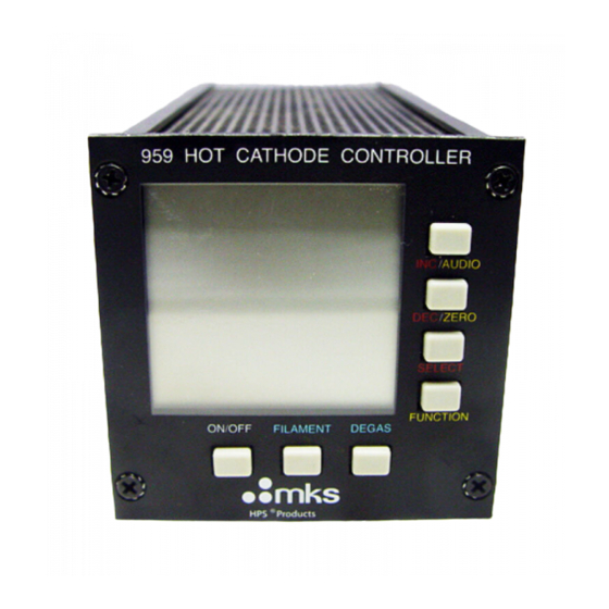
4. Feature and Control Locations 4.1 Front View 4.2 Rear View 959 Hot Cathode Controller... -
Page 21: Side View
4.3 Side View Liquid Crystal Display (LCD) Power On/Off Push Button Switch Filament Power Push Button Switch Degas Power Push Button switch Function Menu Push Button Switch Item Selection Push Button Switch Decrement/Leak Test Zero Push Button Switch Increment/Leak Test Beeper Push Button Switch Pirani Sensor Connector, Female, 9 pin, “D”... -
Page 22: Standard Pirani
4.4.1 Standard Pirani 315 Standard Pirani Sensor Sensor Vacuum Port Male Octal Socket 345 Standard Pirani Sensor Sensor Vacuum Port Male 9 Pin “D” connector 959 Hot Cathode Controller... -
Page 23: Convection Enhanced Pirani
4.4.2 Convection Enhanced Pirani 317 Convection Enhanced Pirani Male, 9-pin “D” connector Sensor Vacuum Port 4.4.3 Low Power Nude Tube LPN Hot cathode sensor Filament 1 Filament 2 Grid and Supports Ion Collector Sensor Vacuum Port and Flange 959 Hot Cathode Controller... -
Page 24: Mini Ba
4.4.4 Mini BA Mini BA Sensor Call outs Sensor Vacuum Port Sensor Cable Connection Male Sensor Socket Pins 959 Hot Cathode Controller... -
Page 25: Typical Applications For The 959 Hot Cathode Controller
5. Typical Applications for the 959 Hot Cathode Controller Measurement of Base Vacuum Control of high vacuum systems and process sequencing using relay setpoints Sensing abnormal pressure and taking appropriate security measures using relay set points Controlling system pressure using analog output as input to an automatic pressure controller Starting or stopping system processes with relay set points Measuring pressures of backfilled gases... -
Page 26: About The 959 Hot Cathode Controller
6. About the 959 Hot Cathode Controller ® The HPS Products Series 959 Hot Cathode Controller provides accurate and reliable pressure measurement from 10 Torr up to 10 Torr, or to 1000 Torr with the optional Convection Enhanced Pirani module. Designed with versatility and ease-of-use in mind, the large liquid crystal display (LCD) shows the Pirani and Hot Cathode readouts simultaneously. - Page 27 Set Points Two independently adjustable relay set points are available. They may be set or disabled from either the front panel or by RS232. The set points are nonvolatile, remaining unchanged after powering down or during a power failure. Leak Test With the Leak Test mode, medium to gross leaks can be found by utilizing the indirect measurement properties of the Hot Cathode and Pirani sensors and a tracer gas other than air.
-
Page 28: Installing The 959 Hot Cathode Controller
7. Installing the 959 Hot Cathode Controller 7.1 Controller Installation 7.1.1 Controller Mounting The Series 959 Hot Cathode Controller is designed for either panel mounting or for stand-alone use. Regardless of the method you choose, assure adequate ventilation to the Controller with at least a 1/2 of an inch left open above and below the perforated panels. -
Page 29: Locating A Pirani Sensor
and uses a DB9 connector on the sensor. The two series also have different bakeout temperature ranges, with versions of the 315 able to withstand temperatures up to 280 The Convection Pirani sensor design enhances heat transfer at higher pressures through convection. This sensor will read continuously from 1x10 to 1000 Torr. -
Page 30: Series 315 / 345 Standard Pirani Sensor Installation
To install a Sensor fitted with a ” , do not use the case for tightening. Use the 9/16” hex flats on the sensor’s tubulation with a wrench for tightening. Wrap about two turns of Teflon ® seal tape on the threads of the sensor in the direction of the threading to ensure a leak-free seal. -
Page 31: Connecting The Series 345 Sensor To The 959 Controller
Turn off the Controller before connecting or disconnecting the cable from the Sensor or Controller. Pin 6 of the octal socket is intentionally shorter as a safety measure. When the cable is connected or disconnected from the Sensor, this feature prevents a voltage overload on the Sensor in case the Controller has not been shut off. -
Page 32: Testing The Series 315/345 Sensor
7.3.3 Testing the Series 315/345 Sensor This test is for function only. Slight damage by contamination or rough handling can affect calibration, but the sensor may still indicate pressure. The most common cause of sensor failure is a broken filament due to improper handling. -
Page 33: Testing The Series 317 Sensor
When exerting excessive stress on the cable, use separate strain relief to prevent damage to the Sensor or Controller . Cables are available in standard lengths of 10, 25, 50 and in custom lengths up to 500 feet. Connect the cable to the rear of the Controller at the Gauge port. Tighten the connector jackscrews into the mating screw locks to ensure proper electrical connection and to prevent stress on the connectors. -
Page 34: Low Power Nude Tube And Mini Ba Hot Cathode Sensor Installation
7.5 Low Power Nude Tube and Mini BA Hot Cathode Sensor Installation 7.5.1 Locating a Hot Cathode Sensor Locate the sensor where it can measure chamber or manifold pressure. Installing the sensor away from pumps and gas sources gives the most representative pressure measurement. -
Page 35: Connecting A Hot Cathode Sensor To The 959 Controller
seal is discouraged because outgassing and/or permeation through the elastomer can cause errors in the pressure measurement. A sensor with a KF flange and an elastomer O-ring is suitable only for pressure measurement down to 1 x 10 Torr. When inserting a nude type sensor into a port, do not bend, damage, move the electrodes or feed through pins. -
Page 36: Testing The Hot Cathode Sensor
7.5.6 Testing the Hot Cathode Sensor This test will only identify a nonfunctioning sensor. This will not detect damage from contamination, misuse or rough handling that affects calibration of a functioning gauge. The most common cause of sensor failure is filament failure. To check for this failure, test the sensor using an ohmmeter with less than 5 mA of current. -
Page 37: Sensor Cable Diagrams And Pin Outs
7.6 Sensor Cable Diagrams and Pin Outs 7.6.1 Series 315 959 Hot Cathode Controller... -
Page 38: Series 345 And Series 317
7.6.2 Series 345 and Series 317 Customizing a Series 317 and 345 series Sensor Cable 959 Hot Cathode Controller... -
Page 39: Low Power Nude Tube
7.6.3 Low Power Nude Tube 7.6.4 Mini BA 959 Hot Cathode Controller... -
Page 40: Hot Cathode Connector Pin Out
7.6.5 Hot Cathode Connector Pin Out 4 3 2 1 7 6 5 HOT CATHODE Pin # Description Emission Current Out Emission Current In Factory Test Factory Test LPN Sensor Detect Sensor Detect Common Mini BA Sensor Detect Not Used Collector Current Grid Filament 2... -
Page 41: Accessory Connector
7.7 Accessory Connector Pin # Description Relay 1 NC Relay 1 NO Relay 2 common RS232 RCV Analog Ground Pirani Analog Output Not Used Digital Ground Relay 1 Common Relay 2 NC Relay 2 NO RS232 TX Combined Analog Output Hot Cathode Analog Output Not Used 7.8 AC Power... - Page 42 Do not exceed the rated line voltage of your unit. Electrical shock may result. 959 Hot Cathode Controller...
-
Page 43: Operating The 959 Hot Cathode Controller
8. Operating the 959 Hot Cathode Controller 8.1 How the 959 Hot Cathode Controller Works The 959 Controller consists of 3 microprocessor-based modules. Each module contains embedded firmware dedicated toward a specific aspect of the Controller operation. The three modules coordinate their behavior via real time serial communications across a shared I C bus. -
Page 44: Hot Cathode Sensor Module Operation
The Controller supports two relay set points and can be configured to open or close a relay based on the pressure reading. The DCM evaluates each pressure reading and drives the relays correspondingly. The two sensor modules measure pressure over different ranges of vacuum. -
Page 45: Pirani Sensor Module Operation
8.4 Pirani Sensor Module Operation The sensor module’s primary function is to continuously measure pressure. Measuring pressure consists of: Reading the analog hardware with the A/D; Converting it to pressure; Applying correction or calibration factors to the reading; Computing the corresponding linearized analog voltage; Outputting that voltage to the Pirani D/A;... -
Page 46: Set Point Mode
values can be entered programmatically via the serial link. Operational parameters entered via the serial link while in Pressure Measurement mode take immediate effect. 8.6.2 Set Point Mode In Set Point Mode, the front panel switches are used to enter the various set point parameters that are available for use with the controller. -
Page 47: Front Panel Overview
8.7 Front Panel Overview The following picture shows the 959 controller display. Not all LCD annunciators depicted are used during the operation of the 959 Controller. In addition to the LCD, there is a keypad of 7 momentary push button switches on the controller’s Front Panel for manual control and configuration of the unit. -
Page 48: Pressure Measurement Modes
the type of value being adjusted. The Increment key supports a hold operation - holding the key down will automatically increment the selected value. The rate of automatic increment increases the longer the INC key is pressed. The Increment key has a special definition when the controller is operation in the Leak Test Function mode. -
Page 49: Combined Pressure Measurement
8.8.3 Combined Pressure Measurement In Combined Pressure Measurement mode, the readings of both sensors are evaluated and combined into a single pressure measurement. Only the single, combined pressure measurement is displayed on the LCD. This mode allows the user to have a single, smooth output continuously available from UHV through atmosphere. -
Page 50: Sensor Module Exceptions And Set Point Operation
8.9.2 Sensor Module Exceptions and Set Point Operation When the Hot Cathode filament power is removed, set point relays assigned to the Hot Cathode sensor module are de-energized. When filament power is reasserted, enabled set point relay signals are driven based on the value of subsequent Hot Cathode pressure readings. -
Page 51: Set Point 1 Enable
independent of a particular sensor, that is, the user selects a pressure and the controller determines the sensor to be used to detect that pressure. This display comes up depicting the current set point name and value. Pressing the INC and DEC buttons modifies the bottom display through the range of pressures available to the controller, based on the modules present, until the maximum or minimum values are reached. -
Page 52: Set Point 2 Value Assignment
8.9.6 Set Point 2 Value Assignment This display allows the user to assign a pressure value to Set Point 2. Each time this menu is entered, the current default Set Point 2 value is displayed. A value of 5.0 x 10 Torr is the factory default value. -
Page 53: Control Set Point Operation
8.9.8 Control Set Point Operation The Pirani sensor can be configured to control the Hot Cathode sensor. This mode of operation is only available when both sensors are connected and operational. The control function is implemented by having the Pirani turn on or off the Hot Cathode’s filament power. The Control Set Point is the pressure measurement value used by the Pirani to make its decision. -
Page 54: Control Set Point Assignment
8.9.10 Control Set Point Assignment This display allows the user to assign a Control Set Point. Each time this menu is entered, the current default Control Set Point value is displayed. A value of 1.0 x 10 Torr is the factory default value. -
Page 55: Protect Set Point Operation
8.9.12 Protect Set Point Operation The Protect Set Point is the pressure value that automatically turns off the Hot Cathode’s filament power. The Protect Set Point prevents damage to the Hot Cathode sensor from exposure to high pressure. The Protect Set Point can range from 1.0 x 10 Torr through 1.0 x 10 Torr. -
Page 56: Set Up Configuration
8.10 Set Up Configuration Pressing the FUNCTION key while in Set Points mode places the Controller in Set Up mode. Set Up mode provides access to the controller’s non-set point configuration parameters. While in Set Up configuration mode, the user uses the SELECT push button to sequence through the list of configurable set up attributes. -
Page 57: Combined Mode Constraints
This display allows the user to enable or disable the combined Pressure Measurement mode. The lower read out depicts the current value. Pressing the INC and DEC button toggles the bottom display between ON and OFF. Pressing the SELECT key advances the display to the next item in the menu list 8.10.3 Combined Mode Constraints The controller can only be put into Combined mode when both sensors (Hot Cathode and Pirani) are installed and operational. -
Page 58: Calibration
8.11 Calibration 8.11.1 Pirani Calibration may be necessary if the vacuum or atmospheric reading of the sensor has drifted or the sensor has been replaced. The calibration provided by the 959 controller is designed to improve accuracy of the sensor reading; however, it does not provide NIST traceable calibration. Also, this feature is not intended to correct the output of the sensor for different gases. -
Page 59: Pirani Atmospheric Calibration
8.11.4 Pirani Atmospheric Calibration This display allows the user to calibrate the Pirani sensor reading for atmospheric pressure. This operation is only available when the Pirani module is installed in the controller. The calibration operation makes use of the display’s U indicator to depict atmospheric calibration. -
Page 60: Emission Current Assignment
8.11.6 Degas Time This display allows the user to adjust the length of time Degas power is applied to the filament. Degas time has minimum and maximum limits. The lower read out displays the current degas time, in minutes. The INC and DEC buttons adjust this time up or down, with 1 minute resolution. -
Page 61: Leak Test Operation
8.12 Leak Test Operation 8.12.1 Entering Leak Test Mode Leak Test mode is entered when the user has pressed the Front Panel function key until it selects Leak Test mode. Leak Test mode can only be entered via the front panel; Serial communications does not support Leak Test mode. -
Page 62: Exiting Leak Test Mode
8.12.4 Exiting Leak Test Mode The user terminates the leak test operation by pressing either the SELECT key or the FUNCTION key. Pressing the SELECT key terminates the operation and re-displays the leak test sensor selection display on the LCD. The Controller remains in Leak Test Mode and the user can again select the leak test sensor. - Page 63 This is activated when the controller is switched to the leak test mode. The pressure indication remains visible. Audible indication of leak signals is user selectable from the front panel. While the leak test sensitivity varies with the pressure range, in the best case, it is as low as 10 Torr-liters/second.
- Page 64 If the leak test method outlined above fails to indicate the location of a leak, consider that unexpected high pressures may be caused by a virtual leak, that is, outgassing of a system component. The Series 959 can be used effectively to locate outgassing parts or virtual leaks as well as true gas leaks using the “rate of pressure rise”...
-
Page 65: Leak Test Displays
8.13 Leak Test Displays The Leak Test mode is entered by pressing the FUNCTION key until the LEAK TEST display appears on the bottom of the LCD. While in Leak Test mode, the user uses the SELECT push button to sequence through the list of configured leak test attributes. -
Page 66: Hot Cathode Sensor Leak Test Operation
8.13.3 Hot Cathode Sensor Leak Test Operation This example is for when the leak sensor is the Hot Cathode sensor. If the Hot Cathode sensor is off (e.g. the filament is off) the sensor display indicates the sensor is off, and the leak display read out does not function. -
Page 67: Status Readouts
8.14 Status Readouts Normal pressure measurement operation of the controller may occasionally generate status information on the 16 segment displays other than the typical numeric pressure measurement values. This information reflects internal operational status or errors, pressure over or under range conditions or other situations that do not normally occur, and so do not have dedicated annunciators. -
Page 68: Low Emission
8.14.3 Low Emission The controller will automatically remove filament power from the Hot Cathode sensor when it detects a low emission current. The following display is depicted to inform the user this event has occurred. Only the Hot Cathode module’s read out is affected. The LCD display indicates power is removed from the Hot Cathode filament. -
Page 69: Miscellaneous Displays
8.15 Miscellaneous Displays The following menu displays are used to display and modify controller parameters that do not need to be accessed by the user under normal operating conditions. The displays are accessed by pressing pairs of key combinations simultaneously while in Pressure Measurement mode. Pressing the FUNCTION key at any time returns the controller to the Pressure Measurement mode. -
Page 70: Factory Reset
8.15.2 Factory Reset The display is invoked by pressing the INC and DEC keys simultaneously while in Pressure Measurement mode. This menu display allows the user to reset the controller back to ALL factory set parameter values. The controller will lose all the set up values entered by the user after this reset has executed. -
Page 71: Buffered Analog Output
8.16 Buffered Analog Output Up to three separate analog outputs are provided, the Hot Cathode sensor’s analog output, the Pirani sensor’s analog output and the combined sensors’ analog output. All analog outputs are log-linear. (I.e. the output will be linear on a semilog plot of pressure vs. output voltage). All output voltages have identical volts/decade scales. -
Page 72: Standard Pirani Pressure To Voltage Curve
8.17 Standard Pirani Pressure to Voltage Curve 8.18 Standard Pirani Pressure to Voltage Table Pressure Vout Pressure Vout Pressure Vout Pressure Vout Pressure Vout Pressure Vout 0.010 6.00 0.00010 4.00 0.0010 4.50 0.100 5.50 1.00 10.0 6.50 0.012 6.04 0.00012 0.0012 4.54 5.04... -
Page 73: Convection Enhanced Pirani Pressure To Voltage Curve
8.19 Convection Enhanced Pirani Pressure to Voltage Curve 8.20 Convection Enhanced Pirani Pressure to Voltage Table Pressure Vout Pressure Vout Pressure Vout Pressure Vout Pressure Vout Pressure Vout 0.100 6.50 0.0010 4.50 0.0100 5.00 1.00 6.00 10.0 100.0 7.00 0.120 6.54 0.0012 0.0120... -
Page 74: Hot Cathode Curves
8.21 Hot Cathode Curves 959 Hot Cathode Controller... -
Page 75: Maintaining The 959 Hot Cathode Controller
9. Maintaining The 959 Hot Cathode Controller 9.1 Cleaning the Controller Front Panel The 959 Controller front panel is designed to resist most Laboratory solvents. It can be cleaned with water or isopropyl alcohol. Do not use acetone on the front panel. 9.3 Servicing the Controller The 959 Controller is designed to be maintenance-free under normal operation. -
Page 76: Replacing The Power Fuse
9.3 Replacing the Power Fuse The Series 959 controller has a combined fuse holder and power inlet on the rear panel. Replace the fuse following the steps below. Unplug the power cord from the power source and the Controller. Snap out the fuse holder drawer. Replace the fuse(s) with the following time-lag fuse: ¨... -
Page 77: Using The 959 Hot Cathode Controller With Other Gases
10. Using the 959 Hot Cathode Controller with Other Gases A Hot Cathode ionization sensor measures pressure by the degree of ionization of a gas, so the pressure reading depends on the type of gas in the system. The Series 959 System is calibrated to read pressure for air or nitrogen. -
Page 78: Relative Sensitivity Table
10.1 Relative Sensitivity Table Symbol Sensitivity 1.00 Argon 1.29 Carbon Dioxide 1.42 Deuterium 0.35 Helium 0.18 Hydrogen 0.46 Krypton 1.94 Neon 0.30 Nitrogen 1.00 Nitrogen Oxide 1.16 Oxygen 1.01 Sulfur Hexafluoride 2.50 Water 1.12 Xenon 2.87 Hot Cathode Sensitivities Relative to Nitrogen 959 Hot Cathode Controller... -
Page 79: Accessories
11. Accessories Accessory Connector Kit 100005087 Sensor, Hot Cathode, Mini BA Gauge, Yr Coated Ir Filaments 1” OD Tube 100011085 Mini CF 100011111 100011112 KF25 100011113 KF40 100011114 KF16 100011118 ” OD Tube 100011127 Sensor, Hot Cathode, Low Power Nude KF40, Tungsten Filaments 100005987 ”... - Page 80 959 Hot Cathode Controller User’s Manual 100011229 ® Please call the HPS Products Customer Service Department of MKS Vacuum Products Group at 303-449-9861 or 800-345-1967 to order any of these parts or to receive catalogs for other MKS Products. 959 Hot Cathode Controller...
-
Page 81: Product Warranty
PERIOD. NO WARRANTIES, EXPRESS OR IMPLIED, WILL APPLY AFTER THIS PERIOD. Warranty Service The obligations of MKS under this warranty shall be at its option: (1) to repair, replace, or adjust the product so that it meets applicable product specifications published by MKS or (2) to refund the purchase price. -
Page 82: Appendix A Serial Communications
All responses generated by the controller are in upper case. 13.1.2 Message Compatibility The message format used for the 959 controller mimics that used by the MKS 689 transducer. Whenever possible, identical commands are used to reference identical operations. Commands for new or enhanced 959 capabilities are defined using the same 2 or 3 character keyword philosophy established for the 689. -
Page 83: Message Syntax
13.2 Message Syntax In the following descriptions, the ‘<‘ and ‘>’ characters are used as message field delimiters. They are not part of the commands, and serve only to enhance readability. 13.2.1 Command Syntax The basic command syntax to the controller from the host is as follows: <command field>... -
Page 84: Addressed Rs232
13.3 Addressed RS232 Traditional RS232 communications depends on serial UARTs to detect communications failures with stop bits, parity bits and bit transfers rates. This mechanism doesn’t always detect data bit errors that generate valid characters, but garbled messages. Additional robustness can be added to the communications by defining a formal message syntax that unambiguously identifies the start of each new message. -
Page 85: Message Handling
by the 959 controller use 000 in the address field. The 000 represents the address of the host computer. 13.4 Message Handling A message is defined to begin with an attention character and end with a valid terminator. There is no time limit between characters. Whenever an attention character is detected, any current characters in a device receive buffer are flushed and a new message handling sequence is begun. -
Page 86: Setup Messages
In the following command definitions, words in boldface type indicate exact ASCII text messages, parameters or responses issued between the host and the controller. Each of the command examples has an assumed ‘ACK;FF’ response. To enhance readability that response is not shown. The actual terminator in the following examples is ‘;FF’. -
Page 87: Control Set Point Value - Csp
13.6.2 Control Set Point Value - CSP Description: Assigns the Control Set Point value. This is the value at which the controller will supply power to the Hot Cathode sensor filament. At pressures above this value, power is removed from the Hot Cathode filament;... -
Page 88: Protect Pressure - Pro
13.6.3 Protect Pressure - PRO Description: Assigns the protection pressure for the Hot Cathode sensor. This is the value at which the Hot Cathode sensor’s filament will automatically have power removed from it so that it can be protected from exposure to high pressures. -
Page 89: Gauge Correction - Gc
13.6.4 Gauge Correction - GC Description: Assigns the sensitivity value for the Hot Cathode controller. The 959 controller is calibrated for air/ nitrogen (gas correction factor = 1.0) and has a nominal Hot Cathode gauge sensitivity factor of 9.0/ Torr. The Gauge Correction factor is used to modify the controller sensitivity for gases other than nitrogen. -
Page 90: Atmospheric Calibration -Atm
13.6.5 Atmospheric Calibration -ATM Description: Calibrates the pirani sensor to use the assigned pressure as atmospheric pressure. The corrected pressure value is reflected in the controller voltage output, the programmed response to the Pressure Measurement command and the Set Point signal operation. -
Page 91: Vacuum Calibration - Vac
12.6.6 Vacuum Calibration - VAC Description: Calibrates the Pirani sensor for a baseline vacuum pressure. The user places the sensor into a chamber of low pressure and uses this command to signal the controller to perform a vacuum measurement. The sensor readings are then calibrated to use the current pressure value as vacuum. -
Page 92: Time To Degas -Td
13.6.7 Time to Degas -TD Description: Assigns the length of time of the Degas operation, in minutes. The Time to Degas query returns the assigned time in minutes. The Degas Status query returns the amount of time remaining in the current Degas operation, in minutes. -
Page 93: Front Panel Lock - Fpl
13.6.8 Front Panel Lock - FPL Description: This command enables or disables the Controller’s front panel set up switches. When the front panel is locked, the front panel set up switches are disabled, and the user can only enter controller set up parameters remotely via the RS232 serial communications link. -
Page 94: Factory Default - Fd
13.6.9 Factory Default - FD Description: Places the controller into a known state. This command modifies many device operation setup values and should only be used with caution. After the Factory Default command has been issued, the device has the following configuration set values: Front Panel unlocked Filament Power: Off... -
Page 95: Control Messages
13.7 Control Messages These messages are used to coordinate the actual run time operation of the controller. 13.7.1 Active Filament - AF Description: Selects the active filament. Switching filaments can only take place with power removed from the filament circuitry. Attempts to switch filaments with power applied will automatically remove power from the filament and the user will have to resend the filament power on command (FP). -
Page 96: Filament Power - Fp
13.7.2 Filament Power - FP Description: Turns power on and off to the Hot Cathode emission filament. Keyword: Type: Command only Parameter: Enumerated ASCII text Limits: Reset Value: Query Response: Related Keywords: AF, FS Examples Command: FP!ON; FP!OFF; 959 Hot Cathode Controller A-15... -
Page 97: Degas Power - Dg
13.7.3 Degas Power - DG Description: Turns gauge Degas on and off. Once initiated, the Degas operation will automatically complete and turn itself off. Degas can be arbitrarily turned off with this command. The query returns the current state of the Degas operation, on or off. Degas power cannot be turned on if the filament power has not been turned on. -
Page 98: Combined Pressure Measurement - Cmb
13.7.4 Combined Pressure Measurement - CMB Description: Enables or disables the combined sensor pressure measurement operation. When enabled, a smoothing algorithm is applied to the pressure measurements in the overlap range of the two sensors. This mode can only be enabled if the Pirani sensor is installed and operational. -
Page 99: Set Point Enable - Enx
13.7.5 Set Point Enable - ENx Description: Enables or disables the referenced set point. The ‘x’ in the key word refers to the set point being enabled or disabled. Valid values for ‘x’ are ‘1’ for set point one, ‘2’ for set point two, or ‘C’... -
Page 100: Emission Current - Ec
13.7.6 Emission Current - EC Description: Assigns the emission current to be used on the sensor during pressure measurement. The Auto setting allows the transducer to automatically control the emission current based on its real time pressure measurement. To take the transducer out of Auto emission current mode, reprogram the device to the low emission current. -
Page 101: Status Messages
13.8 Status messages These query-only messages return factory preset or operational status information about the controller. 13.8.1 Pressure Reading - PRx Description: Returns the current pressure reading in scientific ‘E’ notation or the current sensor status. The ‘x’ in the keyword reference refers to the sensor being read. -
Page 102: Filament Status - Fs
13.8.2 Filament Status - FS Description: Returns the operational status of the active Hot Cathode filament. ‘Off’ indicates the filament is powered down. ‘Normal’ indicates the filament is powered up and operating normally. ‘High’ indicates the filament is powered up but is requiring an abnormally large amount of power to sustain the emission current. -
Page 103: Degas Status - Ds
13.8.3 Degas Status - DS Description: The Degas Status query returns the amount of time remaining in the current Degas operation, in minutes. Keyword: Type: Query only Parameter: None Query Response: 1 to 2 digit integer Reset Response: Related Keywords: DG, TD Examples Command:... -
Page 104: Set Point Status - Ssx
13.8.4 Set Point Status - SSx Description: The Set Point Status query returns the state of the set point signal, indicating whether or not the set point pressure has been detected. The SET response indicates the set point signal is asserted. The CLEAR response indicates the set point signal is de-asserted. -
Page 105: Control Set Point Status - Css
13.8.5 Control Set Point Status - CSS Description: The Control Set Point Status query returns the current state of the control set point interlock. The SET response indicates the control set point pressure is currently present, implying the Hot Cathode is currently off. The CLEAR response indicates the control set point pressure is not currently present, implying the Hot Cathode sensor is currently on. -
Page 106: Units Selection - U
13.8.6 Units selection - U Description: Returns the pressure units to be used when referencing pressure data. The units affect all pressure measurements, including set value assignment. The supported units are TORR, mBAR (millibar) and PASCAL. Units are NOT user selectable. -
Page 107: Manufacturer - Mf
13.8.7 Manufacturer - MF Description: Returns the identifier for the controller manufacturer as a constant ASCII text string. Keyword: Type: Query only Parameter: None Query Response: Reset Response: Related Keywords: Examples Query: MF?; Response: ACKHPS; 959 Hot Cathode Controller A.26... -
Page 108: Model Designation - Md
13.8.8 Model Designation - MD Description: Returns the device controller information. Keyword: Type: Query only Parameter: None Query Response: Reset Response: Related Keywords: Examples Query: MD?; Response: ACK959; 959 Hot Cathode Controller A-27... -
Page 109: Device Type - Dtx
13.8.9 Device Type - DTx Description: Returns constant ASCII text string identifying the sensor type. Because the 959 support two sensor modules, two forms of this query exist, one for the Hot Cathode sensor, and one for the Pirani sensor. The ‘x’... -
Page 110: Serial Number - Snx
13.8.10 Serial Number - SNx Description: Returns the serial number of the selected module as a constant ASCII numeric integer. The ‘x’ in the keyword refers to the module in question - ‘D’ for Display module, ‘H’ for HOT CATHODE, ‘P’ for Pirani. -
Page 111: Firmware Version - Fvx
13.8.11 Firmware Version - FVx Description: Returns revision number of a controller module’s firmware. The ‘x’ in the keyword refers to the module in question, ‘D’ for Display module, ‘H’ for Hot Cathode, ‘P’ for Pirani. Keyword: FVD, FVH, FVP Type: Query only Parameter:... -
Page 112: Hardware Version - Hvx
13.8.12 Hardware Version - HVx Description: Returns revision number of a controller module’s hardware. The ‘x’ in the keyword refers to the module in question, ‘D’ for Display module, ‘H’ for Hot Cathode, ‘P’ for Pirani. Keyword: HVD, HVH, HVP Type: Query only Parameter:... - Page 113 Notes 959 Hot Cathode Controller A.32...
- Page 114 959 Hot Cathode Controller A-33...
-
Page 115: Serial Communication Error Codes
14. Appendix B Serial Communication Error Codes 14.1 Error Codes The 959 Controller may generate the following error codes during serial communications with a host computer. These error codes (other then ‘0’) would appear in a ‘NAK’ responses from the Controller. Error Code Meaning No Error... - Page 116 Pirani module is not installed Internal 12C communications failure. Contact Factory Controller received an unrecognized message. Check syntax of command. ASCII Message to Controller missing address field. ASCII Message to Controller missing terminator field 0 (;). ASCII Message to Controller missing terminator field 1 (F). ASCII Message to Controller missing terminator field 2 (F).
- Page 117 Controller cannot accept selected set up commands in its current mode of operation. Filament Power cannot be externally enabled if the Controller is in Combined or Control Set Point mode. Protect Set Points cannot be assigned when the Controller is in Control Set Point mode. The Controller is in an operational mode that does not allow use of the Control Set Point.
- Page 118 Notes 959 Hot Cathode...
- Page 119 15. Appendix C Gauge Theory 15.1 Theory of the Thermal Conductivity Gauge ® The HPS Series 959 Hot Cathode Controller is designed for use with Pirani, and Convection Enhanced Pirani gauges. These sensors are heat loss manometers, inferring the pressure of a gas by measuring thermal loss of a heated wire.
- Page 120 ® curve decreases continuously. Figure 16 (below) shows an energy loss curve for a constant temperature Pirani transducer over the range from 10-4 Torr to atmosphere (Egas), and a horizontal line indicating the energy loss due to the end loss and radiation terms (Eend + Erad). Note the sum of end and radiation losses is about 10 times the gas transport at a pressure of Torr.
- Page 121 15.2 Theory of the Hot Cathode Ionization Gauge Hot cathode ionization gauges use electrons emitted from a hot filament (thermionic electrons) to create ions whose number is proportional to pressure. The electrons are accelerated through the gauge by a potential difference between the hot filament and the grid (anode).
- Page 122 Notes 959 Hot Cathode...
Need help?
Do you have a question about the 959 Series and is the answer not in the manual?
Questions and answers