
Related Manuals for Adafruit ESP32-S3


Summary of Contents for Adafruit ESP32-S3
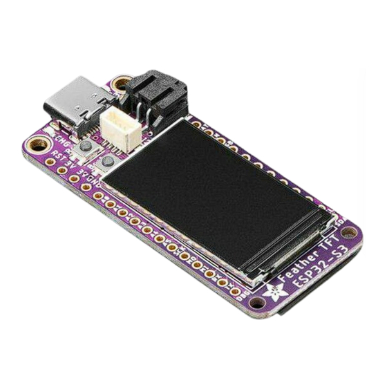
- Page 1 Adafruit ESP32-S3 TFT Feather Created by Kattni Rembor https://learn.adafruit.com/adafruit-esp32-s3-tft-feather Last updated on 2023-03-16 04:05:25 PM EDT ©Adafruit Industries Page 1 of 263...
-
Page 2: Table Of Contents
Table of Contents Overview Pinouts • Power • TFT Display • ESP32-S3 WiFi Module • LC709203 Battery Monitor • BME280 Temperature, Humidity and Pressure Sensor • Logic Pins • NeoPixel and Red LED • STEMMA QT • Buttons • Debug... - Page 3 Entering the REPL • Interacting with the REPL • Returning to the Serial Console CircuitPython Libraries • The Adafruit Learn Guide Project Bundle • The Adafruit CircuitPython Library Bundle • Downloading the Adafruit CircuitPython Library Bundle • The CircuitPython Community Library Bundle •...
- Page 4 • Copy Files on MacOS Without Creating Hidden Files • Other MacOS Space-Saving Tips • Device Locked Up or Boot Looping Welcome to the Community! • Adafruit Discord • CircuitPython.org • Adafruit GitHub • Adafruit Forums • Read the Docs...
- Page 5 NeoPixel Color and Brightness • RGB LED Colors • NeoPixel Rainbow CircuitPython Internet Test • Secrets File Adafruit IO: Send and Receive Data • NeoPixel Location • Adafruit IO Feeds and Dashboard • Adafruit IO Example Secrets • Adafruit IO Example Code •...
- Page 6 • Adafruit IO Setup • Code Usage WipperSnapper Setup • What is WipperSnapper • Sign up for Adafruit.io • Add a New Device to Adafruit IO • Feedback • Troubleshooting • "Uninstalling" WipperSnapper WipperSnapper Usage • Blink a LED •...
- Page 7 Reset the board • Older Versions of Chrome • The Flash an Arduino Sketch Method • Arduino IDE Setup • Load the Blink Sketch Install UF2 Bootloader Downloads • Files • Schematic and Fab Print ©Adafruit Industries Page 7 of 263...
- Page 8 ©Adafruit Industries Page 8 of 263...
-
Page 9: Overview
But we can provide your second-deepest desire: an ESP32-S3 Feather board with a built in IPS TFT color display. It's got all the delicious creamy goodness features of a Feather main board, the comforting warmth of an ESP32-S3 WiFi+BLE microcontroller, and the crispness of a 240x135 pixel color TFT display. - Page 10 Things (IoT) (), wearable electronics (), and smart homes. The BLE implementation in CircuitPython for the ESP32-S3 is still under development and has limitations. Currently, your program can act as a central, and connect to a peripheral. You can advertise, but you cannot create services.
- Page 11 The Feather ESP32-S3 has a dual-core 240 MHz chip, so it is comparable to ESP32's dual-core. However, there is no Bluetooth Classic support, only Bluetooth LE. This chip is a great step up from the earlier ESP32-S2! This ESP32-S3 mini-module we are...
- Page 12 TFT feather uses about 100uA of current. Features: • ESP32-S3 Dual Core 240MHz Tensilica processor - the next generation of ESP32-Sx, with native USB so it can act like a keyboard/mouse, MIDI device, disk drive, etc! •...
-
Page 13: Pinouts
Lipoly connection. Quiescent current is from the power regulator, ESP32-S2 chip, and Lipoly monitor. Turn off the NeoPixel and external I2C/TFT power for the lowest quiescent current draw. • Works with Arduino or CircuitPython Pinouts ©Adafruit Industries Page 13 of 263... -
Page 14: Power
PrettyPins PDF GitHub (). Power ©Adafruit Industries Page 14 of 263... -
Page 15: Tft Display
There are two ways you can power the Feather ESP32-S3, as well as other related pins. • USB-C port - This is used for both powering and programming the board. You can power it with any USB C cable. When USB is plugged in it will charge the LiPoly battery. -
Page 16: Esp32-S3 Wifi Module
Things (IoT) (), wearable electronics (), and smart homes. The Feather ESP32-S3 has a dual-core 240 MHz chip, so it is comparable to ESP32's dual-core. However, there is no Bluetooth Classic support, only Bluetooth LE. This chip is a great step up from the earlier ESP32-S2! This ESP32-S3 mini-module we are using on the Feather comes with 4 MB flash and 2 MB PSRAM, as well as 512KB of... -
Page 17: Lc709203 Battery Monitor
(mAh of the battery, this helps tune the calculation) and read the voltage and percentage whenever you like. There is no pin on the Feather ESP32-S3 that returns battery voltage, but this I2C monitor makes it super simple to get that data! There is a power pin that must be pulled high for the sensor to work. -
Page 18: Bme280 Temperature, Humidity And Pressure Sensor
The ESP32-S3 TFT Feather comes with an unpopulated space for a BME280 Temperature, Humidity and Barometric Pressure Sensor. There is currently no BME280 sensor shipped on the ESP32-S3 TFT Feather - only a space for it! The sensor connects over I2C (at address 0x77), and provides immediate ambient weather sensing. -
Page 19: Logic Pins
UART, I2C or SPI ports to any pin. There are some exceptions..There are six analog pins. • A0 thru A5 can also be analog inputs. A0 thru A4 are on ADC2, and A5 is on ADC1. ©Adafruit Industries Page 19 of 263... - Page 20 The SPI pins are on the ESP32-S3 high-speed peripheral. You can set any pins to be the low-speed peripheral but you won't get the speedy interface! • SCK - This is the SPI clock pin. • MOSI - This is the SPI Microcontroller Out / Sensor In pin.
-
Page 21: Neopixel And Red Led
Red LED - This little red LED, labeled #13 on the board, is on or blinks during certain operations (such as pulsing when in the bootloader), and is controllable in code. It is available in CircuitPython as , and in Arduino as board.LED LED_BUILTIN ©Adafruit Industries Page 21 of 263... -
Page 22: Stemma Qt
If you run into I2C or TFT power issues on Arduino, ensure you are using the latest Espressif board support package. If you are still having issues, you may need to manually pull the pin HIGH in your code. Buttons ©Adafruit Industries Page 22 of 263... -
Page 23: Debug
There are two buttons on the ESP32-S3 TFT Feather. • Reset button - This button restarts the board and helps enter the bootloader. You can click it once to reset the board without unplugging the USB cable or battery. Tap once, and then tap again while the NeoPixel status LED is purple to enter the UF2 bootloader (needed to load CircuitPython). - Page 24 • Light sleep: 2mA assuming all external hardware is de-powered • Deep sleep: 100uA assuming all external hardware is de-powered There are two power pins on the ESP32-S3 TFT Feather: , and TFT_I2C_POWER NEOPIXEL_POWER In CircuitPython and Arduino, both power pins are enabled by default, so if desired, y ou must disable them manually in your code to reach lower power modes.
- Page 25 // not so bright pixel.setPixelColor(0, 0xFFFFFF); pixel.show(); #endif void LEDoff() { #if defined(PIN_NEOPIXEL) pixel.setPixelColor(0, 0x0); pixel.show(); #endif void enableInternalPower() { #if defined(NEOPIXEL_POWER) pinMode(NEOPIXEL_POWER, OUTPUT); digitalWrite(NEOPIXEL_POWER, HIGH); #endif #if defined(NEOPIXEL_I2C_POWER) pinMode(NEOPIXEL_I2C_POWER, OUTPUT); digitalWrite(NEOPIXEL_I2C_POWER, HIGH); #endif #if defined(ARDUINO_ADAFRUIT_FEATHER_ESP32S2) ©Adafruit Industries Page 25 of 263...
- Page 26 1A on all Nordic DKs, in... https://www.adafruit.com/product/5048 When running the above code and monitoring with a PPK, you'll get a graph like this: ©Adafruit Industries Page 26 of 263...
- Page 27 1 second pause at deep sleep. Power Draw for ESP32-S3 TFT Feather The following graphs show the power draw for the ESP32-S3 TFT Feather in normal power mode, light sleep mode, and deep sleep mode. Normal Power Mode The power draw, running normally (without WiFi), is 40mA.
- Page 28 Light Sleep Mode The power draw in light sleep mode is 2mA. Deep Sleep Mode The power draw in deep sleep mode is around 70uA. ©Adafruit Industries Page 28 of 263...
-
Page 29: Power Management
LiPoly connected as a 'backup' power that will only get used when USB power is lost. The JST connector polarity is matched to Adafruit LiPoly batteries. Using wrong polarity batteries can destroy your Feather. ©Adafruit Industries... -
Page 30: Power Supplies
We also have the 3V pin which has the output from the 3.3V regulator. We use a 500mA peak regulator. While you can get 500mA from it, you can't do it continuously from 5V as it will overheat the regulator. ©Adafruit Industries Page 30 of 263... -
Page 31: Measuring Battery
3.2V or so before the protection circuitry cuts it off. By measuring the voltage you can quickly tell when you're heading below 3.7V. On the ESP32-S3 only, there is a problem with the I2C implementation in CircuitPython that causes the LC709203F to be unreadable. This issue is being tracked at https://github.com/adafruit/circuitpython/issues/6311. - Page 32 There is no pin on this board that returns battery voltage, but this I2C monitor makes it super simple to get that data! In Arduino, you can measure the battery voltage using the following script. // SPDX-FileCopyrightText: 2023 Liz Clark for Adafruit Industries // SPDX-License-Identifier: MIT // Adafruit Battery Monitor Demo // Checks for MAX17048 or LC709203F #include <Wire.h>...
- Page 33 Serial.println(" V"); Serial.print(F("Batt Percent: ")); Serial.print(maxlipo.cellPercent(), 1); Serial.println(" %"); Serial.println(); For CircuitPython, you can measure it like this. # SPDX-FileCopyrightText: Copyright (c) 2023 Kattni Rembor for Adafruit Industries # SPDX-License-Identifier: Unlicense import time import board from adafruit_max1704x import MAX17048 from adafruit_lc709203f import LC709203F, PackSize ©Adafruit Industries...
-
Page 34: Enable Pin
If you'd like to turn off the 3.3V regulator, you can do that with the EN(able) pin. Simply tie this pin to Ground and it will disable the 3V regulator. The BAT and USB pins will still be powered. ©Adafruit Industries Page 34 of 263... - Page 35 STEMMA QT and NeoPixel Power The ESP32-S3 TFT Feather is equipped with a STEMMA QT port and NeoPixel which are both connected to their own regulators. Unlike the one controlled by the ENable pin, these two are controlled by GPIO. They are enabled by default in CircuitPython and Arduino.
-
Page 36: Alternative Power Options
Do not use alkaline or NiMH batteries and connect to the battery port - this will destroy the LiPoly charger and there's no way to disable the charger • Do not use 7.4V RC batteries on the battery port - this will destroy the board ©Adafruit Industries Page 36 of 263... -
Page 37: Circuitpython
Follow this step-by-step to quickly get CircuitPython running on your board. Download the latest version of CircuitPython for this board via circuitpython.org Click the link above to download the latest CircuitPython UF2 file. Save it wherever is convenient for you. ©Adafruit Industries Page 37 of 263... - Page 38 A lot of people end up using charge-only USB cables and it is very frustrating! Make sure you have a USB cable you know is good for data sync. ©Adafruit Industries Page 38 of 263...
-
Page 39: Installing The Mu Editor
That's it! Installing the Mu Editor Mu is a simple code editor that works with the Adafruit CircuitPython boards. It's written in Python and works on Windows, MacOS, Linux and Raspberry Pi. The serial console is built right in so you get immediate feedback from your board's serial output! ©Adafruit Industries... -
Page 40: Download And Install Mu
Windows users: due to the nature of MSI installers, please remove old versions of Mu before installing the latest version. Ubuntu users: Mu currently (checked May 4, 2022) does not install properly on Ubuntu 22.04. See https://github.com/mu-editor/mu/issues to track this issue. See https://learn.adafruit.com/welcome-to-circuitpython/recommended-editors and https://learn.adafruit.com/welcome-to-circuitpython/pycharm-and- circuitpython for other editors to use. ©Adafruit Industries... -
Page 41: Starting Up Mu
CIRCUITPY drive is mounted before starting Mu. Using Mu You can now explore Mu! The three main sections of the window are labeled below; the button bar, the text editor, and the serial console / REPL. ©Adafruit Industries Page 41 of 263... -
Page 42: The Circuitpy Drive
Note that all changes to the contents of CIRCUITPY, such as saving a new file, renaming a current file, or deleting an existing file will trigger a reset of the board. ©Adafruit Industries Page 42 of 263... -
Page 43: Boards Without Circuitpy
This section covers how to create and edit your first CircuitPython program. To create and edit code, all you'll need is an editor. There are many options. Adafruit strongly recommends using Mu! It's designed for CircuitPython, and it's really simple and easy to use, with a built in serial console! If you don't or can't use Mu, there are a number of other editors that work quite well. -
Page 44: Creating Code
If you're using a KB2040, QT Py or a Trinkey, please download the NeoPixel blink example (). The NeoPixel blink example uses the onboard NeoPixel, but the time code is the same. You can use the linked NeoPixel Blink example to follow along with this guide page. ©Adafruit Industries Page 44 of 263... - Page 45 On most boards you'll find a tiny red LED. On the ItsyBitsy nRF52840, you'll find a tiny blue LED. On QT Py M0, QT Py RP2040, and the Trinkey series, you will find only an RGB NeoPixel LED. ©Adafruit Industries Page 45 of 263...
-
Page 46: Editing Code
If you are dragging a file from your host computer onto the CIRCUITPY drive, you still need to do step 2. Eject or Sync (below) to make sure the file is completely written. ©Adafruit Industries Page 46 of 263... -
Page 47: Back To Editing Code
Leave the rest of the code as-is. Save your file. See what happens to the LED on your board? Something changed! Do you know why? You don't have to stop there! Let's keep going. Change the second so it looks like this: ©Adafruit Industries Page 47 of 263... -
Page 48: Naming Your Program File
First, you'll take a look at the code you're editing. Here is the original code again: import board import digitalio import time led = digitalio.DigitalInOut(board.LED) led.direction = digitalio.Direction.OUTPUT while True: led.value = True time.sleep(0.5) led.value = False time.sleep(0.5) ©Adafruit Industries Page 48 of 263... -
Page 49: Imports & Libraries
Code will loop "while" the while True: condition is "true" (vs. false), and as is never False, the code will loop forever. True All code that is indented under is "inside" the loop. while True: ©Adafruit Industries Page 49 of 263... -
Page 50: What Happens When My Code Finishes Running
This is because the code finishes running and resets the pin state, and the LED is no longer receiving a signal. To that end, most CircuitPython programs involve some kind of loop, infinite or otherwise. ©Adafruit Industries Page 50 of 263... -
Page 51: What If I Don't Have The Loop
It is also helpful for troubleshooting errors, because your board will send errors and the serial console will display those too. The serial console requires an editor that has a built in terminal, or a separate ©Adafruit Industries Page 51 of 263... -
Page 52: Are You Using Mu
If nothing appears in the serial console, it may mean your code is done running or has no print statements in it. Click into the serial console part of Mu, and press CTRL+D to reload. ©Adafruit Industries Page 52 of 263... -
Page 53: Serial Console Issues Or Delays On Linux
If you're not using Mu to edit, are using or if for some reason you are not a fan of its built in serial console, you can run the serial console from a separate program. ©Adafruit Industries Page 53 of 263... -
Page 54: Interacting With The Serial Console
= digitalio.Direction.OUTPUT while True: print("Hello, CircuitPython!") led.value = True time.sleep(1) led.value = False time.sleep(1) Save your file. Now, let's go take a look at the window with our connection to the serial console. ©Adafruit Industries Page 54 of 263... - Page 55 Delete the at the end of from the line so that it says True led.value = True d.value = Tru import board import digitalio import time ©Adafruit Industries Page 55 of 263...
- Page 56 If you're still unsure, try googling the error to get some help. In this case, you know what to look for. You spelled True wrong. Fix the typo and save your file. ©Adafruit Industries Page 56 of 263...
-
Page 57: The Repl
If there is code running, in this case code measuring distance, it will stop and you'll Follow those Press any key to enter the REPL. Use CTRL-D to reload. instructions, and press any key on your keyboard. ©Adafruit Industries Page 57 of 263... - Page 58 Regardless, once you press a key you'll see a prompt welcoming you to the >>> REPL! If you have trouble getting to the prompt, try pressing Ctrl + C a few more times. >>> ©Adafruit Industries Page 58 of 263...
-
Page 59: Interacting With The Repl
That's exactly what this is talking about! This is a perfect place to start. Let's take a look! Type into the REPL next to the prompt, and press enter. help("modules") ©Adafruit Industries Page 59 of 263... - Page 60 Every programmer in every programming language starts with a piece of code that says, "Hello, World." You're going to say hello to something else. Type into the REPL: print("Hello, CircuitPython!") ©Adafruit Industries Page 60 of 263...
-
Page 61: Returning To The Serial Console
And if your program was affecting anything visual on the board, you'll see that start up again as well. You can return to the REPL at any time! ©Adafruit Industries Page 61 of 263... -
Page 62: Circuitpython Libraries
CircuitPython Libraries As CircuitPython development continues and there are new releases, Adafruit will stop supporting older releases. Visit https://circuitpython.org/downloads to download the latest version of CircuitPython for your board. You must download the CircuitPython Library Bundle that matches your version of CircuitPython. -
Page 63: The Adafruit Learn Guide Project Bundle
The Adafruit Learn Guide Project Bundle The quickest and easiest way to get going with a project from the Adafruit Learn System is by utilising the Project Bundle. Most guides now have a Download Project Bundle button available at the top of the full code example embed. This button downloads all the necessary files, including images, etc., to get the guide project up... - Page 64 In some cases, there will be other files such as audio or images in the same directory as code.py and lib/. Make sure you include all the files when you copy things over! ©Adafruit Industries Page 64 of 263...
-
Page 65: The Adafruit Circuitpython Library Bundle
Library Bundle. The bundle contains all the files needed to use each library. Downloading the Adafruit CircuitPython Library Bundle You can download the latest Adafruit CircuitPython Library Bundle release by clicking the button below. The libraries are being constantly updated and improved, so you'll always want to download the latest bundle. ... -
Page 66: The Circuitpython Community Library Bundle
CircuitPython community. These libraries are often written when community members encountered hardware not supported in the Adafruit Bundle, or to support a personal project. The authors all chose to submit these libraries to the Community Bundle make them available to the community. -
Page 67: Example Files
(as seen above), as well as an examples-only bundle. These are included for two main reasons: • Allow for quick testing of devices. • Provide an example base of code, that is easily built upon for individualized purposes. ©Adafruit Industries Page 67 of 263... -
Page 68: Copying Libraries To Your Board
First up: the best place to start. When you look at most CircuitPython examples, you'll see they begin with one or more statements. These typically look like the following: import • import library_or_module ©Adafruit Industries Page 68 of 263... - Page 69 The following is the list of modules built into CircuitPython for the Feather RP2040. Your list may look similar or be anything down to a significant subset of this list for smaller boards. ©Adafruit Industries Page 69 of 263...
- Page 70 That is how you can use your example code to figure out what libraries to load on your CircuitPython-compatible board! ©Adafruit Industries Page 70 of 263...
-
Page 71: Example: Importerror Due To Missing Library
= simpleio.DigitalOut(board.LED) while True: led.value = True time.sleep(0.5) led.value = False time.sleep(0.5) Save this file. Nothing happens to your board. Let's check the serial console to see what's going on. ©Adafruit Industries Page 71 of 263... -
Page 72: Library Install On Non-Express Boards
You'll find suggestions on the Troubleshooting page (). Updating CircuitPython Libraries and Examples Libraries and examples are updated from time to time, and it's important to update the files you have on your CIRCUITPY drive. ©Adafruit Industries Page 72 of 263... -
Page 73: Circup Cli Tool
CircuitPython core and related topics. It includes API and usage info, a design guide and information about porting CircuitPython to new boards, MicroPython info with relation to CircuitPython, and general information about the project. ©Adafruit Industries Page 73 of 263... - Page 74 The fourth and final section is About the Project. It includes further information including details on building, testing, and debugging CircuitPython, along with various other useful links including the Adafruit Community Code of Conduct. Whether you're a seasoned pro or new to electronics and programming, you'll find a...
-
Page 75: Circuitpython Library Documentation
CircuitPython Library Documentation The Adafruit CircuitPython libraries are documented in a very similar fashion. Each library has its own page on Read the Docs. There is a comprehensive list available e (). Otherwise, to view the documentation for a specific library, you can visit the GitHub repository for the library, and find the link in the README. - Page 76 The LED Animation documentation includes a series of examples, all of which are available in the library. These examples include demonstrations of both basic and more complex features. Simply click on the example that interests you to view the associated code. ©Adafruit Industries Page 76 of 263...
- Page 77 Click on the first item in the list to begin viewing the API Reference section. As with the Examples section, all of the API Reference content is on a single page, and the links under API Reference are anchor links to the specified section of the page. ©Adafruit Industries Page 77 of 263...
- Page 78 You may be interested in something a little more practical. Here is an example. To use the LED Animation library Comet animation, you would run the following example. # SPDX-FileCopyrightText: 2021 Kattni Rembor for Adafruit Industries # SPDX-License-Identifier: MIT """...
- Page 79 This type of information is available for any function you would set up in your code. If you need clarification on something, wonder whether there's more options available, or are simply interested in the details involved in the code you're writing, check out the documentation for the CircuitPython libraries! ©Adafruit Industries Page 79 of 263...
-
Page 80: Recommended Editors
This section is the same for every library. It includes a list of links to external sites, which you can visit for more information about the CircuitPython Project and Adafruit. That covers the CircuitPython library documentation! When you are ready to go... -
Page 81: Recommended Only With Particular Settings Or Add-Ons
You are strongly encouraged to upgrade to Windows 10 if you are still using Windows 7 or Windows 8 or 8.1. Windows 7 has reached end-of-life and no longer receives security updates. A free upgrade to Windows 10 is still available (). ©Adafruit Industries Page 81 of 263... -
Page 82: What's The Com
(COM#) after it where # is a number. Now plug in your board. The Device Manager list will refresh and a new item will appear under Ports (COM & LPT). You'll find a different (COM#) after this item in the list. ©Adafruit Industries Page 82 of 263... -
Page 83: Install Putty
In the box under Speed, enter 115200. This called the baud rate, which is the speed in bits per second that data is sent over the serial connection. For boards with built in USB it doesn't matter so much but for ESP8266 and other board ©Adafruit Industries Page 83 of 263... - Page 84 Enter a name in the box under Saved Sessions, and click the Save button on the right. Once your settings are entered, you're ready to connect to the serial console. Click "Open" at the bottom of the window. A new window will open. ©Adafruit Industries Page 84 of 263...
-
Page 85: Advanced Serial Console On Mac
In this case, you're asking to see all of the listings in that start with /dev/ and end in anything. This will show us the current serial connections. ©Adafruit Industries Page 85 of 263... -
Page 86: Connect With Screen
The baud rate is the speed in bits per second that data is sent over the serial connection. In this case, the speed required by the board is 115200 bits per second. ©Adafruit Industries Page 86 of 263... -
Page 87: Advanced Serial Console On Linux
Each serial connection shows up in the /dev/ directory. It has a name that starts with tt yACM. The command shows you a list of items in a directory. You can use as a wildcard, to search for files that start with the same letters but end in something ©Adafruit Industries Page 87 of 263... -
Page 88: Connect With Screen
Now that you know the name your board is using, you're ready connect to the serial console. You'll use a command called . You may need to install it using the screen package manager. ©Adafruit Industries Page 88 of 263... -
Page 89: Permissions On Linux
Linux keeps track of users and groups and what they are allowed to do and not do, like access the hardware associated with the serial connection for running . So if you see something like this: screen ©Adafruit Industries Page 89 of 263... - Page 90 After you log in again, verify that you have been added to the group using the command . If you are still not in the group, reboot and groups check again. ©Adafruit Industries Page 90 of 263...
-
Page 91: Frequently Asked Questions
These are some of the common questions regarding CircuitPython and CircuitPython microcontrollers. What are some common acronyms to know? CP or CPy = CircuitPython () CPC = Circuit Playground Classic () (does not run CircuitPython) CPX = Circuit Playground Express () CPB = Circuit Playground Bluefruit () ©Adafruit Industries Page 91 of 263... -
Page 92: Using Older Versions
Using Older Versions As CircuitPython development continues and there are new releases, Adafruit will stop supporting older releases. Visit https://circuitpython.org/downloads to download the latest version of CircuitPython for your board. You must download the CircuitPython Library Bundle that matches your version of CircuitPython. -
Page 93: Wireless Connectivity
Boards without long integer support are mostly SAMD21 ("M0") boards without an external flash chip, such as the Adafruit Gemma M0, Trinket M0, QT Py M0, and the Trinkey series. There are also a number of third-party boards in this category. -
Page 94: Asyncio And Interrupts
Are there other ways to communicate by radio with CircuitPython? Check out Adafruit's RFM boards ()for simple radio communication supported by CircuitPython, which can be used over distances of 100m to over a km, depending on the version. The RFM SAMD21 M0 boards can be used, but they were not designed for CircuitPython, and have limited RAM and flash space;... -
Page 95: Memory Issues
It can because the memory gets fragmented differently depending on allocation order and the size of objects. Loading .mpy files uses less memory so its recommended to do that for files you aren't editing. ©Adafruit Industries Page 95 of 263... -
Page 96: Unsupported Hardware
As of CircuitPython 8.x we have started to support ESP32 and ESP32-C3 and have added a WiFi workflow for wireless coding! () We also support ESP32-S2 & ESP32-S3, which have native USB. Does Feather M0 support WINC1500? No, WINC1500 will not fit into the M0 flash space. - Page 97 I have to continue using CircuitPython 5.x or earlier. Where can I find compatible libraries? Adafruit is no longer building or supporting the CircuitPython 5.x or earlier library bundles. You are highly encourged to update CircuitPython to the latest version ()
- Page 98 Windows 10 Did you install the Adafruit Windows Drivers package by mistake, or did you upgrade to Windows 10 with the driver package installed? You don't need to install this package on Windows 10 for most Adafruit boards. The old version (v1.5) can interfere with recognizing your device.
- Page 99 You should now be done! Test by unplugging and replugging the board. You should see the CIRCUITPY drive, and when you double-click the reset button (single click on Circuit Playground Express running MakeCode), you should see the appropriate boar dnameBOOT drive. Let us know in the Adafruit support forums () or on the Adafruit Discord ()
- Page 100 Unplug all the boards and other USB devices you want to clean up. Run the tool as Administrator. You will see a listing like this, probably with many more devices. It is listing all the USB devices that are not currently attached. ©Adafruit Industries Page 100 of 263...
- Page 101 This applies to any kind of serial output whether it be error messages or print statements. So before you start trying to debug your problem on the hardware side, ©Adafruit Industries Page 101 of 263...
- Page 102 The status LED blinks were changed in CircuitPython 7.0.0 in order to save battery power and simplify the blinks. These blink patterns will occur on single color LEDs when the board does not have any RGB LEDs. Speed and blink count also vary for this reason. ©Adafruit Industries Page 102 of 263...
- Page 103 LED color from the REPL. The status indicator will not persist on non-NeoPixel or DotStar LEDs. CircuitPython 6.3.0 and earlier Here's what the colors and blinking mean: • steady GREEN: code.py (or code.txt, main.py, or main.txt) is running ©Adafruit Industries Page 103 of 263...
- Page 104 E flashes are thousands' place, BLUE are hundreds' place, YELLOW are tens' place, and CYAN are one's place. So for example, an error on line 32 would flash YELLOW three times and then CYAN two times. Zeroes are indicated by an extra-long dark gap. ©Adafruit Industries Page 104 of 263...
- Page 105 Whether you've run into a situation where you can no longer edit your code.py on your CIRCUITPY drive, your board has gotten into a state where CIRCUITPY is read- only, or you have turned off the CIRCUITPY drive altogether, safe mode can help. ©Adafruit Industries Page 105 of 263...
- Page 106 Once you've entered safe mode successfully in CircuitPython 6.x, the LED will pulse yellow. If you successfully enter safe mode on CircuitPython 7.x, the LED will intermittently blink yellow three times. If you connect to the serial console, you'll find the following message. ©Adafruit Industries Page 106 of 263...
- Page 107 Erase CIRCUITPY Without Access to the REPL If you can't access the REPL, or you're running a version of CircuitPython previous to 2.3.0 and you don't want to upgrade, there are options available for some specific boards. ©Adafruit Industries Page 107 of 263...
- Page 108 Feather M4 Express Metro M0 Express Metro M4 Express QSPI Eraser Trellis M4 Express (QSPI) Grand Central M4 Express (QSPI) PyPortal M4 Express (QSPI) Circuit Playground Bluefruit (QSPI) Monster M4SK (QSPI) PyBadge/PyGamer QSPI Eraser.UF2 ©Adafruit Industries Page 108 of 263...
- Page 109 Trinket M0, GEMMA M0, QT Py M0, and the SAMD21-based Trinkey boards. If you are trying to erase a SAMD21 non-Express board, follow these steps to erase your board. 1. Download the erase file: SAMD21 non-Express Boards ©Adafruit Industries Page 109 of 263...
- Page 110 The file system on the board is very tiny. (Smaller than an ancient floppy disk.) So, its likely you'll run out of space but don't panic! There are a number of ways to free up space. ©Adafruit Industries Page 110 of 263...
- Page 111 Prevent & Remove MacOS Hidden Files First find the volume name for your board. With the board plugged in run this command in a terminal to list all the volumes: ls -l /Volumes ©Adafruit Industries Page 111 of 263...
- Page 112 Finder because it will still create these hidden extended attribute files in some cases (for files downloaded from the internet, like Adafruit's modules). To copy a file or folder use the -X option for the cp command in a terminal. For example to copy a file_name.mpy file to the board use a command like:...
- Page 113 Finder to do this, you must do it via command line! There are a few of the hidden files that MacOS loves to generate, all of which begin with a ._ before the file name. Remove the ._ files using the command. You can ©Adafruit Industries Page 113 of 263...
- Page 114 Since your reaction time may not be that fast, try a "slow" double click, to catch the yellow LED on the second click. For ESP32-S2 based devices: Press and release the reset button, then press and release the boot button about 3/4 of a second later. ©Adafruit Industries Page 114 of 263...
- Page 115 Whether this is your first microcontroller board or you're a seasoned software engineer, you have something important to offer the Adafruit CircuitPython community. This page highlights some of the many ways you can be a part of it! ©Adafruit Industries...
- Page 116 Adafruit Discord The Adafruit Discord server is the best place to start. Discord is where the community comes together to volunteer and provide live support of all kinds. From general discussion to detailed problem solving, and everything in between, Discord is a digital maker space with makers from around the world.
- Page 117 CircuitPython.org Beyond the Adafruit Learn System, which you are viewing right now, the best place to find information about CircuitPython is circuitpython.org (). Everything you need to get started with your new microcontroller and beyond is available. You can do things like download CircuitPython for your microcontroller ()
- Page 118 GitHub pull requests, or PRs, are opened when folks have added something to an Adafruit CircuitPython library GitHub repo, and are asking for Adafruit to add, or merge, their changes into the main library code. For PRs to be merged, they must first be reviewed.
- Page 119 If you're looking for something a little more complicated, consider "Bug" or "Enhancement". The Bug label is applied to issues that pertain to problems or failures found in the library. The Enhancement label is applied to feature requests. ©Adafruit Industries Page 119 of 263...
- Page 120 CircuitPython core. It means that folks who do not speak English have the opportunity to have these messages shown to them in their own language when using CircuitPython. This is ©Adafruit Industries Page 120 of 263...
- Page 121 Adafruit GitHub Whether you're just beginning or are life-long programmer who would like to contribute, there are ways for everyone to be a part of the CircuitPython project. The CircuitPython core is written in C. The libraries are written in Python. GitHub is the...
- Page 122 You need an Adafruit account to post to the forums. You can use the same account you use to order from Adafruit.
- Page 123 There are forum categories that cover all kinds of topics, including everything Adafruit. The Adafruit CircuitPython () category under "Supported Products & Projects" is the best place to post your CircuitPython questions. Be sure to include the steps you took to get to where you are. If it involves wiring,...
- Page 124 Some examples require external components, such as switches or sensors. You'll find wiring diagrams where applicable to show you how to wire up the necessary components to work with each example. The following components are needed to complete all of the examples: ©Adafruit Industries Page 124 of 263...
- Page 125 ±0.25°C over the sensor's -40°C to... https://www.adafruit.com/product/5027 Adafruit Mono 2.5W Class D Audio Amplifier - PAM8302 This super small mono amplifier is surprisingly powerful - able to deliver up to 2.5 Watts into 4-8 ohm impedance...
- Page 126 Adafruit I2S Stereo Decoder - UDA1334A Breakout Discontinued - you can grab Adafruit I2S 3W Class D Amplifier Breakout - MAX98357A instead! This fully-featured... https://www.adafruit.com/product/3678 Premium Male/Male Jumper Wires - 20 x 6" (150mm) These Male/Male Jumper Wires are handy for making wire harnesses or jumpering between headers on PCB's.
- Page 127 CircuitPython you're using and copy the contents of that directory to your CIRCUITPY drive. Your CIRCUITPY drive should now look similar to the following image: # SPDX-FileCopyrightText: 2021 Kattni Rembor for Adafruit Industries # SPDX-License-Identifier: MIT """CircuitPython Blink Example - the CircuitPython 'Hello, World!'"""...
- Page 128 LED as a digital output. You can just as easily set up a digital input such as a button to control the LED. This example builds on the basic Blink ©Adafruit Industries Page 128 of 263...
- Page 129 CircuitPython you're using and copy the contents of that directory to your CIRCUITPY drive. Your CIRCUITPY drive should now look similar to the following image: # SPDX-FileCopyrightText: 2022 Kattni Rembor for Adafruit Industries # SPDX-License-Identifier: MIT """...
- Page 130 . Then, you tell the pin to act as an OUTPUT You include setup for the button as well. It is similar to the LED setup, except the button is an , and requires a pull up. INPUT ©Adafruit Industries Page 130 of 263...
- Page 131 1.8V, 1.81V, 1.801V, 1.8001V, 1.80001V and so forth to infinity. Many devices use analog signals, in particular sensors typically output an analog signal or voltage that varies based on something being sensed like light, heat, humidity, etc. ©Adafruit Industries Page 131 of 263...
- Page 132 By wiring the potentiometer to your board in a special way (called a voltage divider) you can turn the change in resistance into a change in voltage that your board’s analog to digital converter can read. ©Adafruit Industries Page 132 of 263...
- Page 133 Connect the other outside pin to voltage in (e.g. 3.3V) Connect the middle pin to an analog pin (e.g. A0) Hardware In addition to your microcontroller board, you will need the following hardware to follow along with this example. Potentiometer ©Adafruit Industries Page 133 of 263...
- Page 134 CircuitPython_Templates/analog_pin_values/ and then click on the directory that matches the version of CircuitPython you're using and copy the contents of that directory to your CIRCUITPY drive. Your CIRCUITPY drive should now look similar to the following image: ©Adafruit Industries Page 134 of 263...
- Page 135 When you twist it to the right, the value gets bigger up to some value that is dependent on the microcontroller. Many microcontrollers get a value very close to 65535. Some, such as the ESP32-S3, have a smaller limit of about 61000 or 3.1 volts. The code is simple. You begin by importing three modules:...
- Page 136 CircuitPython you're using and copy the contents of that directory to your CIRCUITPY drive. Your CIRCUITPY drive should now look similar to the following image: # SPDX-FileCopyrightText: 2022 Kattni Rembor for Adafruit Industries # SPDX-License-Identifier: MIT """...
- Page 137 Your board has a built-in RGB NeoPixel status LED. You can use CircuitPython code to control the color and brightness of this LED. It is also used to indicate the bootloader status and errors in your CircuitPython code. ©Adafruit Industries Page 137 of 263...
- Page 138 A NeoPixel is what Adafruit calls the WS281x family of addressable RGB LEDs. It contains three LEDs - a red one, a green one and a blue one - along side a driver chip in a tiny package controlled by a single pin. They can be used individually (as in the built-in LED on your board), or chained together in strips or other creative form factors.
- Page 139 # SPDX-FileCopyrightText: 2021 Kattni Rembor for Adafruit Industries # SPDX-License-Identifier: MIT """CircuitPython status NeoPixel red, green, blue example.""" import time import board import neopixel pixel = neopixel.NeoPixel(board.NEOPIXEL, 1) pixel.brightness = 0.3 while True: pixel.fill((255, 0, 0)) time.sleep(0.5) pixel.fill((0, 255, 0)) time.sleep(0.5)
- Page 140 , which has the maximum level of red, and (255, 0, 0) no green or blue. Green would be , etc. For the colors between, you (0, 255, 0) ©Adafruit Industries Page 140 of 263...
- Page 141 CircuitPython you're using and copy the contents of that directory to your CIRCUITPY drive. Your CIRCUITPY drive should now look similar to the following image: # SPDX-FileCopyrightText: 2021 Kattni Rembor for Adafruit Industries # SPDX-License-Identifier: MIT """CircuitPython status NeoPixel rainbow example."""...
- Page 142 , the slower the rainbow will cycle. The helper cycles through the values of the delay color wheel to create a rainbow of colors. Inside the loop, you call the rainbow helper with a 0.2 second delay, by including nbow(0.2) ©Adafruit Industries Page 142 of 263...
- Page 143 Project Bundle button below to download the necessary libraries and the code.py file in a zip file. Extract the contents of the zip file, and copy the entire lib folder and the code.py file to your CIRCUITPY drive. # SPDX-FileCopyrightText: 2020 Brent Rubell for Adafruit Industries # SPDX-License-Identifier: MIT import ipaddress...
- Page 144 The initial secrets.py file on your CIRCUITPY drive should look like this: # SPDX-FileCopyrightText: 2020 Adafruit Industries # SPDX-License-Identifier: Unlicense # This file is where you keep secret settings, passwords, and tokens!
- Page 145 Of course, don't share your secrets.py - keep that out of GitHub, Discord or other project-sharing sites. Don't share your secrets.py file, it has your passwords and API keys in it! If you connect to the serial console, you should see something like the following: ©Adafruit Industries Page 145 of 263...
-
Page 146: Print("My Mac Addr:", [Hex(I) For I In Wifi.radio.mac_Address])
Connects to the access point you defined in the secrets.py file, prints out its local IP address, and attempts to ping google.com to check its network connectivity. print("Connecting to %s"%secrets["ssid"]) wifi.radio.connect(secrets["ssid"], secrets["password"]) print(print("Connected to %s!"%secrets["ssid"])) print("My IP address is", wifi.radio.ipv4_address) ipv4 = ipaddress.ip_address("8.8.4.4") print("Ping google.com: %f ms" % wifi.radio.ping(ipv4)) ©Adafruit Industries Page 146 of 263... - Page 147 USB power or a battery, and still be able to see the data. It also allows you to send data to your microcontroller, such as NeoPixel colors. This example shows how to both send data to and receive data from Adafruit IO. It pulls ©Adafruit Industries...
- Page 148 "random" number generator and sends the "random" number to Adafruit IO, while simultaneously listening for NeoPixel color data from Adafruit IO. NeoPixel Location The NeoPixel LED (highlighted in green), labeled Neo on the silk, is located near the top left corner of the Feather.
- Page 149 Once you choose the color picker block, you'll need to connect a feed to it. Check the box next to neopixel. ©Adafruit Industries Page 149 of 263...
- Page 150 Finally, a Block Settings page will come up. You can add an optional block title here. Then you press Create Block. The dashboard should look something like the following. Now that things are set up on the Adafruit IO end, you can continue on to the code on your microcontroller! ©Adafruit Industries...
-
Page 151: Print("Connected To %S!"%Secrets["Ssid"])
Adafruit IO Example Code To run this example, you need to first install the NeoPixel, Adafruit IO, and Adafruit MiniMQTT libraries into the lib folder on your CIRCUITPY drive. Then you need to update code.py with the example script. - Page 152 Adafruit IO...") io.connect() # Explicitly pump the message loop. io.loop() # Obtain the "random" value, print it and publish it to Adafruit IO every 10 seconds. if (time.monotonic() - timestamp) >= 10: random_number = "{}".format(randint(0, 255)) print("Current 'random' number: {}".format(random_number)) io.publish("random", random_number)
-
Page 153: Print("My Ip Address Is", Wifi.radio.ipv4_Address)
NeoPixel Color Change To change the color of the NeoPixel, go to the NeoPixel Adafruit IO dashboard you created at the beginning, and click on the colored circle in the ColorPicker block. It will bring up the following. - Page 154 These are included where the except code is likely to fail due to WiFi or Adafruit IO connection failures. WiFi can be finicky, and without these code blocks, if the connection was lost, the code would crash. Instead, it is designed to reset the board and start the code over again to reestablish the connection, regardless of the cause.
-
Page 155: Print("Fetching Text From", Text_Url)
ImportError: print("WiFi and Adafruit IO credentials are kept in secrets.py - please add them there!") raise Note that if a secrets.py file is not present on your CIRCUITPY drive, the code will fail to run, and you will receive an error in the serial console. Add a secrets.py file to your CIRCUITPY drive to resolve this error. - Page 156 If the MQTT broker connection is not successful, the error is printed to the serial console, and the board will hard reset after 30 seconds. except Exception as e: print("Failed to connect to Adafruit IO. Error:", e, "\nBoard will hard reset in 30 seconds.") time.sleep(30) microcontroller.reset()
- Page 157 'random' number: {}".format(random_number)) io.publish("random", random_number) timestamp = time.monotonic() If at any time WiFi or Adafruit IO disconnects, the code will print the error to the serial console, and the board will hard reset after 30 seconds. [...] except Exception as e: print("Failed to get or send data, or connect.
- Page 158 This means you can have many different sensors and devices all connected to the same two pins. Both I2C connections require pull-up resistors, and most Adafruit I2C sensors and breakouts have pull-up resistors built in. If you're using one that does not, you'll need to add your own 2.2-10kΩ...
- Page 159 The first thing you'll want to do after getting the sensor wired up, is make sure it's wired correctly. You're going to do an I2C scan to see if the board is detected, and if it is, print out its I2C address. ©Adafruit Industries Page 159 of 263...
- Page 160 The ESP32-S3 TFT Feather comes with one I2C sensor built in. The I2C scan code will show the addresses from the built in sensor and the MCP9808.
- Page 161 Click the Download Project Bundle button below to download the necessary libraries and the code.py file in a zip file. Extract the contents of the zip file, find your CircuitPython version, and copy the matching entire lib folder and code.py file to your CIRCUITPY drive. ©Adafruit Industries Page 161 of 263...
- Page 162 {:.2f} C {:.2f} F ".format(temperature_celsius, temperature_fahrenheit)) time.sleep(2) For the ESP32-S3 TFT Feather, you'll need to change the I2C setup to the commented out setup included in the code above. The ESP32-S3 TFT Feather STEMMA QT connector is available on board.STEMMA_I2...
- Page 163 CircuitPython version, and copy the matching code.py file to your CIRCUITPY drive. Your CIRCUITPY drive should now look similar to the following image: # SPDX-FileCopyrightText: 2021 Kattni Rembor for Adafruit Industries # SPDX-License-Identifier: MIT """CircuitPython I2C possible pin-pair identifying script"""...
- Page 164 Now, connect to the serial console and check out the output! The results print out a nice handy list of SCL and SDA pin pairs that support I2C. The output for the ESP32-S3 TFT Feather is extremely long! The screenshot shows only the beginning. Run the script yourself to see the full output ©Adafruit Industries...
- Page 165 CircuitPython doesn't allow it! Wiring for MCP9808 You're going to be logging the temperature. For this task, you will need to wire up a temperature sensor, like the MCP9808. Connect it to your microcontroller as shown below. ©Adafruit Industries Page 165 of 263...
- Page 166 The boot.py File The filesystem will NOT automatically be set to read-only on creation of this file! You'll still be able to edit files on CIRCUITPY after saving this boot.py. # SPDX-FileCopyrightText: 2021 Kattni Rembor for Adafruit Industries # SPDX-License-Identifier: MIT """...
- Page 167 CircuitPython you're using and copy the contents of that directory to your CIRCUITPY drive. Your CIRCUITPY drive should now look similar to the following image: # SPDX-FileCopyrightText: 2022 Kattni Rembor for Adafruit Industries # SPDX-License-Identifier: MIT """...
- Page 168 0.15 seconds. Inside the loop, the LED is turned on for delay the duration of the , and turned off for the duration of the , effectively delay delay blinking the LED at the speed of the delay ©Adafruit Industries Page 168 of 263...
- Page 169 For the ESP32-S3 TFT Feather, the button-press timing is a little different. Press it when the NeoPixel LED turns white! For the ESP32-S3 TFT Feather, it's difficult to get the timing right for when to press the boot button. So, the boot.py file includes turning the NeoPixel on bright white for one second.
- Page 170 You'll touchio learn how to setup the pin in your program, and read the touch status. Then, you'll learn how to read touches on multiple pins in a single example. Time to get started! ©Adafruit Industries Page 170 of 263...
- Page 171 Your CIRCUITPY drive should now look similar to the following image: Then, connect to the serial console (). # SPDX-FileCopyrightText: 2021 Kattni Rembor for Adafruit Industries # SPDX-License-Identifier: MIT """ CircuitPython Capacitive Touch Pin Example - Print to the serial console when one ©Adafruit Industries...
- Page 172 That's all there is to reading touch on a single pin using in CircuitPython! touchio Multiple Capacitive Touch Pins The next example shows you how to read touches on multiple pins in a single program. ©Adafruit Industries Page 172 of 263...
- Page 173 Your CIRCUITPY drive should now look similar to the following image: Then, connect to the serial console (). # SPDX-FileCopyrightText: 2021 Kattni Rembor for Adafruit Industries # SPDX-License-Identifier: MIT """ CircuitPython Capacitive Two Touch Pin Example - Print to the serial console when a pin is touched.
- Page 174 A4 - CircuitPython: . Arduino: board.A4 • A5 - CircuitPython: . Arduino: board.A5 • D13 - CircuitPython: . Arduino: board.D13 • D12 - CircuitPython: . Arduino: board.D12 • D11 - CircuitPython: . Arduino: board.D11 ©Adafruit Industries Page 174 of 263...
- Page 175 In this section, you'll learn how to use CircuitPython to play different types of audio using I2S, including tones and WAV files. Necessary Hardware You'll need the following additional hardware to complete the examples on this page. ©Adafruit Industries Page 175 of 263...
- Page 176 Adafruit I2S 3W Class D Amplifier Breakout - MAX98357A Listen to this good news - we now have an all in one digital audio amp breakout board that works incredibly well with the https://www.adafruit.com/product/3006 Mono Enclosed Speaker with Plain Wires - 3W 4 Ohm Listen up! This single ...
- Page 177 CircuitPython version, and copy the code.py file to your CIRCUITPY drive. Your CIRCUITPY drive should now look similar to the following image: # SPDX-FileCopyrightText: 2021 Kattni Rembor for Adafruit Industries # SPDX-License-Identifier: MIT """ CircuitPython I2S Tone playback example.
- Page 178 Extract the contents of the zip file, open the folder that matches your CircuitPython version, and copy the StreetChicken.wav file and the code.py file to your CIRCUITPY drive. Your CIRCUITPY drive should now look similar to the following image: ©Adafruit Industries Page 178 of 263...
- Page 179 # SPDX-FileCopyrightText: 2021 Kattni Rembor for Adafruit Industries # SPDX-License-Identifier: MIT """ CircuitPython I2S WAV file playback. Plays a WAV file once. """ import audiocore import board import audiobusio audio = audiobusio.I2SOut(board.A0, board.A1, board.A2) with open("StreetChicken.wav", "rb") as wave_file: wav = audiocore.WaveFile(wave_file) print("Playing wav file!")
- Page 180 This file runs only once, so if you do not see anything in the output, press CTRL+D to reload and run the code again. # SPDX-FileCopyrightText: 2021 Kattni Rembor for Adafruit Industries # SPDX-License-Identifier: MIT """...
- Page 181 This diagram shows the scheduler, running an event loop, with three tasks: Task 1 is running, Task 2 is ready to run, and is waiting for Task 1 to give up control, and Task 3 is waiting for something else, and isn't ready to run yet. ©Adafruit Industries Page 181 of 263...
- Page 182 NeoPixel ring one: data in (DIN) to microcontroller A1 • NeoPixel ring one: ground to microcontroller GND • NeoPixel ring one: V+ to microcontroller 3V • NeoPixel ring two: data in (DIN) to microcontroller A2 ©Adafruit Industries Page 182 of 263...
- Page 183 Extract the contents of the zip file, and copy the entire lib folder and the c ode.py file to your CIRCUITPY drive. # SPDX-FileCopyrightText: Copyright (c) 2022 Dan Halbert for Adafruit Industries # SPDX-FileCopyrightText: Copyright (c) 2022 Kattni Rembor for Adafruit Industries # SPDX-License-Identifier: MIT """...
- Page 184 Your CIRCUITPY drive contents should resemble the image below. You should have at least the following file in the top level of the CIRCUITPY drive: • code.py Your CIRCUITPY/lib folder should contain at least the following folder and files: • asyncio/ ©Adafruit Industries Page 184 of 263...
- Page 185 Now release the button. The rainbow swirl on ring one returns to its original direction, and the blinking on ring two returns to its original speed! Code Walkthrough First you import the necessary modules and libraries. import asyncio import board import neopixel import keypad from rainbowio import colorwheel ©Adafruit Industries Page 185 of 263...
- Page 186 The second function is the blink animation code. This is typical. You fill all the NeoPixel LEDs blue, delay for a specified amount of time, then turn all of the LEDs off, and delay for the same specified amount of time. ©Adafruit Industries Page 186 of 263...
- Page 187 , first create a task. For the , instantiate the main() button_task monitor_butto coroutine by calling it with the arguments desired, and then pass that coroutine wraps the coroutine in a task, and asyncio.create_task() create_task() ©Adafruit Industries Page 187 of 263...
- Page 188 If you want to ensure the task executes forever, have a loop in your task function (e.g. loop). while True The following example is greatly oversimplified, but demonstrates what including a loop in your task function might look like. async def never_ending_task(): while True: print("I'm looping!") await asyncio.sleep(0) ©Adafruit Industries Page 188 of 263...
- Page 189 After you have downloaded and installed the latest version of Arduino IDE, you will need to start the IDE and navigate to the Preferences menu. You can access it from the File menu in Windows or Linux, or the Arduino menu on OS X. A dialog will pop up just like the one shown below. ©Adafruit Industries Page 189 of 263...
- Page 190 URLs is comma separated, and you will only have to add each URL once. New Adafruit boards and updates to existing boards will automatically be picked up by the Board Manager each time it is opened. The URLs point to index files that the Board Manager uses to build the list of available &...
- Page 191 If you have multiple boards you want to support, say ESP8266 and Adafruit, have both URLs in the text box separated by a comma (,) Once done click OK to save the new preference settings. The next step is to actually install the Board Support Package (BSP). Go to the Tools →...
- Page 192 Select ESP32-S2/S3 Board in Arduino IDE On the Arduino IDE, click: Tools -> Board -> ESP32 Arduino -> Your Adafruit ESP32-S2/S3 board The screenshot shows Metro S2 but you may have a different board. Make sure the name matches the exact product you purchased.
- Page 193 Now open up this Blink example in a new sketch window // the setup function runs once when you press reset or power the board void setup() { // initialize built in LED pin as an output. pinMode(LED_BUILTIN, OUTPUT); ©Adafruit Industries Page 193 of 263...
- Page 194 You can now select the new serial port name which will be different than the bootloader serial port. Arduino IDE will try to use auto-reset to automatically put the board into bootloader mode when you ask it to upload new code ©Adafruit Industries Page 194 of 263...
- Page 195 If you haven't yet, check the previous steps in the guide to make sure you: • Install the very latest Arduino IDE for Desktop (not all boards are supported by the Web IDE so we don't recommend it). ©Adafruit Industries Page 195 of 263...
- Page 196 Connect the board to your computer. If your board has a power LED, make sure its lit. Is there a power switch? Make sure its turned On! The ESP32-S3 TFT Feather does not have a power LED or a power switch. No special drivers are required to connect to this board! Start up Arduino IDE and Select Board/Port OK now you are prepared! Open the Arduino IDE on your computer.
- Page 197 New Blink Sketch OK lets make a new blink sketch! From the File menu, select New Then in the new window, copy and paste this text: int led = LED_BUILTIN; void setup() { ©Adafruit Industries Page 197 of 263...
- Page 198 Note that Verifying a sketch is the same as Compiling a sketch - so we will use the words interchangeably During verification/compilation, the computer will do a bunch of work to collect all the libraries and code and the results will appear in the bottom window of the IDE. ©Adafruit Industries Page 198 of 263...
- Page 199 Turning on detailed compilation warnings and output can be very helpful sometimes - Its in Preferences under "Show Verbose Output During:" and check the Compilation button. If you ever need to get help from others, be sure to do ©Adafruit Industries Page 199 of 263...
- Page 200 This is actually one of the hardest parts for beginners because it's where a lot of things can go wrong. However, lets start with what it looks like on success! Here's what your board upload process looks like when it goes right: ©Adafruit Industries Page 200 of 263...
- Page 201 USB interface. It's all in one! Great for cost savings, simplicity of design, reduced size and more control. However, it means the chip must be self-aware enough to be able to put itself into bootload/upload mode on its own. That's fine 99% of the time but is ©Adafruit Industries Page 201 of 263...
- Page 202 Once you are in manual bootload mode, go to the Tools menu, and make sure you have selected the bootloader serial port. It is almost certain that the serial port has changed now that the bootloader is enabled ©Adafruit Industries Page 202 of 263...
- Page 203 OK it was a journey but now we're here and you can enjoy your blinking LED. Next up, try to change the delay between blinks and re-upload. It's a good way to make sure your upload process is smooth and practiced. ©Adafruit Industries Page 203 of 263...
- Page 204 (Only exception is if you're using a hot-plug assistant but that'll cost you ()). • Are you keeping the total bus length reasonable? I2C was designed for maybe 6" max length. We like to push that with plug-n-play cables, but really please ©Adafruit Industries Page 204 of 263...
- Page 205 (Only exception is if you're using an active bus extender ()). The ESP32-S3 Feather has an I2C device built in - the LC709203 battery monitor at address 0x0B. It also has a STEMMA QT connector that shares SCL/SDA with the associated pins available as through-hole pads along the top edge of the board.
- Page 206 { Serial.begin(115200); // Wait for Serial port to open while (!Serial) { delay(10); delay(500); Serial.println("Adafruit I2C Scanner"); #if defined(ARDUINO_ADAFRUIT_QTPY_ESP32S2) || \ defined(ARDUINO_ADAFRUIT_QTPY_ESP32S3_NOPSRAM) || \ defined(ARDUINO_ADAFRUIT_QTPY_ESP32S3) || \ defined(ARDUINO_ADAFRUIT_QTPY_ESP32_PICO) // ESP32 is kinda odd in that secondary ports must be manually // assigned their pins with setPins()! Wire1.setPins(SDA1, SCL1);...
- Page 207 The first thing you'll want to do is get the sensor connected so your board has I2C to talk to. Adafruit MCP9808 High Accuracy I2C Temperature Sensor Breakout The MCP9808 digital temperature sensor is one of the more accurate/precise we've ever seen, with a typical accuracy of ±0.25°C over the sensor's -40°C to...
- Page 208 The LC709203 is available over I2C. The sensor comes with its own Adafruit CircuitPython library that makes it simple to write code to read data from it. This example will be using, among other things, the dafruit LC709203F ()
- Page 209 Arduino Library Installation You can install the necessary libraries from the Library Manager. To open, click Sketch > Include Library > Manage Libraries... Search for LC709203F, and install the Adafruit LC709203F library. When asked about installing dependencies, click Install all. ©Adafruit Industries...
- Page 210 LC709203 Simple Data Example Click File > Examples > Adafruit LC709203F > LC709203F_demo to open the example. #include "Adafruit_LC709203F.h" Adafruit_LC709203F lc; void setup() { Serial.begin(115200); delay(10); Serial.println("\nAdafruit LC709203F demo"); // For the Feather ESP32-S2, we need to enable I2C power first!
- Page 211 Thanksfully if you have ESP32 sketches, they'll 'just work' with variations of ESP32. You can find a wide range of examples in the File->Examples->Examples for Adafruit Metro ESP32-S2 subheading (the name of the board may vary so it could be "Example s for Adafruit Feather ESP32 V2"...
- Page 212 If you can not scan any networks, check your power supply. You need a solid power supply in order for the ESP32 to not brown out. A skinny USB cable or drained battery can cause issues. ©Adafruit Industries Page 212 of 263...
- Page 213 WiFi Connection Test Now that you can scan networks around you, its time to connect to the Internet! Copy the example below and paste it into the Arduino IDE: // SPDX-FileCopyrightText: 2020 Brent Rubell for Adafruit Industries // SPDX-License-Identifier: MIT Web client This sketch connects to a website (wifitest.adafruit.com/testwifi/index.html)
- Page 214 // print the received signal strength: long rssi = WiFi.RSSI(); Serial.print("signal strength (RSSI):"); Serial.print(rssi); Serial.println(" dBm"); NOTE: You must change the in the example code SECRET_SSID SECRET_PASS to your WiFi SSID and password before uploading this to your board. ©Adafruit Industries Page 214 of 263...
- Page 215 WiFi connection to connect to the Twitter API. Copy and paste it into the Arduino IDE: // SPDX-FileCopyrightText: 2015 Arturo Guadalupi // SPDX-FileCopyrightText: 2020 Brent Rubell for Adafruit Industries // SPDX-License-Identifier: MIT This example creates a client object that connects and transfers data using always SSL.
- Page 216 // if you get a connection, report back via serial: if (client.connect(SERVER, 443)) { Serial.println("connected to server"); // Make a HTTP request: client.println("GET " PATH " HTTP/1.1"); client.println("Host: " SERVER); client.println("Connection: close"); client.println(); uint32_t bytes = 0; void loop() { ©Adafruit Industries Page 216 of 263...
- Page 217 As before, update the ssid and password first, then upload the example to your board. Note we use instead of WiFiClientSecure client WiFiClient client; require a SSL connection! This example will connect to a twitter server to download a JSON snippet that says how many followers adafruit has ©Adafruit Industries Page 217 of 263...
- Page 218 Arduino IDE. // SPDX-FileCopyrightText: 2014 Benoit Blanchon // SPDX-FileCopyrightText: 2014 Arturo Guadalupi // SPDX-FileCopyrightText: 2020 Brent Rubell for Adafruit Industries // SPDX-License-Identifier: MIT This example creates a client object that connects and transfers data using always SSL, then shows how to parse a JSON document in an HTTP response.
-
Page 219: If Defined(Arduino_Adafruit_Qtpy_Esp32S2)
0x3C)) { // Address 0x3C for 128x32 Serial.println(F("SSD1306 allocation failed")); for(;;); // Don't proceed, loop forever display.display(); display.setTextSize(1); display.setTextColor(WHITE); display.clearDisplay(); display.setCursor(0,0); #else // Don't wait for serial if we have an OLED while (!Serial) { ©Adafruit Industries Page 219 of 263... - Page 220 (strcmp(status, "HTTP/1.1 200 OK") != 0) { Serial.print(F("Unexpected response: ")); Serial.println(status); #if defined(USE_OLED) display.print("Connection failed, code: "); display.println(status); display.display(); #endif return; // wait until we get a double blank line client.find("\r\n\r\n", 4); ©Adafruit Industries Page 220 of 263...
-
Page 221: Defined(Arduino_Adafruit_Qtpy_Esp32S3)
// assigned their pins with setPins()! Wire1.setPins(SDA1, SCL1); #endif #if defined(NEOPIXEL_I2C_POWER) pinMode(NEOPIXEL_I2C_POWER, OUTPUT); digitalWrite(NEOPIXEL_I2C_POWER, HIGH); // on #endif #if defined(ARDUINO_ADAFRUIT_FEATHER_ESP32S2) // turn on the I2C power by setting pin to opposite of 'rest state' ©Adafruit Industries Page 221 of 263... -
Page 222: Pinmode(Pin_I2C_Power, Input)
The ESP32-S2/S3 is an affordable, all-in-one, option for connecting your projects to the internet using our IoT platform, Adafruit IO (). • For more information and guides about Adafruit IO, check out the Adafruit IO Basics Series. () ©Adafruit Industries Page 222 of 263... - Page 223 Install Libraries In the Arduino IDE, navigate to Sketch -> Include Library->Manage Libraries... Enter Adafruit IO Arduino into the search box, and click Install on the Adafruit IO Arduino library option to install version 4.0.0 or higher. When asked to install dependencies, click Install all. ©Adafruit Industries...
- Page 224 Adafruit IO Setup If you do not already have an Adafruit IO account, create one now (). Next, navigate to the Adafruit IO Dashboards page. We'll create a dashboard to visualize and interact with the data being sent between your ESP32-S2/S3 board and Adafruit IO. ...
- Page 225 We'll want to turn the board's LED on or off from Adafruit IO. To do this, we'll need to add a toggle button to our dashboard. Click the cog at the top right hand corner of your dashboard. In the dashboard settings dropdown, click Create New Block.
- Page 226 Change Button Off Text to 0 Click Create block Next up, we'll want to display button press data from your board on Adafruit IO. To do this, we'll add a gauge block to the Adafruit IO dashboard. A gauge is a read only block type that shows a fixed range of values.
- Page 227 In the dashboard settings dropdown, click Create New Block. Select the gauge block. Under My Feeds, enter button as a feed name. Click Create. Choose the button feed to connect it to the toggle block. Click Next step. ©Adafruit Industries Page 227 of 263...
- Page 228 Code Usage For this example, you will need to open the adafruitio_26_led_btn example included with the Adafruit IO Arduino library. In the Arduino IDE, navigate to File -> Examples -> Adafruit IO Arduino -> adafruitio_26_led_btn. Before uploading this code to the ESP32-S2/S3, you'll need to add your network and Adafruit IO credentials.
- Page 229 Click the Upload button to upload your sketch to the ESP32-S2/S3. After uploading, pr ess the RESET button on your board to launch the sketch. Open the Arduino Serial monitor and navigate to the Adafruit IO dashboard you created. You should see the gauge response to button press and the board's LED light up in response to the Toggle Switch block.
- Page 230 Simply load the WipperSnapper firmware onto your board, add credentials, and plug it into power. Your board will automatically register itself with your Adafruit IO account. From there, you can add components to your board such as buttons, switches, potentiometers, sensors, and more! Components are dynamically added to hardware,...
- Page 231 Sign up for Adafruit.io You will need an Adafruit IO account to use WipperSnapper on your board. If you do not already have one, head over to io.adafruit.com () to create a free account. Add a New Device to Adafruit IO Log into your Adafruit IO ()
- Page 232 Follow the step-by-step instructions on the page to install Wippersnapper on your device and connect it to Adafruit IO. If the installation was successful, a popover should appear displaying that your board has successfully been detected by Adafruit IO. Give your board a name and click "Continue to Device Page".
- Page 233 Next, Visit this guide's WipperSnapper Essentials pages to learn how to interact with your board using Adafruit IO. Feedback Adafruit.io WipperSnapper is in beta and you can help improve it! If you have suggestions or general feedback about the installation process - visit http s://io.adafruit.com/support (), click "Contact Adafruit IO Support"...
- Page 234 "uninstall". However, you may want to "move" your board from running WipperSnapper to running Arduino or CircuitPython. You also may need to restore your board to the state it was shipped to you from the Adafruit factory. ©Adafruit Industries...
- Page 235 Sometimes, hardware gets into a state that requires it to be "restored" to the original state it shipped in. If you'd like to get your board back to its original factory state, follow the guide below. Factory Reset ©Adafruit Industries Page 235 of 263...
- Page 236 (or off) the LED built into your Feather from anywhere in the world. In this demo, we show controlling an LED from Adafruit IO. But the same kind of control can be used for relays, lights, motors, or solenoids.
- Page 237 Verify that your Feather is online and ready to communicate with Adafruit IO by checking that the device tile says Online in green text. • If the Feather appears offline on the website but was previously connected, press the Reset (RST) button to force the board to reboot.
- Page 238 LED on your Feather as a digital output so you can turn the LED on or off. The ESP32-S3 TFT Feather has a built-in LED located at D13 (LED). Select this pin as the LED Pin and click Create Component.
- Page 239 Adafruit IO. Let's wire up a push button to your Feather and configure it with Adafruit IO to publish a value to Adafruit IO when the button has been pressed or depressed. ...
- Page 240 Feather D11 to the opposite leg on the push-button Usage On the board's page, add a new component to your Feather by clicking the + button or the + New Component button. From the component picker, select the Push Button. ©Adafruit Industries Page 240 of 263...
- Page 241 The wiring above uses pin D11. The Return Interval dictates how frequently the value of the push-button will be sent from the Feather to Adafruit IO. For this example, the push-button's value should only be sent when it's pressed. Select On Change ...
- Page 242 Finally, check the Specify Pin Pull Direction checkbox and select Pull Up to turn on the Feather's internal pullup resistor. Make sure the form's settings look like the following screenshot. Then, click Create Component. ©Adafruit Industries Page 242 of 263...
- Page 243 GPIO pin you selected to behave as a digital input pin and to enable it to pull up the internal resistor. Your Feather's page should also show the new push- button component. Press the button to change the value of the push button component on Adafruit IO. ©Adafruit Industries Page 243 of 263...
- Page 244 "devices" to a microcontroller. A large number of sensors, including the ones sold by Adafruit, use I2C to communicate. Typically, using I2C with a microcontroller involves programming. Adafruit IO lets you configure a microcontroller to read data from an I2C sensor and publish that data to the internet without writing code.
- Page 245 You should see a new pop-up showing a list of the I2C addresses detected by an I2C scan. If wired correctly, the AHT20's default I2C address of appear in the I2C 0x38 scan list. ©Adafruit Industries Page 245 of 263...
- Page 246 First, double-check the connection and/or wiring between the sensor and the board. Then, reset the board and let it re-connect to Adafruit IO WipperSnapper. Create the Sensor Component Now that you know the sensor can be detected by the Feather, it's time to configure and create the sensor on Adafruit IO.
- Page 247 Feather how often it should read from the AHT20 sensor and send the data to Adafruit IO. Measurements can range from every 30 seconds to every 24 hours. For this example, set the Send Every interval for both seconds to Every 30 seconds and click Create Component.
- Page 248 The board page should now show the AHT20 component you created. After the interval you configured elapses, WipperSnapper automatically reads values from the sensor and sends them to Adafruit IO. Going Further Want to learn more about Adafruit IO WipperSnapper? We have more complex projects on the Adafruit Learning System ().
- Page 249 You're probably used to seeing the FTHRS3BOOT drive when loading CircuitPython or Arduino. The FTHRS3BOOT drive is part of the UF2 bootloader, and allows you to drag and drop files, such as CircuitPython. However, on the ESP32-S3 the UF2 bootloader can become damaged.
- Page 250 Note that this file is approximately 3MB. This is not because the bootloader is 3MB, it is because the bootloader is near the end of the available flash. Most of the file is empty but its easier to program if you use a combined file. Click to download adafruit-esp32- s3-feather-tft-factory-reset-and- bootloader.bin Step 2.
- Page 251 Follow the steps to complete the factory reset. If you're using Chrome 88 or older, see the Older Versions of Chrome section at the end of this page for instructions on enabling Web Serial. ©Adafruit Industries Page 251 of 263...
- Page 252 On success, you will see that it is Connected and will print out a unique MAC address identifying the board along with other information that was detected. ©Adafruit Industries Page 252 of 263...
- Page 253 This will eventually be followed by "Finished." and the amount of time it took to erase. Do not disconnect! Immediately continue on to programming the ESP32-S2/S3. Do not disconnect after erasing! Immediately continue on to the next step! ©Adafruit Industries Page 253 of 263...
- Page 254 Program button to begin flashing. A progress bar will appear and after a minute or two, you will have written the firmware. Once completed, you can skip down to the section titled Reset the Board. ©Adafruit Industries Page 254 of 263...
- Page 255 Then, you can run: esptool.py Make sure you are running esptool v3.0 or higher, which adds ESP32-S2/S3 support. Test the Installation Run in a new terminal/command line and verify you get something like esptool.py the below: ©Adafruit Industries Page 255 of 263...
- Page 256 There might be a bit of a 'wait' when programming, where it doesn't seem like it's working. Give it a minute, it has to erase the old flash code which can cause it to seem like it's not running. You'll finally get an output like this: ©Adafruit Industries Page 256 of 263...
- Page 257 Now that you've reprogrammed the board, you need to reset it to continue. Click the reset button to launch the new firmware. The TFT display will show "Adafruit Feather" in red, "ESP32-S3 TFT Demo" in yellow, the battery stats (if a battery is plugged in) and the I2C device addresses for any I2C devices present.
- Page 258 URLs is comma separated, and you will only have to add each URL once. The URLs point to index files that the Board Manager uses to build the list of available & installed boards. Copy the following URL. ©Adafruit Industries Page 258 of 263...
- Page 259 Load the Blink Sketch In the Tools > Boards menu you should see the ESP32 Arduino menu. In the expanded menu, look for the menu option for the Adafruit Feather ESP32-S3 TFT, and click on it to choose it. Open the Blink sketch by clicking through File > Examples > 01.Basics > Blink.
- Page 260 Try to enter the UF2 bootloader before continuing! Double-tap the reset button to do so. The ESP32-S3 TFT Feather ships with a UF2 bootloader which allows the board to show up as FTHRS3BOOT when you double-tap the reset button, and enables you to drag and drop UF2 files to update the firmware.
- Page 261 ESP32-S3 product page with resources () • ESP32-S3 datasheet () • ESP32-S3 Technical Reference () • EagleCAD PCB files on GitHub () • Fritzing object in the Adafruit Fritzing Library () • PrettyPins pinout diagram PDF on GitHub () • PrettyPins SVG () ©Adafruit Industries Page 261 of 263...
- Page 262 The TFT display is held to the Feather with a piece of double backed tape. If your Feather arrives with a TFT that appears to be position crooked (see example below), then it may have shifted during shipping or for other reasons. The TFT can ©Adafruit Industries Page 262 of 263...
- Page 263 TFT back down on the tape. An example of a crooked TFT. This one was bad enough it interfered with the header pins. However, it was easily and successfully repositioned (). ©Adafruit Industries Page 263 of 263...
Need help?
Do you have a question about the ESP32-S3 and is the answer not in the manual?
Questions and answers