
Related Manuals for SMC Networks EXW1-BECAC


Summary of Contents for SMC Networks EXW1-BECAC
- Page 1 No.EX※※-OMA1031-B PRODUCT NAME Compact Wireless Base MODEL / Series / Product Number EXW1-BECAC...
-
Page 2: Table Of Contents
Wireless ····························································································· 52 Pairing and Unpairing Procedures ············································· 54 Pairing Procedure ····················································································· 54 Unpairing Procedure ··················································································· 63 Mounting and Installation of Units ··········································· 65 EXW1-BECAC, EXW1-RD* ············································································· 65 Troubleshooting ····························································· 70 Technical Information························································ 83 I/O Map ······························································································ 83 I/O Mapping ·························································································· 85 Diagnostics Mapping ···················································································... -
Page 3: Safety Instructions
Safety Instructions These safety instructions are intended to prevent hazardous situations and/or equipment damage. These instructions indicate the level of potential hazard with the labels of “Caution,” “Warning” or “Danger.” They are all important notes for safety and must be followed in addition to International Standards (ISO/IEC) , and other safety regulations. -
Page 4: Limited Warranty And Disclaimer/Compliance Requirements
Safety Instructions Caution We develop, design, and manufacture our products to be used for automatic control equipment, and provide them for peaceful use in manufacturing business. Use in non-manufacturing business is not covered. Products we manufacture and sell cannot be used for the purpose of transactions or certification specified in the Measurement Act. - Page 5 Operator This operation manual is intended for those who have knowledge of machinery using pneumatic equipment, and have sufficient knowledge of assembly, operation and maintenance of such equipment. Only those persons are allowed to perform assembly, operation and maintenance. Read and understand this operation manual carefully before assembling, operating or providing maintenance to the product.
- Page 6 Caution ■When handling the unit or assembling/replacing units: •Do not touch the sharp metal parts of the connector or plug for connecting units. •Take care not to hit your hand when disassembling the unit. The connecting portions of the unit are firmly joined with seals. •When joining units, take care not to get fingers caught between units.
-
Page 7: Precautions Regarding The Radio Law
Precautions regarding the Radio Law EXW1-RD* This equipment has been tested and found to comply with the limits for a Class B digital device, pursuant to part 15 of the FCC Rules. These limits are designed to provide reasonable protection against harmful interference in a residential installation. -
Page 8: Exw1-A11
EXW1-A11* Caution Notice: Changes or modifications not expressly approved by the manufacturer could void the user's authority to operate the equipment. NOTE: This equipment has been tested and found to comply with the limits for a Class B digital device, pursuant to part 15 of the FCC rules. - Page 9 This device complies with Industry Canada license-exempt RSS standard(s). Operation is subject to the following two conditions: (1) this device may not cause interference, and (2) this device must accept any interference, including interference that may cause undesired operation of the device. Le présent appareil est conforme aux CNR d'Industrie Canada applicables aux appareils radio exempts de licence.
-
Page 10: Precautions For Handling
Precautions for Handling ○Follow the instructions given below for selecting and handling. ●The instructions on design and selection Product specifications •Use within the specified voltage. Otherwise failure or malfunction can result. •Reserve a space for maintenance. Design the system to allow the required space for maintenance. •Do not remove the label. - Page 11 Operating environment •Select the correct type of enclosure according to the operating environment. IP67 protection class is achieved when the following conditions are met. (1) The units are connected correctly using power supply cables and communication cables with M12 (or M8) connectors.
-
Page 12: Important Instructions Concerning The Wireless System
Maintenance •Turn off the power supply, stop the supplied air, exhaust the residual pressure and verify the release of air, before performing maintenance. Otherwise safety is not assured due to an unexpected malfunction or incorrect operation. •Perform regular maintenance and inspections. There is a risk of unexpected operation due to malfunction of the equipment. -
Page 13: Smc Wireless System
SMC Wireless System Features and Summary SMC Wireless Products, EX600-W and EXW1 series products, are modular devices consisting of a gateway (hereafter referred to as a Base) and wireless devices (hereafter referred to as Remotes). The Base has the function to communicate with an upper-level device (PLC) and paired Remotes. From the upper-level device point of view, the wireless network acts a single modular device through the Base. -
Page 14: System Configuration
System Configuration EtherCAT EtherNet/IP CC-Link PROFINET compatible compatible <Base> EX600-W Series EXW1 series For settings and other information, refer to the operation manual for EX600- WEN/WPN*. <Remote> EX600-W Series EXW1 series For settings and other information, refer to the operation manuals for EX600-WSV* and the connected digital and analog units. -
Page 15: System Compatibility
System compatibility Mixed use with EX600-W Series Although it is possible to use with EX600-W series, the operating conditions must comply with the specifications of the existing wireless system. Note that the following functions may be restricted: •Communication distance The maximum communication distance will vary depending upon the system configuration. Please see the details in the table on the next page. - Page 16 WEN/WPN and EXW1-R*. *5: This configuration consists solely of EX600-W series units; refer to the operation manual for the product in use. ○ System configuration example 1 Wireless Base : EXW1-BECAC Wireless Remote : EXW1 series <Wireless Base> <Wireless Remote> -15-...
- Page 17 ○ System configuration 2 Wireless Base : EXW1-BECAC Wireless Remote : EXW1 series, EX600-W series <Wireless Base> <Wireless Remote> EXW1 series EX600-W Series -16- No.EX※※-OMA1031-B...
- Page 18 ○ System configuration 3 Wireless Base: EXW1-BECAC Wireless Remote: EX600-W <Wireless Base> <Wireless Remote> EX600-W Series -17- No.EX※※-OMA1031-B...
- Page 19 ○ System configuration 4 Wireless Base: EX600-W series Wireless Remote: EXW1 series <Wireless Base> EX600-W Series <Wireless Remote> ○ System configuration 5 Wireless Base: EX600-W series Wireless Remote: EXW1 series, EX600-W series <Wireless Base> EX600-W Series <Wireless Remote> EXW1 series EX600-W Series -18- No.EX※※-OMA1031-B...
-
Page 20: How To Order
The product system, model names and part numbering system of SMC wireless systems are as follows. <Compact wireless Base> This product line-up consists of one model, namely EXW1-BECAC. <Wireless Adaptor> This product line-up consists of two models, namely EXW1-A11E and EXW1-A11N. -
Page 21: Summary Of Product Parts
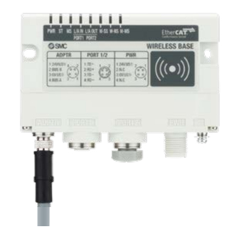
Summary of Product parts EXW1-BECAC Appearance ⑦ ① ① ⑧ ② ③ ④ ⑤ ⑥ Name Application Screw hole for mounting Mounting the compact wireless Base. (2 x M4) Connector for wireless Connect the cable for wireless adaptor. adaptor (ADPTR) Communication connector Connection for the cable for fieldbus inputs. - Page 22 The LED indicators at the top left corner of the compact wireless Base indicate the power supply, communication and diagnostic status. LED indicators of the compact wireless Base LED status Function Description Colour of name ON/Flashing Green The US1 (for control) power supply is ON US1 (for control) power supply status indicator The US1 (for control) power supply is OFF...
- Page 23 LED status Function Colour of Description name ON/Flashing Green All the Remote connections are normal Green Flashing Some Remotes are not connected Flashing No Remotes are connected Wireless No Remotes are connected communication W-NS (Unrecoverable error in wireless communication) connection status Wireless communication connection is being indicator Green...
- Page 24 Connectors •Power supply connector M12, 4-pin, plug Signal A code 24V (US1) N.C. 0V (US1) N.C. •Communication connector For EtherCAT PORT1/PORT2 M12, 4-pin, socket Signal D code TD+ RD+ TD- RD- •Connector for wireless adaptor Signal M8, 4-pin, socket (US1) Internal BUS B 0V(US1)...
-
Page 25: Exw1-A11
EXW1-A11 * Appearance ③ ② ① Name Application ① Connector Connector for Wireless Adaptor cable. ② For fixing to Air Manegement system. ③ LED display Indicates the status of the adaptor. LED status Function Description Colour name ON/Flashing of LED Green Power supply voltage is in ON state Power supply and... -
Page 26: Exw1-Rd
EXW1-RD* Appearance EXW1-RDX*B* ⑥ ① ⑦ ⑤ ⑧ ② ④ ③ Name Application Screw hole for mounting (M4) Mounting the compact wireless Remote. PWR (Power connector) Supplies power to the compact wireless Remote. RF (SMA coaxial connector) * Exclusive to external antenna Connector for the coaxial cable of an external antenna. - Page 27 EXW1-RDY*B* ⑥ ① ⑦ ⑤ ⑧ ② ④ ③ Name Application Screw hole for mounting (M4) Mounting the compact wireless Remote. PWR (Power connector) Supplies power to the compact wireless Remote. RF (SMA coaxial connector) * Exclusive to external antenna Connector for the coaxial cable of an external antenna.
- Page 28 EXW1-RDM*B* ⑥ ① ⑦ ⑤ ② ⑨ ⑧ ④ ③ Name Application Screw hole for mounting (M4) Mounting the compact wireless Remote. PWR (Power connector) Supplies power to the compact wireless Remote. RF (SMA coaxial connector) * Exclusive to external antenna Connector for the coaxial cable of an external antenna.
- Page 29 ○EXW1-RD* The LED indicators at the top right corner of the compact wireless Remote indicate the power supply, communication and diagnostic status. The same LED indications are used for the EXW1-RD*. LED indicators of the compact wireless Remote LED status Function Description ON/Flashi...
- Page 30 Connector (for e-CON) ○EXW1-RDX* PWR (power connector) INPUT (connector for an input device) Pin number Description Pin number Description 24V(US1) 24V(US1) N.C. 0V(US1) 0V(US1) N.C. Circuit diagram ○EXW1-RDY* PWR (power connector) OUTPUT (connector for an output device) Pin number Description Pin number Description 24V(US1)
- Page 31 ○EXW1-RDM* PWR (power connector) INPUT (connector for an input device) Pin number Description Pin number Description 24V(US1) 24V(US1) 24V(US2) 0V(US1) 0V(US1) 0V(US2) OUTPUT (connector for an output device, EXW1- OUTPUT (connector for an output device, EXW1- RDMPE3**) RDMNE3**) Pin number Description Pin number Description...
-
Page 32: Setting And Adjustment
Setting and Adjustment Flow chart for operating the wireless system Flow chart for using the wireless system To use SMC wireless units (Base and Remotes), they need to be set up using an NFC reader/writer and the I/O Configurator. A setup procedure using NFC is shown below. Refer to the operation manual for each manufacturer for how to set the controller and the PLC. -
Page 33: I/O Configurator (Nfc Version)
I/O Configurator (NFC version) EXW1 series supports Ver. 2.10.0 and later versions of the I/O Configurator. In order to use the I/O Configurator (NFC version) it is necessary to install a driver etc. in advance and set the NFC reader/writer on the computer. -
Page 34: Preparation
Preparation Installation of the software Driver: The following drivers should be installed before using this software. •When EXW1-NT1 (NFC reader/writer) is used Obtain the driver software for the NFC reader/writer from the SMC website (https://www.smcworld.com). On the SMC website, select [Documents/Download] and click [Instruction Manuals]. On the product search form of [Instruction Manuals], type "EXW1-NT1"... -
Page 35: Download The I/O Configurator (Nfc Version)
Download the I/O Configurator (NFC version) (1) On the SMC website (https://www.smcworld.com), select [Documents/Download] and click [Instruction Manuals]. (2) Select [Fieldbus System Serial Transmission System]. -34- No.EX※※-OMA1031-B... -
Page 36: Start The I/O Configurator (Nfc Version)
(3) Select the protocol that the product supports. (Example: "EtherCAT compatible" product) (4) Scroll down the page of the Fieldbus System Serial Transmission System and click the Configuration File of I/O Configurator for NFC. Downloading will begin. Start the I/O Configurator (NFC version) Open the downloaded file and double click the IOConfigurator.exe to start the I/O Configurator for NFC. -
Page 37: Screen Layouts Of The I/O Configurator (Nfc Version)
Screen Layouts of the I/O Configurator (NFC Version) (2) (1) Function selecting tab I/O Configurator (NFC version) consists of three function selecting tabs. [Information] •Module information: Displays information on the wireless unit •System configuration: Displays the configuration information of the Base and Remotes (connected units) Only the system configuration of the Base is shown in tree format. - Page 38 (3) Mode switching button "I/O Configurator (NFC version)" has Administrator mode and Monitor mode. To change parameters, operate the configurator in Administrator mode. Administrator mode: available to change the parameters Monitor mode: available to only read the parameters (for confirmation) To enter Administrator mode, type a password while holding the NFC reader/writer near the NFC antenna approach area and click [Confirm].
-
Page 39: Before Starting The Software
Before starting the software <When EXW1-NT1 is used> Follow the steps below to install the driver software. Refer to the operation manual of EXW1-NT1 for details. ●Installation of the driver software When the PC is connected to the Internet, the driver software is automatically installed. Install the driver software again following the steps below. - Page 40 ●Installation does not start automatically. (1) Download the driver software and manual referring to “Downloading of the driver software”. (2) Select language and press the “OK” button. (3) Screen below appears. Press the “Next (N)” button. (4) Screen below appears. Press the “Next (N)” button. -39- No.EX※※-OMA1031-B...
- Page 41 (5) Screen below appears. Press the “Install (I)” button. (6) The screen below appears and installation starts. Please wait. (7) The screen below appears when the installation is complete. Press the「Finish (F)」button. * When the screen requires restarting of the PC, restart the PC. -40- No.EX※※-OMA1031-B...
-
Page 42: Monitoring And Setting Up
Monitoring and setting up To change settings, switch to Administrator mode to operate the configurator. In Administrator mode, a timeout occurs after 300 seconds of inactivity and the application returns to Monitor mode. In Administrator mode, a timeout countdown is displayed to the right of the "Administrator mode" label. ○Operational flow during monitoring A rough operational flow during monitoring is shown below (operations in Monitor mode). -
Page 43: Setting/Adjustment Of The Wireless Unit
Setting/Adjustment of the Wireless Unit Parameter settings of a Remote (optional) Change the parameter settings of the EXW1-RD* Remote. •Remote setting •The setting will be applied when the Remote is turned on (or reset). Remote setting Parameter name Set value Initial value Note 16 points... - Page 44 (1) Module Input size In the case of EXW1-RD*, the number is fixed at 16 (16 bits). * Although the number of occupied inputs of EXW1-RDM* is fixed at 16 (16 bits), only the lower 8 bits are available. (2) Module output size In the case of EXW1-RD*, the number is fixed at 16 (16 bits).
-
Page 45: Parameter Settings Of The Base
Parameter settings of the Base The following two parameter settings are available for the compact wireless Base. •System setting •Remote registration System setting Change parameter settings as required. System setting parameters Classification Parameter Set value Initial value Note I/O mapping Auto Auto Diagnostic allocation... - Page 46 (1) I/O mapping Specifies an I/O mapping method. Setting range: Auto (2) Diagnostic allocation Set the diagnostic information allocated to the I/O map. (Refer to the section " Diagnostic mapping " for details.) Setting range: None: No diagnostic data Simple: System diagnosis Advanced: System diagnosis + Remote connection/diagnosis/registration information (3) Max.
- Page 47 (7) Protocol Sets the wireless communication protocol. * To pair with an EX600-W series unit, V.1.0 must be set. This also applies when building a wireless system consisting of both EXW1 and EX600-W series. •V.1.0: The same wireless communication method as EX600-W is used. The communication speed is 250 kbps.
-
Page 48: Remote Registration
Remote registration Refer to “Pairing and Unpairing Procedures” term for the detail. Item Description Registered List of remotes that are "Registered" or "Registered Wait". Remotes List of remotes that are available to be paired. Free Remotes * Only remotes in pairing mode can be seen. Pairing Select the desired mode (Normal mode / Pairing mode) It is possible to insert dummy remotes. -
Page 49: Frequency Channel Select Function (F.c.s.)
Frequency channel select function (F.C.S.) The frequency channel can be selected using this function. Since only protocol V.2.0 supports it, specify protocol V.2.0 in the system settings when using it. * The number of selectable frequency channels varies depending on the country in use. For more details, check the product number. - Page 50 When FCS Setting is clicked, the following screen is displayed. Item Description Read button Retrieves the current channel selection configuration. The W-LAN indicators make it possible to select frequency channels corresponding W-LAN Channel to W-LAN channel at one time. indicators * In the example above, W-LAN Channel: CH.10 is selected.
-
Page 51: Event
Event This makes it possible to check the event information of the wireless Base or wireless Remotes. The list is sorted from newest to oldest. ・Event Tab 表示 内容 Select the wireless Base or a Remote registered in the wireless (1)... - Page 52 (2) Error Code The error code is displayed. The table below shows error codes and corresponding details and diagnostics maps. Diagnostics map Description Error Code Item Bit No. Detection of a short circuit of US1 or 6 or 7 Detection of the range upper limit Detection of the range lower limit System Detection of unconnected load...
-
Page 53: Wireless
Wireless This screen displays wireless log data. ・Wireless Tab Item 内容 Wireless-Based received data is displayed on the Input tab, and transmission data is displayed on the (1) Input/ Output Tabs Output tab. (2) The wireless channel is displayed. Send Packets (or Received Packets on the (3)... - Page 54 ●Wireless log data file Wireless log data is divided into four csv files as below. -53- No.EX※※-OMA1031-B...
-
Page 55: Pairing And Unpairing Procedures
Pairing and Unpairing Procedures Pairing Procedure Pairing a Base with a Remote Pairing is required for communication between a Base and Remote. A Base is paired with a Remote after they are switched to pairing mode. Pairing and registration between a Base and Remote enables wireless communication. ○Operational flow during pairing (1) Switch the Remote to pairing mode * The pairing mode of EXW1-RD* is set by factory default. - Page 56 (1) Switch the Remote to pairing mode Connect to the Remote using NFC, select the (a) [Properties] tab and then click (b) [Refresh]. Select (d) [Pairing mode] from I [Pairing setting] on the (a) [Properties] tab and then cliI(e) [Reset module].
- Page 57 (2) Switch the Base to pairing mode Connect to the Base using NFC, select the (a) [Properties] tab and then click (b) [Refresh]. Select (d) [Pairing mode]Iom (c) [Remote registration] on the (a) [Properties] tab and thIclick (e) [Reset module]. Base setting screen •A Base unit will change to pairing mode using the protocol set in "System setting".
- Page 58 (3) Pair and register the Base and Remote (a) Clicking [Refresh] causes Remotes in pairing mode to be listed in the Free Remotes area. (b) Select the Remote that is to be rIstered, (c) specify a wireless channel and then (d) click ▲.
- Page 59 The Remote that is to be registered on the specified wireless channel moves to the Registered Remotes area. Make sure that the registration status is Registered Wait, and click [Save reg. info.]. Base setting screen -58- No.EX※※-OMA1031-B...
- Page 60 Click (a) [Reset module] and (b) [Refresh] and check that the registration status changes to Registered. Base setting screen * The example below shows two Remote modules registered on CH1 and CH2. Base setting screen Configure the registration of the dummy Remote as necey. -59- No.EX※※-OMA1031-B...
- Page 61 (4) Disable the Pairing mode of the Base (Normal mode) Connect to the Base using NFC, (a) Select [Normal mode] (b) Click [Reset module] to reseIhe Base. (c) Check connection with registerd Remotes. -60- No.EX※※-OMA1031-B...
- Page 62 •Dummy Remote Set dummy Remotes to secure reserved area in memory and enable Remotes to be added and registered later, without changes to mapping, even after the system has been configured. Register dummy Remotes using the Base. (a) Change the operating mode of the Wireless Base unit (a)-1 Set Remote registration on the Wireless Base unit to "Pairing mode".
- Page 63 ○Switching pairing modes using a button on the Remote Because of the button, a Remote e-CON type does not require the NFC for switching pairing modes. Note that the LED state above indicates that the Base is in Normal mode. When the Base is in pairing mode, W-SS lights up green or flashes -62- No.EX※※-OMA1031-B...
-
Page 64: Unpairing Procedure
Unpairing Procedure Removing Pairing between a Base and Remote Pairing between a Base and Remote will be removed. When you wish to reconfigure the wireless system, such as changing the I/O sizes of a registered Remote, pairing needs to be removed and registered again. ○Operational flow during unpairing (1) Switch the Base to pairing mode (2) Remove pairing between a Base and Remote... - Page 65 (2) Removing the pairing between the Base and Remote Pairing between the Base and Remote will be removed. Click [Refresh]. Select the Remote that you wish to unpair from the registered Remotes and click ▼, which in turn causes the selected Remote to move to the Free Remotes area. Clicking [Save reg. info.] finalizes the unregistration of the Remote.
-
Page 66: Mounting And Installation Of Units
Mounting and Installation of Units EXW1-BECAC, EXW1-RD* Installation Compact wireless Base/Remote Caution To avoid damage to parts, apply the recommended tightening torque. ・ Mount the product using two screws. ・ 2 x M4 screws are required (Recommended torque = 0.8+/-10% N・m). - Page 67 Wireless adaptor Caution ・ To avoid damage to parts, apply the recommended tightening torque. Refer to the operation manual of the Wireless Adaptor for details. ・ (1) Attachment of installation plate Attach the installation plate to the target object by either of the following two methods. Installation with M3 x 4 positions The tightening torque should be 0.4 N•m±10%.
- Page 68 ■External Antenna Caution ・ avoid damage to parts, apply the recommended tightening torque. 2 x M4 screws are required (Recommended torque = 1.3+/-10% N・m). Refer to the operation manual attached to the external antenna set for details. Whip antenna Rotate the whip antenna clockwise to attach it.
- Page 69 Attach the male connector of the coaxial cable to the antenna connector of the wireless unit by rotating it clockwise. (Tightening torque 0.9+/-10%N・m) To install the wireless unit inside a distribution box or other container, pass the coaxial cable through a rubber bushing and into the box in which the wireless unit is installed, and attach its connector to the antenna connector of the wireless unit.
- Page 70 EtherCAT Connect the "PORT1" communication connector to the upstream device (PC, PLC etc.) and connect the "PORT2" communication connector to the downstream device. EtherCAT Master ●Precautions for handling Be sure to fit a seal cap on any unused connectors. Proper use of the seal cap enables the enclosure to achieve IP67 specification -69- No.EX※※-OMA1031-B...
-
Page 71: Troubleshooting
Troubleshooting When problems occur, take appropriate countermeasures while referring to the LED indication, troubleshooting and parameter settings. If a cause applicable to the failure cannot be identified, this indicates that the equipment itself is broken. The fieldbus system damage can be caused by the operating environment. Contact SMC to obtain countermeasures. - Page 72 •Base troubleshooting LED status Problem Possible causes Investigation and countermeasures Colour name ON/Flashing of LED The US1 (for control) power Supply 24 VDC +/-10% for US1 (for supply is OFF control) power source. The US1 (for control) power Supply 24 VDC +/-10% for US1 (for supply is OFF control) power source.
- Page 73 LED status Problem Possible causes Investigation and countermeasures Colour name ON/Flashing of LED (1) Supply 24 VDC +/-10% to the US1 (for control / input) power source of the When Protocol V.1.0 is used Remote. (1) Remote power supply is (2) The distance which wireless Flashing communication between wireless systems...
- Page 74 LED status Problem Possible causes Investigation and countermeasures Colour name ON/Flashing of LED The following Remote After checking the error contents while diagnostic information is referring to the system diagnostic information detected. and LED indication, refer to the following countermeasures. (1) US1 (for control) power As this LED indicates the system status of the supply voltage level is...
- Page 75 LED status Problem Possible causes Investigation and countermeasures Colour name ON/Flashing of LED Check the following and restart. (1) Check if the power is supplied to the EtherCAT device one level above.(When L/A port1 LED is OFF.) LINK has not yet (2) Check that the connectors of L/A port1 been established.
- Page 76 Problem No. Phenomenon Possible causes Investigation and countermeasures Check the following items and check the operation again. •Confirm that the settings of the NFC port and PaSoRi of the PC are correct. •Check that the specifications of the NFC NFC communication is not established reader / writer to be used are appropriate.
- Page 77 •Wireless Adaptor troubleshooting items LED status Description Colour of ON/Flashing All LEDs are OFF. Problem 1 PWR LED is red or flashes orange or Orange Flashing Problem 2 is off. Flashing W-SS LED flashes red or orange or is W-SS Orange Flashing Problem 3...
- Page 78 •Remote I/O unit troubleshooting items LED status Description Colour of ON/Flashing All LEDs are OFF. Problem 1 Flashing PWR LED does not turn on green. Problem 2 Flashing MS LED does not turn on green. Problem 3 Flashing W-SS Red W-SS LED flashes or is OFF. Orange Flashing Problem 4...
- Page 79 •Remote troubleshooting LED status Investigation and Trouble No. Possible causes Colour Name countermeasures ON/Flashing of LED The US1 (for control / input) power Supply 24 VDC +/-10% for US1 supply is OFF (for control / input) power source. Reduction in the US2 (for output) The power supply voltage of the Flashing power voltage (when the setting is...
- Page 80 LED status Investigation and Problem No. Possible causes Colour Name countermeasures ON/Flashing of LED (1) Supply 24 VDC +/-10% for the US1 (for control) power source of the Base. (2) The distance which wireless When Protocol V.1.0 is used communication between (1) Power supply for the Base is wireless systems can be Flashing...
- Page 81 LED status Investigation and Problem No. Possible causes Colour Name countermeasures ON/Flashing of LED (1) Supply 24 VDC +/-10% for the US1 (for control) power source of the Base. (2) The distance which wireless (1) Power supply for the Base is communication between wireless systems can be Flashing...
- Page 82 Problem No. Phenomenon Possible causes Investigation and countermeasures If the polarities (PNP, NPN) of the Remote and Input type does not match. digital input unit do not match, replace one of them to make the combination match. Supply a voltage of 24 VDC +/-10% to the US1 US1 (for control / input) power voltage drop (for control / input) power source of the Remote.
- Page 83 Problem No. Phenomenon Possible causes Investigation and countermeasures Check the following items and check the operation again. •Confirm that the settings of the NFC port and PaSoRi of the PC are correct. •Check that the specifications of the NFC NFC communication is not established reader / writer to be used are appropriate.
-
Page 84: Technical Information
EXW1-series Allocated bytes Diagnostic Unit name Max. Remote units allocation Input Input None 15/31/63 Simple 15/31/63 Compact wireless Base EXW1-BECAC Advanced EXW1-series Allocated bytes Unit name Model Unit product no. Input Output EXW1-RDX*E4** (16 points) EXW1-RDY*E4** Compact wireless Remote (16 points) - Page 85 EX600-W Series Allocated bytes Unit name Model Unit product no. Input Output EX600-WSV* (32 points) EX600-WSV* (24 points) EX600-WSV* Wireless Remote (16 points) EX600-WSV* (8 points) EX600-WSV* (0 points) EX600-DX *B (8 points) EX600-DX *C (8 points) EX600-DX *C1 (8 points) (with broken Digital input unit line detection) (EX600 Series)
-
Page 86: I/O Mapping
I/O Mapping The I/O map is assigned in order of diagnostic information and remote. The remote allocation order to the I/O map is decided by the wireless channel at the remote registration. As they are allocated from the smallest registered channel number, the channel in which no remote is registered will be ignored. (Refer to the figure below.) I/O Map Input data... -
Page 87: Diagnostics Mapping
Diagnostics Mapping The mapping of system diagnostic and Remote connection/diagnostic/registration information is as shown below. Diagnostic allocation None Simple Advanced Input Byte Max. Remote units 15 Remotes 31 Remotes 63 Remotes Reserved (Base Input 0) Reserved (Base Input 1) System Diagnosis 1 System Diagnosis 2 System Diagnosis 3 System Diagnosis 4... -
Page 88: I/O Mapping Order Of Base/Remote
I/O mapping order of Base/Remote The I/O and diagnostic map is shown with the following unit configuration as an example. •The compact wireless Base Diagnostic allocation: detail, Max. Remote units: 15 <Example> Unit 3 Unit 2 Unit 1 Unit 0 DY□B DX□D EX600-WSV*... - Page 89 Input data Output data Module name Unit name Module name Unit name Reserved Reserved Byte0 Base Base Reserved Byte1 Reserved Byte2 System diagnosis 1 Byte3 System diagnosis 2 EX600-WSV* (Unit 0) 32 valve outputs Byte4 System diagnosis 3 Remote Byte5 System diagnosis 4 Wireless channel Remote connection information...
-
Page 90: Diagnostics Map Details
Diagnostics map details When an error occurs in the Base or Remote, a flag will be set in a Bit corresponding to each item of diagnostic information. The errors for the system diagnostics 1 to 4 are for the entire system. Therefore, even if there is only one unit which has an error in the constructed system, a flag will be set in a Bit corresponding to the error content. - Page 91 Diagnosed area and Content of diagnostics processing upon error Remarks How to Item Byte Reset conditions (LED indications, Effective reset processing etc.) Item Details diagnostic upon coverage diagnosis (1) Replace the valve or the output equipment, A short-circuit of the and check the Short-circuit Manual/...
- Page 92 Diagnosed area and Content of diagnostics processing upon error Remarks How to Item Byte Reset conditions (LED indications, Effective reset processing etc.) Item Details diagnostic upon coverage diagnosis Base W-MS: Flashes red Detection of a A voltage drop of the Remote (EXW1) reduction Supply 24 VDC +/-10%...
- Page 93 Diagnosed area and Content of diagnostics processing upon error Remarks How to Item Byte Reset conditions (LED indications, Effective reset processing etc.) Item Details diagnostic upon coverage diagnosis The number of Change the user set occupied value. Or, adjust the Base Number of inputs/outputs of the...
- Page 94 Diagnosed area and Content of diagnostics processing upon error Remarks How to Item Byte Reset conditions (LED indications, Effective reset processing etc.) Item Details diagnostic upon coverage diagnosis Change the user set The number of Number of value. Or, adjust the occupied system system Manual...
- Page 95 Diagnosed area and Content of diagnostics processing upon error Remarks Item Byte Reset conditions (LED indications, Effective I/O processing reset etc.) Item Details diagnostic upon coverage diagnosis Connection condition of the Remote communication (Wireless channel 1) Connection condition of the Remote Remote communication (Wireless channel 2) connection...
- Page 96 Diagnosed area and Content of diagnostics processing upon error Remarks Resister Item Reset conditions (LED indications, Effective I/O processing area reset etc.) Item Details diagnostic upon coverage diagnosis Presence / absence of system information error of Base Presence / absence of system information error of Remote (Wireless channel 1) Presence / absence of system...
- Page 97 Diagnosed area and Content of diagnostics processing upon error Remarks Item Byte Reset conditions (LED indications, Effective I/O processing reset etc.) Item Details diagnostic upon coverage diagnosis Registration of Remote (Wireless channel 1) Registration of Remote Remote (Wireless channel 2) registration information Registration of Remote...
-
Page 98: Esi File
ESI file The ESI file is required to configure the EXW1. The file can be downloaded from the SMC website. URL : https://www.smcworld.com/ ESI file: SMC EXW1-BEC_V##.xm *## : Version number. ■Example of setting using TwinCAT3 XAE This product supports only online configuration. Refer to the manual of TwinCAT3 XAE for details of the operating method. - Page 99 Click OK in the screen below. Select the checkbox and click OK in the screen below. When the comment “Scan for boxes” appears, left click the [YES(Y)] button. Once the scan is successfully completed, [Box 1(EXW1-BEC)] is displayed as shown in the screen below.
-
Page 100: Coe Object
CoE Object You can use the CoE Object Dictionary to check diagnostic data and read and write various parameters. The data format is as follows. ■How to display CoE object After selecting [Box1(EXW1-BEC)], select the [CoE-Online] tab to display the CoE object. ②... - Page 101 ■Modular device profile The wireless network is represented as a modular device in the CoE table. CoE objects for remotes: The slot / subslot system is emulated using the following logic: Index 0xTMMN where: T -> Topic: 6, 7, 8, 9, A for inputs, outputs, parameters, module info and diagnostics respectively M ->...
- Page 102 EXW1-BECAC Parameter settings: Index Name Type Default Value 0xF800:00 Base: Params USINT 0xF800:01 Unit: Brown-out Detection for US1 ENUM0FFF Enable 0xF800:02 Unit: Output State Fieldbus FaultIdle ENUM0FFC Clear 0xF800:03 Unit: Input State for RF Timeout ENUM0FF7 Clear Diagnostics: Object 0xF110. See DETAILED cyclic diagnostics for the contents of this object.
- Page 103 EXW1-RDX* Parameter settings: Index Name Type Default Value 0x8MM1:00 Rem #: Params USINT 0x8MM1:01 Unit: Brown-out Detection for US1 ENUM0FFF Enable Digital Input 0x8MM0:00 Rem #: Params USINT 0x8MM0:01 Unit: Short Circuit Detection (Power) ENUM0FFF Enable 0x8MM0:02 Unit: Inrush Current Filter ENUM0FFF Enable 0x8MM0:03...
- Page 104 Description for the parameters: Parameter Default Name Definition Item Content setting setting range Generated error Unit: Enable ○ Generates an error. when power Brown-out supply voltage Unit Detection for goes under Disable Does not generate an error. approx. 19 V. Generates error ○...
- Page 105 Parameter Default Name Definition Item Content setting setting range Ch #: Counter Limit Counter Limit Times for setting is set value 1~65000 Value (1k- Value x1000 times 65000k) *1: Even though this parameter is represented, not supported. *2: The count is stored once every hour or when the power supply drops below approx. 19 V. When the power supply is restored, counting starts from the last value stored.
- Page 106 Diagnostics: Index Name Type Default Value Digital Input 0xAMM0:00 Rem.#: Diags USINT 0xAMM0:01 Ch #:ON/OFF Counter Value UDINT -0xAMM0:10 0xAMM0:11 Ch #:ON/OFF Counter Clear USINT -0xAMM0:20 0xAMM0:21 Ch 7-0:Exceeded ON/OFF Counter Limit USINT 0xAMM0:22 Ch 15-8:Exceeded ON/OFF Counter Limit USINT 0xAMM0:23 Ch 7-0:Open Circuit Detection USINT...
- Page 107 ・Diagnostics details Name Definition Type Value Ch #: ON/OFF 0 — 4294967295 ON/OFF count UDINT Counter (0 to 0xFFFFFFFF) upper limit value Value Ch #: Clears the Input ON/OFF USINT ON/OFF counter Set to 0 Counter to 0. Clear ON/OFF count of 0: No error Ch 7-0: the valve has...
- Page 108 EXW1-RDY* Parameter settings: Index Name Type Default Value 0x8MM1:00 Rem.#: Params USINT 0x8MM1:01 Unit: Brown-out Detection for US1 ENUM0FFF Enable 0x8MM1:02 Unit: Brown-out Detection for US2 ENUM0FFF Disable 0x8MM1:03 Unit: Output State Fieldbus FaultIdle ENUM0FFC Clear 0x8MM1:04 Unit: Output State for RF Timeout ENUM0FFC Hold Digital Output...
- Page 109 Description for the parameters: Parameter Default Name Definition Item Content setting setting range Generated error Unit: Enable ○ Generates an error. when power Brown-out supply voltage Unit Detection for (US1) goes under Disable Does not generate an error. approx. 19 V. Generated error Unit: ○...
- Page 110 Parameter Default Name Definition Item Content setting setting range 0: Hold the output Ch 7-0: 0:Hold 1: Depend on output state Hold State 1:Depend on Bit0:Channel 0 Channel for Fieldbus Output state ○ : Sets hold status Fault *2*3 Digital Value Bit7:Channel 7 when Fieldbus Communication...
- Page 111 Parameter Default Name Definition Item Content setting setting range Sets hold status 0: Hold the output Ch 15-8: Hold when Wireless 1: Depend on output state Hold State Depend on Bit0:Channel 8 Communication Channel for RF ○ Fault Digital : timeout is Timeout Value...
- Page 112 Diagnostics: Index Name Type Default Value Digital Output 0xAMM0:00 Rem.#: Diags USINT 0xAMM0:01 Ch #:ON/OFF Counter Value UDINT -0xAMM0:10 0xAMM0:11 Ch #:ON/OFF Counter Clear USINT -0xAMM0:20 0xAMM0:21 Ch 7-0:Exceeded ON/OFF Counter Limit USINT 0xAMM0:22 Ch 15-8:Exceeded ON/OFF Counter Limit USINT 0xAMM0:23 Ch 7-0:Open Circuit Detection USINT...
- Page 113 ・Diagnostics details Name Definition Type Value Ch #: ON/OFF 0 — 4294967295 ON/OFF count UDINT Counter (0 to 0xFFFFFFFF) upper limit value Value Ch #: Clears the Input ON/OFF USINT ON/OFF counter Set to 0 Counter to 0. Clear ON/OFF count of 0: No error Ch 7-0: the valve has...
- Page 114 EXW1-RDM* Parameter settings: Index Name Type Default Value 0x8MM2:00 Rem.#: Params USINT 0x8MM2:01 ENUM0FFF Enable Unit: Power Supply Voltage Monitor US1 0x8MM2:02 Unit: Power Supply Voltage Monitor US2 ENUM0FFF Disable 0x8MM2:03 Unit: Output State Fieldbus FaultIdle ENUM0FFC Clear 0x8MM2:04 Unit: Output State for RF Timeout ENUM0FFC Hold Digital Input...
- Page 115 Diagnostics: Index Name Type Default Value Digital Input 0xAMM0:00 Diags USINT 0xAMM0:01 Ch #:ON/OFF Counter Value UDINT -0xAMM0:08 0xAMM0:09 Ch #:ON/OFF Counter Clear USINT -0xAMM0:10 0xAMM0:11 Ch 7-0:Exceeded ON/OFF Counter Limit USINT 0xAMM0:12 Ch 7-0:Open Circuit Detection USINT 0xAMM0:13 Ch 7-0:Short Circuit Detection(Input) USINT Digital Output 0xAMM1:00...
-
Page 116: Specifications
Specifications Dimensions ○EXW1-BECAC -115- No.EX※※-OMA1031-B... - Page 117 ○EXW1-A11* ・Wireless Adaptor ・Installation Plate -116- No.EX※※-OMA1031-B...
- Page 118 ○EXW1-RD* -117- No.EX※※-OMA1031-B...
-
Page 119: Specifications Table
Specifications Table ○EXW1-BECAC EtherCAT communication specifications Item Specification Protocol EtherCAT (Conformance Test Record V.2.3.0) Transmission speed 100 Mbps Occupied area Max. 11784 / 11784 (Inputs/ outputs) (1473 byte / 1473 byte) Configuration file ESI file *1 Configuration Online *2 *1: The setting file can be downloaded from the SMC Web site *2: The control component (PLC etc..) should be supported an online configuration. - Page 120 ○EXW1-A11* Electrical specifications Item Specification US1 (for control) power supply 24 VDC+/-10 % voltage range Current consumption 50 mA or less General specifications Item Specification Enclosure IP67 Ambient operating temperature -10 to +50 Ambient storage temperature -20 to +60 Ambient humidity 35 to 85% RH (no condensation) EN61131-2 compliant 5≦f<8.4 Hz 3.5 mm...
- Page 121 ○EXW1-RDX* The wireless communication specifications are the same as EXW1-A11*. General specifications Item Specification Enclosure IP20 Ambient operating temperature -10 to +50 Ambient storage temperature -20 to +60 Ambient humidity 35 to 85% RH (no condensation) 500 VAC 1.0 min. External terminals (including the FE terminal) and Withstand voltage enclosure screws 10 MΩ...
- Page 122 ○EXW1-RDY* The wireless communication specifications are the same as EXW1-A11*. General specifications Item Specification Enclosure IP20 Ambient operating temperature -10 to +50 Ambient storage temperature -20 to +60 Ambient humidity 35 to 85% RH (no condensation) 500 VAC 1.0 min. External terminals (including the FE Withstand voltage terminal) and enclosure screws 10 MΩ...
- Page 123 ○EXW1-RDM* The wireless communication specifications are the same as EXW1-A11*. General specifications Item Specification Enclosure IP20 Ambient operating temperature -10 to +50 Ambient storage temperature -20 to +60 Ambient humidity 35 to 85% RH (no condensation) 500 VAC 1.0 min. External terminals (including the FE Withstand voltage terminal) and enclosure screws 10 MΩ...
-
Page 124: Accessories
Accessories Accessory List For the selection of accessories, refer to the catalog. (1) Power supply cables EX500-AP010-S: Cable with M12 connector, A code, Socket, Straight 1 m EX500-AP050-S: Cable with M12 connector, A code, Socket, Straight 5 m EX500-AP010-A: Cable with M12 connector, A code, Socket, Angle 1 m EX500-AP050-A: Cable with M12 connector, A code, Socket, Angle 5 m PCA-1401804: Cable with M12 connector, A code, Socket, Straight 1.5 m, SPEEDCON compatible... - Page 125 (6) External antenna set EXW1-EA1 This set includes a whip antenna, a coaxial cable (1.5 m), a bracket and two screws (M2.6 x 8). (7)e-CON ZS-28-□ Conductor e-CON cross Wire O.D. connector Part AWG No. Color of cover sectional area (mm) (mm SQ) ZS-28-C-1...
- Page 126 (8) NFC reader/writer EXW1-NT1 This set includes an NFC reader/writer and a USB extension cable (2.95 m). (9) NFC reader/writer holder EXW1-AB1 (for EX600-W) EXW1-AB2 (for EXW1) -125- No.EX※※-OMA1031-B...
- Page 127 Revision history 4-14-1, Sotokanda, Chiyoda-ku, Tokyo 101-0021 JAPAN Tel: + 81 3 5207 8249 Fax: +81 3 5298 5362 https://www.smcworld.com Note: Specifications are subject to change without prior notice and any obligation on the part of the manufacturer. EtherCAT® is a registered trademark and patented technology, licensed by Beckhoff Automation GmbH, Germany. ©...
Need help?
Do you have a question about the EXW1-BECAC and is the answer not in the manual?
Questions and answers