SMC Networks EX600 Series Operation Manual
Fieldbus system profibus dp compatible si unit
Hide thumbs
Also See for EX600 Series:
- Operation manual (138 pages) ,
- Opration manual (82 pages) ,
- Operation manuals (1 page)

Related Manuals for SMC Networks EX600 Series


Summary of Contents for SMC Networks EX600 Series
- Page 1 No.EX※※-OMN0028-D PRODUCT NAME Fieldbus system PROFIBUS DP compatible SI unit MODEL / Series / Product Number EX600-SPR#A EX600-ED#...
- Page 2 Table of Contents Safety Instructions System Outline Definition and terminology Assembly Mounting and Installation Installation Wiring SI Unit Model Indication and How to Order Summary of Product parts Mounting and Installation Wiring Setting and Adjustment LED Display Specifications Dimensions End plate Model Indication and How to Order Summary of Product parts Mounting and Installation...
- Page 3 Safety Instructions These safety instructions are intended to prevent hazardous situations and/or equipment damage. These instructions indicate the level of potential hazard with the labels of “Caution,” “Warning” or “Danger.” They are all important notes for safety and must be followed in addition to International Standards (ISO/IEC) , and other safety regulations.
- Page 4 Safety Instructions Caution We develop, design, and manufacture our products to be used for automatic control equipment, and provide them for peaceful use in manufacturing industries. Use in non-manufacturing industries is not covered. Products we manufacture and sell cannot be used for the purpose of transactions or certification specified in the Measurement Act.
- Page 5 Operator This operation manual is intended for those who have knowledge of machinery using pneumatic equipment, and have sufficient knowledge of assembly, operation and maintenance of such equipment. Only those persons are allowed to perform assembly, operation and maintenance. Read and understand this operation manual carefully before assembling, operating or providing maintenance to the product.
- Page 6 Caution ■When handling the unit or assembling/replacing units: •Do not touch the sharp metal parts of the connector or plug for connecting units. •Take care not to hit your hand when disassembling the unit. The connecting portions of the unit are firmly joined with seals. •When joining units, take care not to get fingers caught between units.
- Page 7 ●Product handling Installation •Do not drop, hit or apply excessive shock to the SI unit. Otherwise damage to the product can result, causing malfunction. •Tighten to the specified tightening torque. If the tightening torque is exceeded the mounting screws may be broken. IP67 protection cannot be guaranteed if the screws are not tightened to the specified torque.
- Page 8 •When a surge-generating load such as a relay, valve or lamp is driven directly, use a product with a built-in surge absorbing element. Direct drive of a load generating surge voltage can damage the unit. •The product is CE marked, but not immune to lightning strikes. Take measures against lightning strikes in the system.
- Page 9 System Outline •System configuration The EX600 range of units can be connected to various types of Fieldbus to realize the reduction of input or output device wiring and the distributed control system. The unit communicates with the Fieldbus through the SI unit.
- Page 10 ■Definition and terminology Terminology Definition Address A number assigned to identify the unit connected onto the PROFIBUS DP network. (Station Address) It must not be duplicated. The signal from the analogue input device is converted to digital, and displayed in AD value decimal and hexadecimal.
- Page 11 Terminology Definition Abbreviation of programmable logic controller. A digital computer used for automation of electromechanical processes. PNP input Takes the sensor output that uses the PNP transistor to the signal output part. The output type that uses a PNP transistor to operate output device. It is also known PNP output as a negative common type since a negative potential is applied to the power supply line.
- Page 12 Assembly •Composing the unit as a manifold : If the unit was purchased as a manifold, the work described in this section is not necessary. (1) Connect the unit to the end plate. The Digital unit, Analogue unit can be connected in any order. Tighten the bracket of the joint using tightening torque 1.5 to 1.6 N•m.
- Page 13 (4) Mounting the valve plate. Mount the valve plate (EX600-ZMV#) to the valve manifold using the valve set screws. (M3 x 8) Apply 0.6 to 0.7 N•m tightening torque to the screws. Screw mounting place : 2 places S0700 : 2 places VQC1000 : 2 places VQC2000...
- Page 14 Mounting and Installation ■Installation •Direct mounting (1) When joining six or more units, fix the middle part of the complete EX600 unit with an intermediate reinforcing brace (EX600-ZMB1) before mounting using 2-M4 x 5 screws. Tightening torque: 0.7 to 0.8 N•m. (2) Fix and tighten the end plates at one end of the unit.
- Page 15 •DIN rail mounting (Available for series other than SY series. Refer to the catalog for SY series.) (1) When joining six or more units, fix the middle part of the complete EX600 unit with an intermediate reinforcing brace (EX600-ZMB2) before mounting, using 2-M4 x 6 screws. Tightening torque: 0.7 to 0.8 N•m.
- Page 16 ■Wiring •Connect the M12 or M8 connector cable. M12 connector is applicable for SPEEDCON connector. SPEEDCON connector wiring method is explained below. (1) Align the mark B on the metal bracket of the cable side connector (plug/socket) with the mark A. (2) Align the mark C on the unit and insert the connector into the unit vertically.
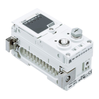
- Page 17 SI unit Model Indication and How to Order EX600-S SI Unit Polarity of output Symbol Content Protocol PNP (Negative common) Symbol Content NPN (Positive common) PROFIBUS DP Summary of Product parts Description Function Status display LED Displays the status of the unit. Display cover Open for the setting of switch.
- Page 18 Mounting and Installation ■Wiring ○Connector pin assignment and circuit diagram •Connector pin assignment Configuration Pin No. Signal name BUS IN BUS OUT RXD/TXD-N RXD/TXD-P Shield •Circuit diagram The product has T branching internally in the unit as shown in the circuit diagram below. It can be extended by connecting the PROFIBUS DP slave with BUS OUT.
- Page 19 Setting and Adjustment •Switch setting (1) Loosen the display cover screw (indicated by arrow). (2) Open the display cover using a flat head screwdriver, etc. (3) Set the switch using a small watchmaker's screwdriver with a thin blade, referring to the setting of switch on the following pages.
- Page 20 •Address setting switch: Set the PROFIBUS DP node address. Address setting switch (x10): Sets the 10 digit of the PROFIBUS DP node address. Address setting switch (x1): Sets the 1 digit of the PROFIBUS DP node address. Settings1 switch (8): Sets the 3 digit of the PROFIBUS DP node address.
-
Page 21: Byte
•V_SEL switch: A function to select the number of occupied valve outputs. The number of outputs (size) occupied by the SI unit is selected. Settings1 Content SI unit output data size Number of occupied valve 32 outputs 4 byte (Default setting) Number of occupied valve 24 outputs 3 byte Number of occupied valve 16 outputs... - Page 22 •Terminator switch: Sets the terminal resistor of the PROFIBUS DP communication line. Setting of the terminal resistor Terminal resistor OFF Terminal resistor ON Terminal resistor OFF (Default setting) ●Precautions for handling •When the product is connected to at the end of the PROFIBUS communication line, be sure to set it to “Terminal resistor ON”.
- Page 23 LED Display The status display LED displays the power supply and communication status. Various kinds of status can be checked as follows: Display Content ST(M) Displays the diagnosis status of the unit. Displays the status of the power supply voltage for control and input. PWR(V) Displays the status of the power supply voltage for outputs.
- Page 24 •PWR(V)-LED LED Display Contents Power supply voltage for output is OFF or the voltage level is abnormal. (When diagnostics is not activated) The power supply voltage level for output is normal. Green LED is ON Power supply voltage for output is OFF or the voltage level is abnormal. (When diagnostics is activated) Red LED is ON : Refer to”Ttroubleshooting”...
- Page 25 Specifications Model EX600-SPR1A EX600-SPR2A Fieldbus PROFIBUS DP (DP-V0) Device type PROFIBUS DP 9.6/19.2/45.45/93.75/187.5/500 kbps Communication speed 1.5/3/6/12 Mbps Configuration file GSD (SMCB1411.gsd) Occupied area (512 inputs/512 outputs) max. (Number of inputs/outputs) Power supply (control and input) 24 VDC Class 2, 2 A Terminal resistor Internally implemented (For type A cable) Internal current consumption...
- Page 26 ■Dimensions -26- No.EX※※-OMN0028-D...
- Page 27 End plate Model Indication and How to Order EX600-ED - End plate at D side Mounting method Symbol Description Connector No DIN rail bracket Symbol Connector Key type Function With DIN rail bracket (VQC/SV/S0700 valve) M12 (5-pin) B-coded With DIN rail bracket (SY/JSY valve) 7/8 inch (5-pin) IN/OUT...
- Page 28 Summary of Product parts •EX600-ED2-# •EX600-ED3-# •EX600-EU1-# Description Function Power connector Connector for power supply to SI unit and I/O unit. Fixing hole for direct mounting Holes for direct mounting. DIN rail fixing hole Holes for fix DIN rail mounting. Functional Earth terminal - must be connected directly to system earth ...
- Page 29 •EX600-ED4/ED5-# Description Function Power connector (PWR IN) Supplies power for each unit and input/output devices. Power connector (PWR OUT) Provides power to downstream equipment. Fixing hole for direct mounting Holes used for direct mounting. DIN rail fixing hole Holes used for fix DIN rail. Functional Earth terminal - must be connected directly to system earth ...
- Page 30 Mounting and Installation ■Wiring ○Connector pin assignment (1) EX600-ED2-# PWR IN: M12 5-pin Plug B-coded Configuration Pin No. Signal name 24 V (Output) 0 V (Output) 24 V (Control and input) (Control and input) F.E. (2) EX600-ED3-# PWR IN: 7/8 inch 5-pin Plug Configuration Pin No.
- Page 31 ○Regarding the 2 types of power supply The power supply consists of two power supply systems as follows: •Power supply for control and input: Supplying power for control of each unit’s power supply for control and also for device connected to input port of Digital and Analogue unit. •Power supply for output: Supplying power for equipment connected to output port of Digital and Analogue unit, and also power supply for solenoid valve manifold.
- Page 32 Specifications Model EX600-ED2-# EX600-ED3-# EX600-ED4-# EX600-ED5-# M12 (5-pin) 7/8 inch (5-pin) M12 (4-pin) M12 (4-pin) PWR IN Plug Plug Plug Plug Power connector M12 (5-pin) M12 (5-pin) PWR OUT Socket Socket Power supply 24 VDC ±10%, 24 VDC ±10%, DC24 V ±10%, (Control and input) 24 VDC +10/-5%, 24 VDC +10/-5%,...
- Page 33 ■Dimensions •EX600-ED2 -33- No.EX※※-OMN0028-D...
- Page 34 •EX600-ED2-2 -34- No.EX※※-OMN0028-D...
- Page 35 •EX600-ED2-3 -35- No.EX※※-OMN0028-D...
- Page 36 •EX600-ED3 •EX600-ED3-2 -36- No.EX※※-OMN0028-D...
- Page 37 •EX600-ED3-3 -37- No.EX※※-OMN0028-D...
- Page 38 •EX600-ED4/ED5 -38- No.EX※※-OMN0028-D...
- Page 39 •EX600-ED4/ED5-2 -39- No.EX※※-OMN0028-D...
- Page 40 •EX600-ED4/ED5-3 -40- No.EX※※-OMN0028-D...
- Page 41 •EX600-EU1 •EX600-EU1-2 -41- No.EX※※-OMN0028-D...
- Page 42 •EX600-EU1-3 -42- No.EX※※-OMN0028-D...
- Page 43 Maintenance Turn off the power supply, stop the supplied air, exhaust the residual pressure and verify the release of air before performing maintenance. Cleaning method Use a soft cloth to remove stains. For heavy stains, use a cloth soaked with diluted neutral detergent and fully squeezed, then wipe up the stains again with a dry cloth.
- Page 44 Troubleshooting •Troubleshooting When any failure happens with this fieldbus system, the following chart is used to identify the cause of the failure. Error status is reflected from the parameter setting of the fieldbus system. When a failure occurs, take the appropriate countermeasures referring to the LED display, the troubleshooting and the parameter setting.
- Page 45 SI unit Refer to failure 8. Red ST(M) LED is flashing. Red ST(M) LED is On. Refer to failure 9. Or red/green ST(M) LED is flashing alternately. Red PWR or PWR(V) Refer to failure 10. LED is On. At least one SF and/or Refer to failure 11.
- Page 46 •Trouble counter measure method Part No. Problem Presumed cause Troubleshooting EX600- The system The types of units that can be connected vary depending Inappropriate unit does not work on the SI unit part number. Check if the unit is applicable selection.
- Page 47 Part No. Problem Presumed cause Troubleshooting EX600- Red LED is ON. Diagnosis error Check the parts with error by using the LED display or (When Output device is or H.T. Re-wire the short-circuited part or check if diagnosis is short-circuited.
- Page 48 Part No. Problem Presumed cause Troubleshooting EX600- Red LED is ON. Diagnosis error Check the parts with error by using the LED display or (When Analogue input device or H.T. Re-wire the short-circuited part, and check diagnosis is power supply is if the cable and analogue input device are normal.
- Page 49 Part No. Problem Presumed cause Troubleshooting EX600- Red LED is Diagnosis error Check the parts with error by using the LED display or Analogue input or output or H.T. Re-wire the short-circuited part, and check (When device power supply is if the cable and analogue input or output device are diagnosis is short-circuited.
- Page 50 Problem Presumed cause Troubleshooting SF: Red LED is ON Diagnosis error BF: OFF Check the LED display of each unit, and take (Among PLC and each (When diagnosis is countermeasures referring to failure No.2 to7. unit) activated) Check the proper wiring length for the communication speed.
- Page 51 Problem Presumed cause Troubleshooting If the polarity (PNP, NPN) of the input unit and the input Polarity of input does not device are different, replace one of them to make the match. combination match. Check if the green Power LED of the SI unit is on. If the Power supply for control LED is OFF, or the red LED is on, supply 24 VDC ±10% and input is abnormal.
- Page 52 Problem Presumed cause Troubleshooting Check if the green Power LED of the SI unit is ON. If the Power supply for control LED is OFF, or the red LED is ON, supply 24 VDC ±10% and input is abnormal. to the power supply for control and input. Analogue input signal Check the analogue input device specification, and set range setting failure.
- Page 53 Parameter Setting The product has parameters that can be set for the system, each unit or each channel. The parameters can be changed using the PLC and H.T. There is no order of precedence of the PLC and H.T. The latest parameter settings are used. ●Precautions for handling •Changing parameters with the H.T.
- Page 54 •SI unit parameters Parameter setting Parameter Default Definition Item Content (H.T. Symbol) setting H.T. Generated error per Power supply ○ Enable Generates an error. unit when control and for control and input power supply ○ ○ input voltage voltage goes over monitor approx.
- Page 55 •Digital input unit parameters Parameter setting Parameter Default Definition Item Content (H.T. Symbol) setting H.T. The power Generates error per ○ Enable Generates an error. supply short unit when the short circuit detection ○ ○ circuit of the power for control and supply for the input input Disable...
- Page 56 •Digital output unit parameters Parameter setting Parameter Default Definition Item Content (H.T. Symbol) setting H.T. Output load Generates error per ○ Enable Generates an error. short circuit unit when the short ○ ○ detection circuit of the output Disable Does not generate an error. 1 (SC_MonOp) device is detected.
- Page 57 •Digital I/O unit parameters Parameter setting Parameter Default Definition Item Content (H.T. Symbol) setting H.T. The power supply Generates error per ○ Enable Generates an error. short circuit unit when the short ○ ○ detection for circuit of the control control and input or input power supply Disable...
- Page 58 •Analogue input unit parameters Parameter setting Parameter Default Definition Item Content (H.T. Symbol) setting H.T. The power supply short Generates error per ○ Enable Generates an error. circuit unit when the short ○ ○ detection for circuit of the power the input supply for the input Disable...
- Page 59 Upper and lower setting limit of user setting. Analogue input measurement range. (Range) (Lwr_Lmt) (Upr_Lmt) -10..10 V -10.50 to +10.45 V -10.45 to +10.50 V -5..5 V - 5.25 to + 5.22 V - 5.22 to +5.25 V -20..20 mA -21.00 to +20.90 mA -20.90 to +21.00 mA 0..10 V...
- Page 60 •Analogue output unit parameters (1) Parameter setting Parameter Default Definition Item Content (H.T. Symbol) setting H.T. The power supply short ○ Enable Generates an error. Generates error per circuit unit when the short ○ ○ detection for circuit of the output the output device is detected.
- Page 61 •Analogue output unit parameters (2) Parameter setting Parameter Default Definition Item Content (H.T. Symbol) setting H.T. Output setting 2 Sets output per Enable Val is output. channel during ○ communication × communication 3 idling ○ Disable The output is held. idling.
- Page 62 •Analogue I/O unit parameters (1) Parameter setting Parameter Default Definition Item Content (H.T. Symbol) setting H.T. The power Generates error per supply short ○ Enable Generates an error. unit when the short circuit circuit of the input ○ ○ detection for device power supply the input or or output device is...
- Page 63 •Analogue I/O unit parameters (2) Parameter setting Parameter Default Definition Item Content (H.T. Symbol) setting H.T. Generates error per User’s set 2 Enable Generates an error. channel when the value lower input or output value limit error falls below the set ○...
- Page 64 Hardware Configuration ■GSD file and icon GSD file is required to configure the EX600 with a DP Master. The GSD File contains ID number, version, and unit information. Furthermore, icons are necessary for the display icon of the EX600 on the DP Master Software.
- Page 65 ■SIEMENS PLC S7 connection method Below is an explanation of the EX600 Series connection method with a SIEMENS’ PLC STEP7™. Refer to the manual of STEP7™ for a detailed manner of operation. •GSD File Installation There are 2 methods for installing the EX600-SPR# GSD file.
- Page 66 •Adding Stations (1) Drag and drop [EX600-SPR1/2] from [Hardware Catalogue] window to the line of [PROFIBUS: DP master system]. (2) [Property-PROFIBUS Interface EX600-SPR1/2] window will be displayed. (3) Enter the unit address on the dialogue box. Please make sure that the address entered is the same as the address set, using the SI unit switches.
- Page 67 •Adding Units (1) Select [EX600-SPR1/2] from [station] window. (2) An empty slot for [EX600-SPR1/2] will be displayed on [Configuration table] window. (3) Drag and drop the connected unit from [Hardware Catalogue] window to slot 1. Please make sure to add the unit as the real system’s order of connecting.
- Page 68 ■Parameter setting at PLC •System Parameter Setting (1) Double click the [EX600-SPR1/2] icon on the line of [PROFIBUS: DP master system]. [Properties – DP slave] window will be displayed. (2) Select the [Parameter Assignment] tab, the available Parameter setting list will be displayed. (3) Change the parameter value by clicking on the [Value] column of the selected parameter.
- Page 69 •Unit Parameter Setting (1) Double click a unit that you want to set on the [Configuration table] window. [Properties – DP slave] window will be displayed. (2) Select the [Parameter Assignment] tab, the available Parameter setting list will be displayed. (3) Change the parameter value by clicking on the [Value] column of the selected parameter.
- Page 70 I/O Map Each unit of the product has its own identification (ID) number. Occupied byte ID number Unit Unit part number Input Output Siemens IEC61158 EX600-SPR#A 32DO (32 outputs) EX600-SPR#A 24DO (24 outputs) SI unit EX600-SPR#A 16DO (16 outputs) EX600-SPR#A (8 outputs) EX600-DX#B (8 inputs)
- Page 71 Diagnostic The diagnosis mode is set by the system parameter “Diag. mode”. (Refer to “System parameters” (page 53) for details.) Diagnostic Mode Content No diag. Outputs the standard diagnosis information. Device diag. Outputs the standard and system diagnosis information. Device + Module diag. Outputs the standard, system and unit diagnosis information.
-
Page 72: Table Of Contents
•Diagnosis map Byte No. Content Diagnostic type Byte 0 Station status 1 Byte 1 Station status 2 Byte 2 Station status 3 Standard diagnostic data Byte 3 Master PROFIBUS DP address Byte 4 Manufacturer ID (MSB: 14h) Byte 5 Manufacturer ID (LSB: 11h) Byte 6 Header Byte 7... -
Page 73: Station Status
•Standard diagnostic data •Station status 1 Byte 0 Bit No. Content 1: The slave cannot be accessed by the master. 1: The slave is not ready to exchange data. 1: The configuration data sent from the master to the slave is not consistent with the setting of the slave. 1: The external diagnosis is available. -
Page 74: Header
•System diagnostic data •Header Byte 6 Bit No. Content 0 to 7 0Eh: The number of bytes of the system diagnosis information (fixed to 13 bytes). •System diag.1 Byte 7 Bit No. Content 1: The analogue input or output value has fallen below the user’s set value. 1: The analogue input or output value has exceeded the user’s set value. -
Page 75: Byte
•System diag.3 Byte 9 Bit No. Content 0 to 7 Reserved •System diag.4 Byte 10 Bit No. Content 1: There is an error in the digital input unit. 1: There is an error in the digital output unit. 1: There is an error in the analogue input unit. 1: There is an error in the analogue output unit. - Page 76 •Unit standard diagnostic data •Header Byte 19 Bit No. Content 0 to 5 09h: The number of bytes of the unit diagnosis information (fixed to 9 bytes). (This bit is fixed to 1) (This bit is fixed to 0) •Unit 0 to 7 Byte 20 Bit No.
- Page 77 •Channel diagnostic data The channel diagnosis information is 3 bytes, and handles a maximum of 12 errors. However, each unit can output only 1 error, and will output the error with a smaller channel number when it multiple errors have been generated. Unit number Byte 28 Channel number...
- Page 78 •Diagnostic type Bit No. Content 0 to 4 Error code Channel type: 001 = Bit (Unit other than analogue unit), 101 = Word (Analogue unit) •Error code Error code 1 Content Level Binary Decimal 00000 Reserved 00001 The short circuit has been detected. 00010 Reserved 00101...
- Page 79 Accessories For the selection of accessories, refer to the catalog. (1) Valve plate EX600-ZMV1 Enclosed parts: Round head screw (M4 x 6), 2 pcs. Round head screw (M3 x 8), 4 pcs. EX600-ZMV2 (Specified for SY series) Enclosed parts: Round head screw (M4 x 6), 2 pcs. Roun1d head screw (M3 x 8), 4 pcs.
- Page 80 (4) Seal cap (10 pcs.) EX9-AWES…for M8 EX9-AWTS…for M12 (5) Marker (1 sheet, 88 pcs.) EX600-ZT1 (6) Y Junction connector PCA-1557785 2 x M12 (3-pin) – M12 (5-pin) (7) Assembled type connector PCA-1578078 for power supply, 7/8 inch, Plug, Cable O.D. 12 to 14 mm PCA-1578081 for power supply, 7/8 inch, Socket, Cable O.D.
- Page 81 Revision history A: Revision (Pollution degree) B: Contents revised in several places. C: Contents revised in several places. [February 2022] D: Contents revised in several places. [January 2024] Tel: + 81 3 5207 8249 Fax: +81 3 5298 5362 https://www.smcworld.com Note: Specifications are subject to change without prior notice and any obligation on the part of the manufacturer.
Need help?
Do you have a question about the EX600 Series and is the answer not in the manual?
Questions and answers