SMC Networks EX600-AXA Operation Manual
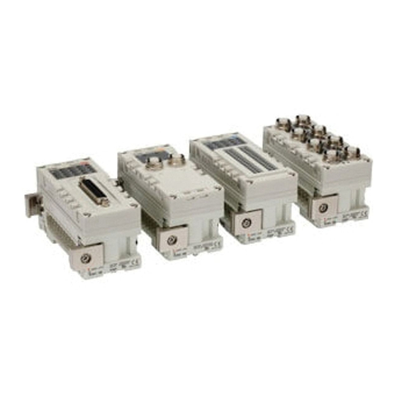
Fieldbus system analog unit
Hide thumbs
Also See for EX600-AXA:
- Operation manual (70 pages) ,
- Installation & maintenance manual (2 pages)

Subscribe to Our Youtube Channel
Related Manuals for SMC Networks EX600-AXA


Summary of Contents for SMC Networks EX600-AXA
- Page 1 No.EX※※-OMN0038-D PRODUCT NAME Fieldbus system Analog unit MODEL / Series / Product Number EX600-AXA EX600-AYA EX600-AMB...
-
Page 2: Table Of Contents
Table of Contents Safety Instructions System Outline Assembly Mounting and Installation Installation Wiring Analog input unit Model Indication and How to Order Names and Functions of Product Mounting and Installation Wiring LED Display Specification Specifications Dimensions Analog output unit Model Indication and How to Order Names and Functions of Product Mounting and Installation Wiring... - Page 3 Common items Maintenance Troubleshooting Parameter Setting I/O Map Diagnostic Accessories Precautions before mounting No.EX※※-OMN0038-D...
-
Page 4: Safety Instructions
Safety Instructions These safety instructions are intended to prevent hazardous situations and/or equipment damage. These instructions indicate the level of potential hazard with the labels of “Caution,” “Warning” or “Danger.” They are all important notes for safety and must be followed in addition to International Standards (ISO/IEC) , and other safety regulations. -
Page 5: Limited Warranty And Disclaimer/Compliance Requirements
Safety Instructions Caution We develop, design, and manufacture our products to be used for automatic control equipment, and provide them for peaceful use in manufacturing industries. Use in non-manufacturing industries is not covered. Products we manufacture and sell cannot be used for the purpose of transactions or certification specified in the Measurement Act. - Page 6 Operator ♦This operation manual is intended for those who have knowledge of machinery using pneumatic equipment, and have sufficient knowledge of assembly, operation and maintenance of such equipment. Only those persons are allowed to perform assembly, operation and maintenance. ♦Read and understand this operation manual carefully before assembling, operating or providing maintenance to the product.
- Page 7 Caution When handling the unit or assembling/replacing units: ■ •Do not touch the sharp metal parts of the connector or plug for connecting units. •Take care not to hit your hand when disassembling the unit. The connecting portions of the unit are firmly joined with seals. •When joining units, take care not to get fingers caught between units.
- Page 8 ●Product handling ∗Installation •Do not drop, hit or apply excessive shock to the SI unit. Otherwise damage to the product can result, causing malfunction. •Tighten to the specified tightening torque. If the tightening torque is exceeded the mounting screws may be broken. IP67 protection cannot be guaranteed if the screws are not tightened to the specified torque.
- Page 9 •When a surge-generating load such as a relay, valve or lamp is driven directly, use a product with a built-in surge absorbing element. Direct drive of a load generating surge voltage can damage the unit. •The product is CE/UKCA marked, but not immune to lightning strikes. Take measures against lightning strikes in the system.
-
Page 10: System Outline
System Outline •System configuration The EX600 range of units can be connected to various types of Fieldbus to realize the reduction of input or output device wiring and the distributed control system. The unit communicates with the Fieldbus through the SI unit. One SI unit can be connected with manifold valves with up to 32 outputs and the input • output • I/O units with maximum 10 units. -
Page 11: Assembly
Assembly •Composing the unit as a manifold ∗: If the unit was purchased as a manifold, the work described in this section is not necessary. (1)Connect the unit to the end plate. The Digital unit, Analog unit can be connected in any order. Tighten the bracket of the joint using tightening torque 1.5 to 1.6 Nm. - Page 12 (4)Mounting the valve plate. Mount the valve plate (EX600-ZMV□) to the valve manifold using the valve set screws. (M3x8) Apply 0.6 to 0.7 Nm tightening torque to the screws. Screw mounting place : 2 places S0700 : 2 places VQC1000: 2 places VQC2000: 3 places VQC4000: 4 places : 2 places...
-
Page 13: Mounting And Installation
Mounting and Installation ■Installation •Direct mounting (1)When joining six or more units, fix the middle part of the complete EX600 unit with an intermediate reinforcing brace (EX600-ZMB1) before mounting using 2-M4x5 screws. Tightening torque: 0.7 to 0.8 Nm. Intermediate reinforcing brace (EX600-ZMB1) (2)Fix and tighten the end plates at one end of the unit. - Page 14 •DIN rail mounting (Available for series other than SY series. Refer to the catalog for SY series.) (1)When joining six or more units, fix the middle part of the complete EX600 unit with an intermediate reinforcing brace (EX600-ZMB2) before mounting, using 2-M4x6 screws. Tightening torque: 0.7 to 0.8 Nm.
-
Page 15: Wiring
■Wiring •Connect the M12 or M8 connector cable. M12 connector is applicable for SPEEDCON connector. SPEEDCON connector wiring method is explained below. (1)Align the mark B on the metal bracket of the cable side connector (plug/socket) with the mark A. (2)Align the mark C on the unit and insert the connector into the unit vertically. -
Page 16: Analog Input Unit
Analog input unit Model Indication and How to Order EX600-AX Analog input Connector and number of input channels Symbol Connector Number of input channels 2xM12 connector (5 pin) 2 channels ∗ ∗: An M12 connector (4 pin) can also be connected. Names and Functions of Product Description Function... -
Page 17: Mounting And Installation
Mounting and Installation ■Wiring ○Connector pin assignment and circuit diagram •Connector pin assignment Configuration Pin number Signal name 24 V (Control and input) Input + 0 V (Control and input) Input - ∗: An M12 connector (4 pin) can also be connected. •Circuit diagram Input impedance Voltage input: 100 kΩ... - Page 18 ○Examples of wiring with input devices •When using a sensor whose analog output signal is 0 V standard type. •When using a 2-wire current output type sensor. •When using a differential output type sensor. ●Precautions for handling When an analog sensor is connected to the Analog input unit, pay attention to the following cautions.
-
Page 19: Led Display
LED Display The status display LED shows following unit status. Various kinds of status can be checked as follows: Display Content The power supply for control and input is OFF. The product is operating normally. Green LED is ON The power supply of input device has a short circuit. Red LED is ON Either of the following conditions: •The current value of the analog input device has exceeded the upper or lower limit. -
Page 20: Specification
Specification ■Specifications Model EX600-AXA Input type Voltage input type Current input type Input connector M12 connector (5 pin) Socket ∗1 Number of input channels 2 channels (1 channel/Connector) Power supply voltage 24 VDC Class2, 2 A (Control and input) Max. sensor supply current 0.5 A/Channel... - Page 21 ○Analog input characteristics (1)Offset binary data format •Input signal range: 0 to 10 V, 0 to 5 V, 0 to 20 mA •Input signal range: 1 to 5 V, 4 to 20 mA AD value Input signal range (a to b) AD value Input signal range (0 to b) Voltage [V] Current [mA]...
- Page 22 •Input signal range: -10 to 10 V, -5 to 5 V, -20 to 20 mA AD value Input signal range (a to b) Voltage [V] Current [mA] Hexadecimal Decimal number number -10 to 10 V -5 to 5 V -20 to 20 mA FFFF 65535 10.5...
- Page 23 (2)Signed binary data format and two’s complement data format •Input signal range: 0 to 10 V, 0 to 5 V, 0 to 20 mA •Input signal range: 1 to 5 V, 4 to 20 mA AD value Input signal range (0 to b) AD value Input signal range (a to b) Voltage [V]...
- Page 24 •Input signal range : -10 to 10 V, -5 to 5 V, -20 to 20 mA AD value Input signal range (a to b) Voltage [V] Current [mA] Hexadecimal number Hexadecimal number Decimal number (Signed binary format) (Two’s complement format) -10 to 10 V -5 to 5 V -20 to 20 mA...
-
Page 25: Dimensions
■Dimensions -24- No.EX※※-OMN0038-D... -
Page 26: Analog Output Unit
Analog output unit Model Indication and How to Order EX600-AY Analog output Connector and number of output channels Symbol Connector Number of output channels 2xM12 connector (5 pin) 2 channels ∗ ∗: An M12 connector (4 pin) can also be connected. Names and Functions of Product Description Function... -
Page 27: Mounting And Installation
Mounting and Installation ■Wiring ○Connector pin assignment and circuit diagram •Connector pin assignment Configuration Pin number Signal name 24V (Output) Output 0V (Output) 0V (Output) ∗: An M12 connector (4 pin) can also be connected. •Circuit diagram Load impedance Voltage output: 1 kΩ or more Current output: 600 Ω... -
Page 28: Led Display
LED Display The status display LED shows the following unit status. Various kinds of status can be checked as follows: Display Content The power supply for the control and input is OFF. The product is operating normally. Green LED is ON The power supply of output device has a short circuit. -
Page 29: Specification
Specification ■Specifications Model EX600-AYA Output type Voltage output type Current output type Output connector M12 connector (5 pin) Socket ∗1 Number of output channels 2 channels (1 channel/Connector) Power supply voltage 24 VDC Class2, 2 A (Control and input) Power supply voltage 24 VDC Class2, 2 A (Output) Max. - Page 30 •Analog output characteristics (1)Offset binary date format •Output signal range: 0 to 10 V, 0 to 5 V, 0 to 20 mA •Output signal range: 1 to 5 V, 4 to 20 mA AD value Output signal range (0 to b) AD value Output signal range (a to b) Voltage [V]...
- Page 31 (2)Signed binary data format and two’s complement data format •Output signal range: 0 to 10 V, 0 to 5 V, 0 to 20 mA •Output signal range: 1 to 5 V, 4 to 20 mA AD value Output signal range (0 to b) AD value Output signal range (a to b) Voltage [V]...
- Page 32 (3)Scaled data format In the scaled data format, AD values corresponding to the output signal range can be optionally set between FFFF and 7FFF or -32767 and 32767. The resolution can be set by specifying the upper and lower limits of the scale. Upper limit value of the range - Lower limit value of the range Resolution = Upper limit value of the scale - Lower limit value of the scale...
-
Page 33: Dimensions
■Dimensions -32- No.EX※※-OMN0038-D... -
Page 34: Analog I/O Unit
Analog I/O unit Model Indication and How to Order EX600-AM Analog I/O Connector and number of channels Number of Number of Symbol Connector input channels output channels 4xM12 connector (5 pin) 2 channels 2 channels ∗ ∗: An M12 connector (4 pin) can also be connected. Names and Functions of Product Description Function... -
Page 35: Mounting And Installation
Mounting and Installation ■Wiring ○Connector pin assignment and circuit diagram •Connector pin assignment Signal name Configuration Pin number Input connector Output connector 24 V (Control and Input) 24 V (Output) Input + Output 0 V (Control and input) 0 V (Output) Input - 0 V (Output) ∗: An M12 connector (4 pin) can also be connected. - Page 36 ○Examples of wiring with input devices •When using a sensor whose analog output signal is 0 V standard type. •When using a 2-wire current output type sensor. •When using a differential output type sensor. ●Precautions for handling When an analog sensor is connected to the Analog I/O unit, pay attention to the following cautions.
-
Page 37: Led Display
LED Display The status display LED shows following unit status. Various kinds of status can be checked as follows: Content Display Input Output The power supply for control and input is The power supply for control and input is OFF. OFF. -
Page 38: Specification
Specification ■Specifications Model EX600-AMB Input type Voltage input type Current input type Input connector M12 connector (5 pin) Socket ∗1 Number of input channels 2 channels (1 channel/Connector) Power supply voltage 24 VDC Class2, 2 A (Control and input) Max. sensor supply current 0.5 A/Channel Protective function Short circuit protection... - Page 39 ○Analog input characteristics (1)Offset binary data format •Input signal range: 0 to 10 V, 0 to 5 V, 0 to 20 mA •Input signal range: 1 to 5 V, 4 to 20 mA AD value Input signal range (0 to b) AD value Input signal range (a to b) Voltage [V]...
- Page 40 (2)Signed binary data format and two’s complement data format •Input signal range: 0 to 10 V, 0 to 5 V, 0 to 20 mA •Input signal range: 1 to 5 V, 4 to 20 mA AD value Input signal range (0 to b) AD value Input signal range (a to b) Voltage [V]...
- Page 41 (3)Scaled data format In the scaled data format, AD values corresponding to the input signal range can be optionally set between FFFF and 7FFF or -32767 and 32767. The resolution can be set by specifying the upper and lower limits of the scale. Upper limit value of the range - Lower limit value of the range Resolution = Upper limit value of the scale - Lower limit value of the scale...
- Page 42 •Analog output characteristics (1)Offset binary date format •Output signal range: 0 to 10 V, 0 to 5 V, 0 to 20 mA •Output signal range: 1 to 5 V, 4 to 20 mA AD value Output signal range (0 to b) AD value Output signal range (a to b) Voltage [V]...
- Page 43 (2)Signed binary data format and two’s complement data format •Output signal range: 0 to 10 V, 0 to 5 V, 0 to 20 mA •Output signal range: 1 to 5 V, 4 to 20 mA AD value Output signal range (0 to b) AD value Output signal range (a to b) Voltage [V]...
- Page 44 (3)Scaled data format In the scaled data format, AD values corresponding to the input signal range can be optionally set between FFFF and 7FFF or -32767 and 32767. The resolution can be set by specifying the upper and lower limits of the scale. Upper limit value of the range - Lower limit value of the range Resolution = Upper limit value of the scale - Lower limit value of the scale...
-
Page 45: Dimensions
■Dimensions -44- No.EX※※-OMN0038-D... -
Page 46: Common Items
Common items Maintenance Turn off the power supply, stop the supplied air, exhaust the residual pressure and verify the release of air before performing maintenance. Cleaning method Use a soft cloth to remove stains. For heavy stains, use a cloth soaked with diluted neutral detergent and fully squeezed, then wipe up the stains again with a dry cloth. -
Page 47: Troubleshooting
Troubleshooting Refer to the SI unit Operation Manual of protocol used. Parameter Setting Refer to the SI unit Operation Manual of protocol used. I/O Map Refer to the SI unit Operation Manual of protocol used. Diagnostic Refer to the SI unit Operation Manual of protocol used. Accessories Refer to the SI unit Operation Manual of protocol used. - Page 48 EX600-DY□E × ○ ○ ○ EX600-DY□F × ○ ○ ○ EX600-DM□E × ○ ○ ○ EX600-DM□F × ○ ○ ○ EX600-AXA ○ ○ ○ ○ EX600-AYA × ○ ○ ○ EX600-AMB × ○ ○ ○ EX600-HT1 ○ ○ ○ ×...
- Page 49 Revision history A: Contents revised in several places. B: Revision (Pollution degree) C: 「Limited warranty and Disclaimer」 and 「measurement laws」 are added. D: Contents revised in several places [May 2024] Tel: + 81 3 5207 8249 Fax: +81 3 5298 5362 https://www.smcworld.com Note: Specifications are subject to change without prior notice and any obligation on the part of the manufacturer.
Need help?
Do you have a question about the EX600-AXA and is the answer not in the manual?
Questions and answers