Table of Contents
Advertisement
Quick Links
Advertisement
Table of Contents

Related Manuals for Signode VT-10


Summary of Contents for Signode VT-10
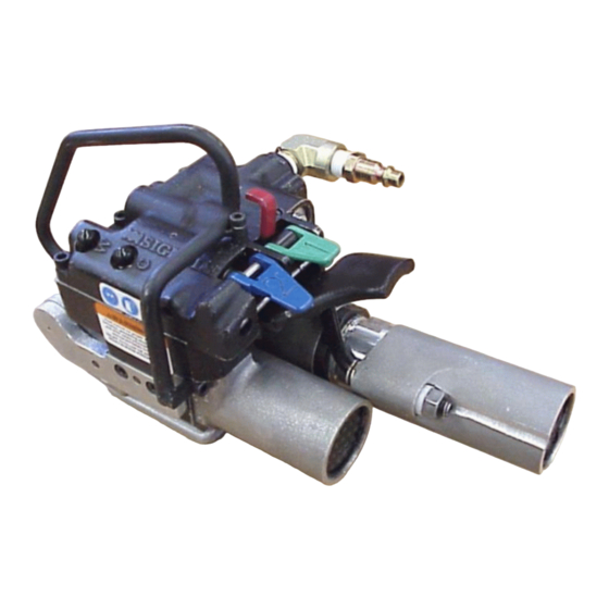
- Page 1 VT-10/13 TENSION-WELD® STRAPPING TOOLS...
-
Page 2: General Safety Instructions
Use the correct Signode products for your application. 2. TRAINING. This tool must not be used by persons not properly trained in its use. Be certain that you receive proper training from your employer. If you have any questions contact your Signode Representative. 3. EYE INJURY HAZARD. - Page 3 7. WORK AREA. Keep work areas uncluttered and well lighted. Several types of strap can be used with this tool. Use the correct Signode products for your application. If you need help contact your Signode Representative. SAFETY PROCEDURES FOR TOOL OPERATION Before using this tool, read its Operation and Safety instructions.
-
Page 4: Table Of Contents
THICKNESS 9.0mm (.354") Tenax 0.016" to 0.032" VT-10/13 & 10.5mm (.413") (0.40mm - 0.81mm) Contrax 12mm (.468") NOTE: VT-10 has an adjustable tension range of 30 to 100 lbs. VT-13 has an adjustable tension range of 80 to 200 lbs. -
Page 5: Major Components
MAJOR COMPONENTS... -
Page 6: Pneumatic Information
Filter-Regulator-Lubricator Unit, 1/2" NPT (Signode Part No. 424773) FRL Mounting Bracket (Signode Part No. 071982) Air Hose, 1/2" ID, 3/8" Fittings (Signode Part No. - Page 7 The remaining moisture is removed at the water leg in the piping system or in the filter (Part No. 008559). NOTE: Additional information is available in the Signode publication, "Air Supply Manual" (Part No. 186038). If you have any questions, contact your local Signode Representative.
- Page 8 Air pressure is assumed to be 90 psig (6.2 Bar) with recommended size and length of air hose. Volume of air is at room temperature and sea level pressure, or so-called "free air" conditions. For more detailed information about air supply systems refer to Signode manual Part No. 186038.
- Page 9 An air line dryer adjacent to the compressor. b. Use lubricant recommended by Signode. Signode has tested the use of anti-freezes, none work well in air tool; the tool will gum up when anti-freezes are introduced and will not function properly.
- Page 10 PNEUMATIC DIAGRAM...
- Page 11 BLANK...
-
Page 12: Operating Instructions
OPERATING INSTRUCTIONS Wear safety glasses. Stand to one side of the strap when tensioning. Make sure all bystanders are clear before proceeding. PLEASE NOTE: Do not operate tool without strap, as damage to the tool may occur. 1. With the dispenser placed behind you, bring the strap over the top and around the package, place the straps together and... - Page 13 3. Recheck the strap alignment at the rear of the tool and realign if necessary. Release the tension motor. Press down the Green Tension Control Lever to begin tensioning the strap. When the tension motor stalls, indicating completion of tension, release the control lever.
- Page 14 OPERATING INSTRUCTIONS, Continued 5. The internal weld timer is energized. The main piston brings the welding pads together and the strap is welded. The supply end of the strap is then cut off. Pull the cut strap away from the tool during welding.
- Page 15 STRAP JOINT INSPECTION This tool is a Tension Weld® type sealer. A properly made joint will appear as shown in the illustration. If the joint does not appear as shown, then the operator must proceed as follows: 1. Insure that the tool operating instructions are being followed before applying another strap.
-
Page 16: Adjustments
4. If you are unable to produce an acceptable joint or if you have any questions as to whether your tool is producing good weld strength, contact your Signode Sales Representative. LOCATION OF WELD TIME ADJUSTMENT 5. - Page 17 FEEDWHEEL TO GRIPPER PLUG The feedwheel to gripper plug clearance may require readjustment if the feedwheel or gripper plug has been replaced. The feedwheel clearance should also be inspected during routine tool maintenance procedures. Adjust the feedwheel clearance as follows: 1.
- Page 18 TOOL ADJUSTMENTS, Continued STRAP CUTTER The VT strap cutter has two serrated cutting edges. After the first edge has become dull or strap cut-off becomes difficult the blade can be remounted to use the second cutting edge. Once both edges have become worn the blade should be replaced.
- Page 19 BLANK...
-
Page 20: Parts List, Tool
PARTS LIST PART NO. DESCRIPTION 425460 TENSION MOTOR 8:1 (VT-13) 425470 TENSION MOTOR 3.1:1 (VT-10) 425450 WELD MOTOR 425308 COVER ASSY 425258 FRAME (MACH) 425505 SPIROID PINION 425510 SPIROID GEAR 425283 GEAR HOUSING (MACH) 425275 BASE (MACH) 425850 HANGER ASM... - Page 21 SPRING LEE # LC-038D-17 423932 SPRING LEE # LC-036G-1 424596 SPRING LEE # LC-032C-16M 274451 Ø3 X 10 DOWEL PIN 425873 O-RING SAE# 14 436380 NAMEPLATE (VT-10) 436381 NAMEPLATE (VT-13) 286383 SAFETY SIGN 423953 WARNING SIGN 166063 M5 X 20 SHCS...
- Page 22 NEVER remove the air valves when air is connected to the tool. Removing an valve with air to the tool will cause the valve to violently release from the tool.
- Page 23 * Use Loctite #242 or equivalent. ** Use Loctite #609 or equivalent. NOTES: For optimum tool performance, fill gear housing one-third full of Red Mobilith SHC 007 Grease (Signode Part No. 425239).
-
Page 24: Parts List, Air Motors
PARTS LIST, TENSION MOTOR, 425460 (VT-13) PART NO DESCRIPTION 424166 LOCKING NUT 080315 RETAINING RING 023547 BALL BEARING 425454 IDLER CARRIER 024605 IDLER 090065 LOCKING PIN 424153 MOTOR GEAR HOUSING 024608 RING GEAR 423151 WASHER 014541 BELLEVILE SPRING WASHER 425455 SPACER 023481 BALL BEARING... - Page 25 PARTS LIST, TENSION MOTOR, 425470 (VT-10) PART NO DESCRIPTION 424166 LOCKING NUT 080315 RETAINING RING 023547 BALL BEARING 425228 IDLER CARRIER 425229 IDLER 090065 LOCKING PIN 424153 MOTOR GEAR HOUSING 422870 RING GEAR 423151 WASHER 014541 BELLEVILE SPRING WASHER 425455...
- Page 26 PARTS LIST, WELD MOTOR, 425450 PART NO DESCRIPTION 080315 RETAINING RING 424181 FLAT WASHER 014541 BELLEVILLE SPRING WASHER 090118 BALL BEARING (SEAL) 425458 FRONT END PLATE 024602 SPACER 024612 FRONT END PLATE 425453 ROTOR 090052 CYLINDER 424164 SPRING PIN 424154 BACK END PLATE 424161 BALL BEARING (SEAL)
-
Page 28: Troubleshooting
TROUBLESHOOTING The following items are the most common types of tool malfunctions. For symptoms or remedies not shown, contact your Signode service representative for additional information and details. The following tool conditions are shown in this manual: AIR SUPPLY #1 - The air motor is frozen. - Page 29 CAUSE REMEDY Feedwheel is clogged with dirt or strap residue. Clean teeth on feedwheel with the cleaning brush (Signode Part No. 023963) provided. Worn teeth on the feedwheel. Replace the feedwheel. Excessive or improperly set feedwheel to gripper Adjust feedwheel gap as required.
- Page 30 TROUBLESHOOTING, Continued #7 CONDITION: A poor weld identified by an incomplete area of weld. CAUSE REMEDY Welding is achieved by a combination of vibration and Dismantle and clean the weld mechanism by brushing downward pressure of the upper gripper. Either a away the strap residue or washing the entire unit in a restriction of motion or a reduction of downward solvent.
- Page 31 #11 CONDITION: Strap weld time is erratic. CAUSE REMEDY Air leakage in timing circuit. Check o-rings and pneumatic components for leaks. Replace parts as required. Dirty or very dry pilot valve (Key 106). Remove, clean and lubricate the pilot valve using air line oil or replace if needed.
-
Page 32: Strap Size Conversion
STRAP SIZE CONVERSION Use th following instructions to convert a tool’s strap size. Use the illustrations below for reference when changing strap size: 3/8" (9.0mm) STRAP 1716 (10.5mm) STRAP 1/2" (12.0mm) STRAP FIGURE-A FIGURE-A FIGURE-A FIGURE-B FIGURE-B FIGURE-B 1. Use the reference guide (Figure “C”) to determine the proper FIGURE-C strap size. -
Page 33: Options
VT can be suspended in various operating positions by using the proper tool hanger and hardware. Review the illustrations below for the appropriate configuration for the tool application. Applications are recommended to use an Overhead Tool Balancer as shown (Signode Part No. 423283). HORIZONTAL SEALING... -
Page 34: Maintenance
TOOL MAINTENANCE 1. Clean the teeth on the feedwheel and the gripper plug with the special brush provided. 2. Periodically clean the tool with compressed air. 3. Disassemble, clean and lubricate the welding mechanism. GEAR HOUSING Periodically check the gear housing portion of the tool: 1. - Page 36 Signode reserves the right to replace any tool which proves not to operate per functional specifications with a new or like-new tool of the same model if in Signode's judgement such replacement is appropriate. Any new replacement tool provided to an owner will carry a full sixty (60) day warranty. Any warranty repaired tool or like-new replacement tool will carry a warranty for the balance of the time remaining on the initial sixty (60) day warranty.
Need help?
Do you have a question about the VT-10 and is the answer not in the manual?
Questions and answers